
A combination 3D printing and engraving project
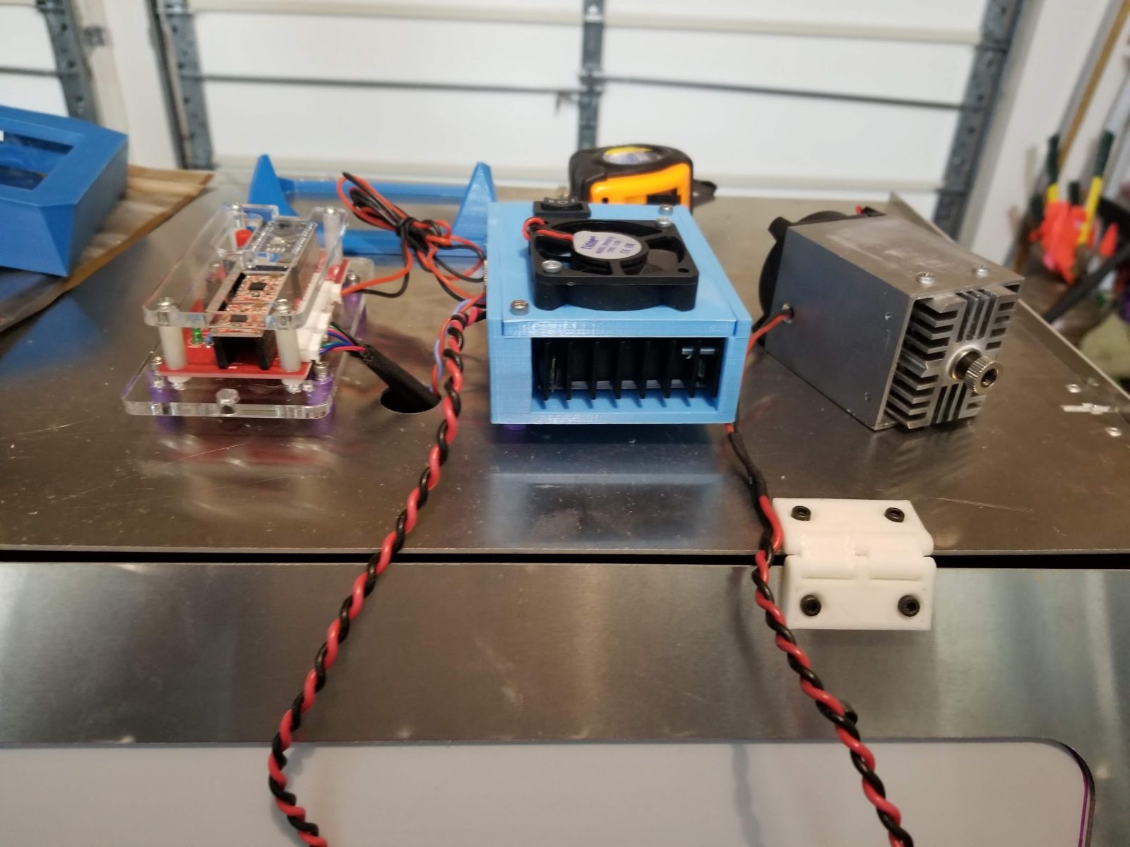
A modified Eleksmaker A3 Pro Frame with a 10-watt Endurance Laser.
Introduction to Eleksmaker (a universal laser engraver / Foxalien machine) and Endurance lasers
One of my friends wanted a simple low cost laser engraver and settled on an Eleksmaker from AliExpress and had me build it for him. I assembled, tested and then took my friend through its operation. A few months later my friend bought a Glowforge and told me that he didn’t want the Eleksmaker anymore so he gave it to me. When I got it, it had several of the acrylic pieces broken or cracked. I confirmed that I could fire the laser and run the motors with BenBox and then got to looking at how to replace the acrylic parts.
In this article I detail the process by which I rebuilt the engraver and recycled the chassis to accept a laser toolhead from Endurance Lasers. I had purchased an 10W unit to mount on my ShapeOKO but with the Eleksmaker I was inspired to switch gears and mount it there instead. I wanted to get the laser working on this chassis using commonly available firmware and control software without buying anything additional. At most I expected to recycle some existing hardware (nuts, bolts, washers) and an M5 threaded rod, but in the end the project turned into a number of smaller sub-projects to achieve the goal.
Initial Assessment
The first issue was of course to replace all the acrylic pieces, and not just the broken parts. I didn’t want anything to be mismatched in terms of materials and suspected that the intact acrylic parts may not survive anyway. I also found the BenBox software to be really cumbersome and felt that it would be better to use something like LightBurn or T2Laser.
Looking around Thingiverse, I found this set of identical parts along with an adjustable Z-axis that would be a perfect drop-in replacement.
Assemble the frame
Since all the fasteners were still in place, I decided to replace each part in turn instead of a full teardown and rebuild. This made sure that the chassis remained square throughout the build and I didn’t have to worry about resetting tension on any belts.
I assembled the frame in 3 phases:
- The main chassis parts composed of the corner pieces
- The Y-axis motion system and X-axis gantry
- Laser mount
I left the laser mount for last because that was what was going to need any serious modifications. The Eleksmaker laser tool head does not line up exactly and I had to take some measurements and drill some holes (another reason to print at 100% infill) to match the mount points of the Endurance toolhead. I also needed to route the wiring a little differently from the Eleksmaker which just has you leave the wiring mostly dangling. I resolved that with a 3D-printed cable chain.
Finally I mounted the control box to the back of the chassis by drilling a pair of holes in the enclosure provided by Endurance and putting two M3 screws through to fasten to the chassis extrusion.
The final assembly step was to re-tension the belts before proceeding to motion tests.
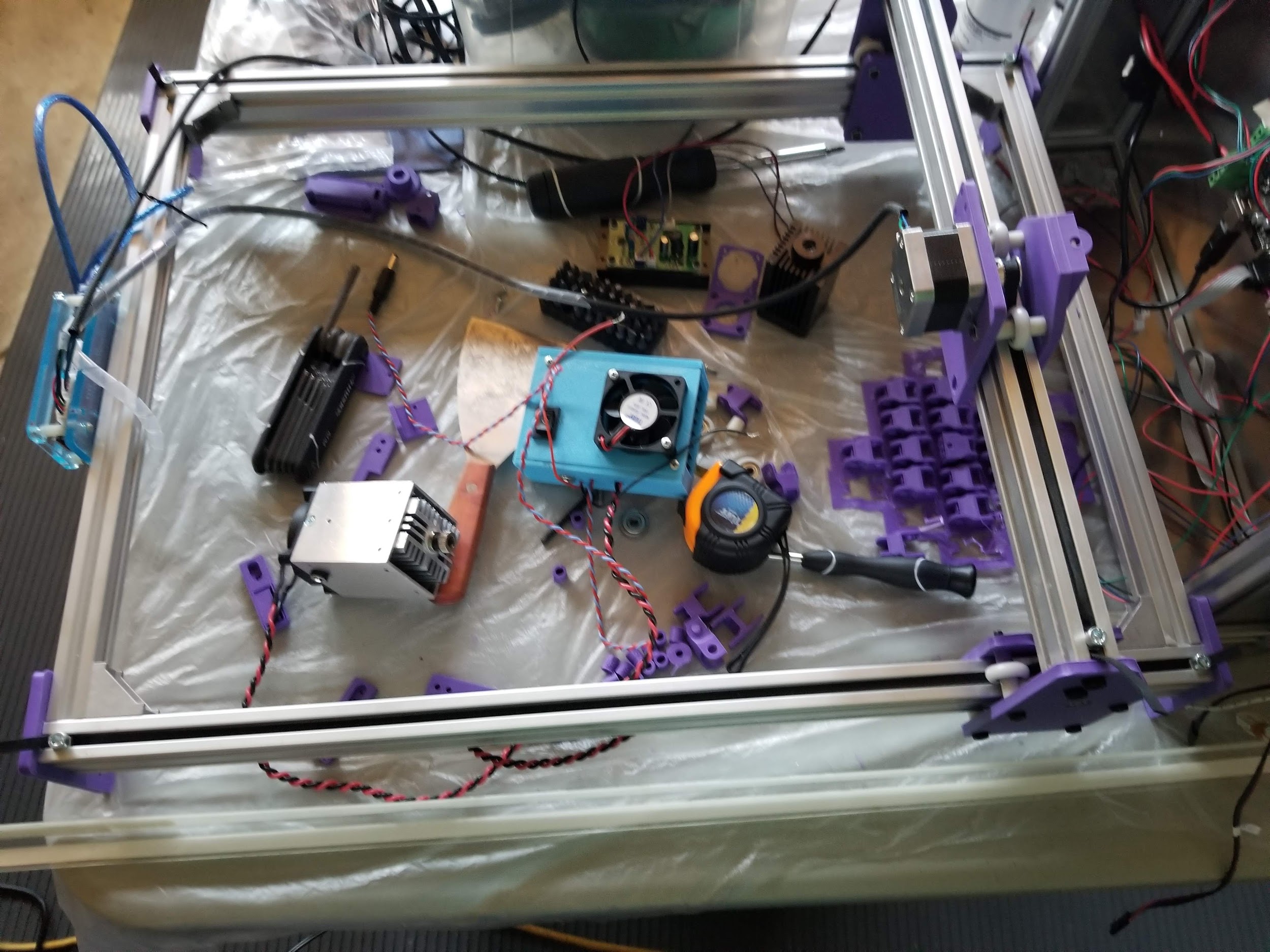
The Eleksmaker mostly assembled and ready to mount the tool head
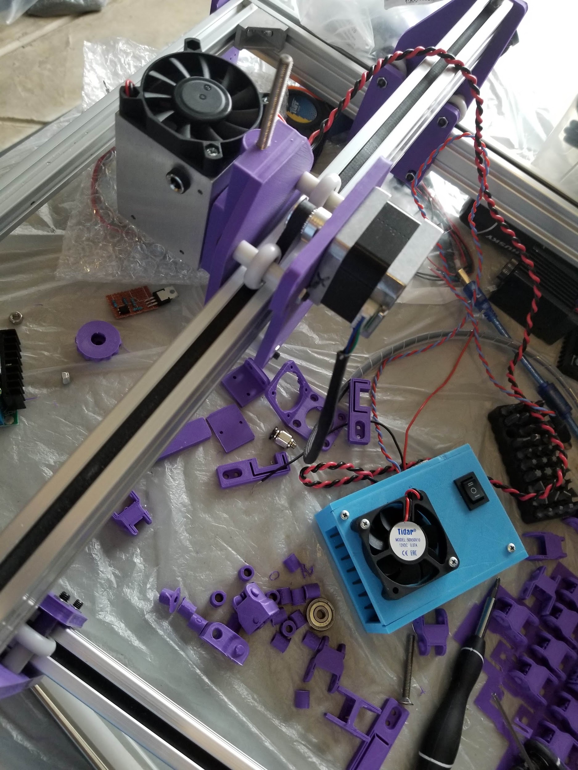
The laser toolhead mounted to the gantry
Testing
The first step was to attempt motion. With Benbox this was not a problem. I was able to connect just fine and move the axes, but was never able to fire the laser. I was likewise unable to do much with LightBurn The Eleksmaker had an older version of Benbox’s firmware on board the Mana board it came with. While I was able to follow Endurance’s instructions for switching firmware, in the end, I simply downloaded T2Laser’s trial software and used it to load GRBL 1.1f on board. Once I loaded it, I was able to operate the motion system and fire the laser just fine.
After that, it was time to do some engraving and cutting. After focusing the laser, I started cutting panels for a flight simulator I was building and then moved on to other projects. All in all I was very happy with the outcome. I had turned a cheap Chinese laser rig into a powerful machine with a 24”x24” work area with just a little effort and plenty of help from George and his team at Endurance.
- Attempt movement using BenBox
- Test existing laser toolhead (500mW)
Meltdown
One of the reasons I wanted a laser cutter was to cut bulkheads and panel parts for my RC airplane builds. I was particularly interested in cutting foamboard — the sort you can buy at your local hobby or craft store for very little. The laser was going to give me a leg up on getting some neat airplanes in the air.
I began cutting some test panels and noticed that I needed to play with the power and speed to address the material because while I could cut through the top layer of paper, the laser would either melt the foam or not penetrate past that top layer. Once I got reasonably successful settings in place, I went about getting a few panels. For just 2 minutes, I turned my back to cut a second piece of waste-board for the laser…..
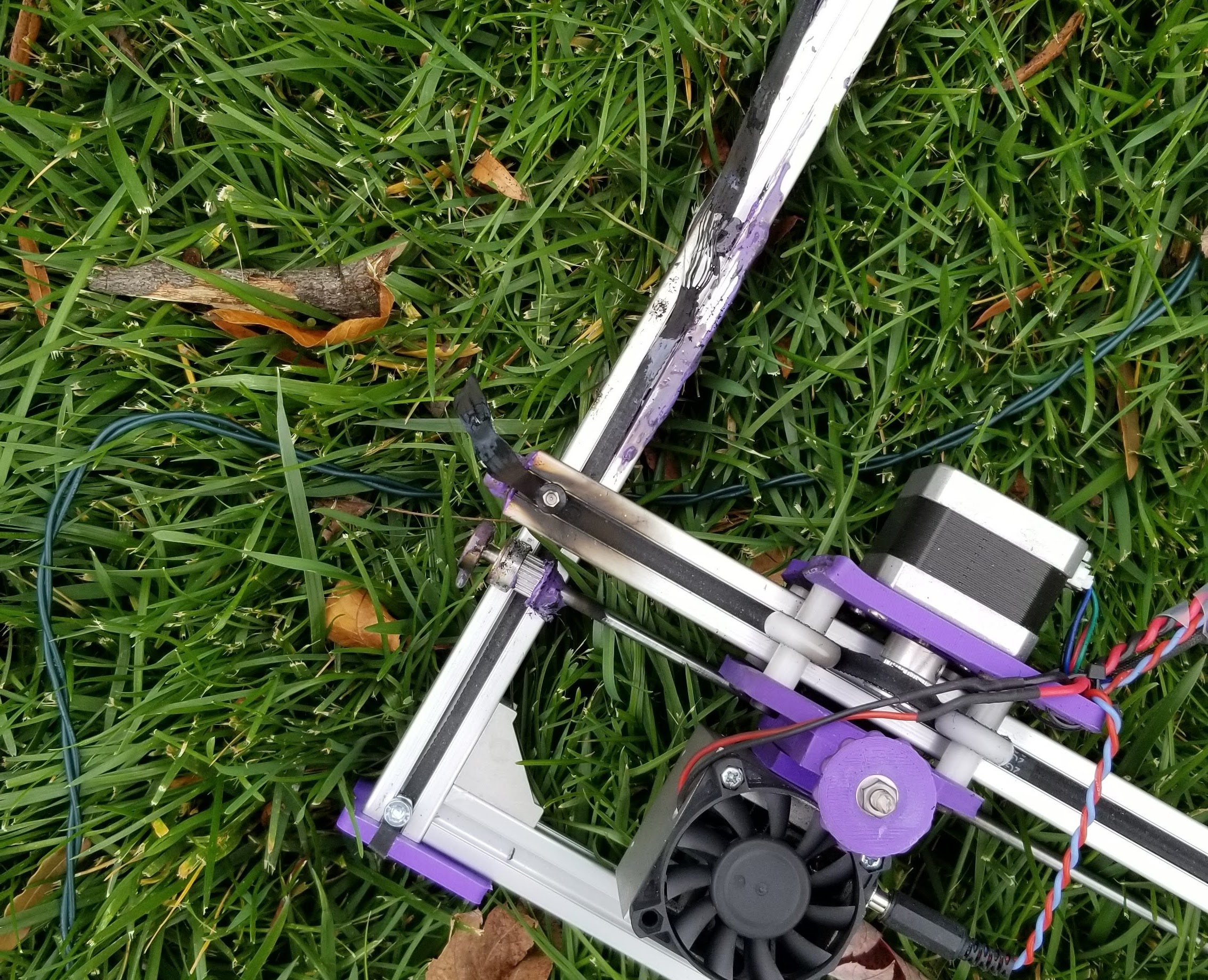
The Eleksmaker after the mechanism jammed on a piece of Depron foamboard and melted the plastic parts
Needless to say, I needed to rebuild the machine again. Fortunately, I was able to recover most of the chassis, but I lost one of the Y- axis extrusions, one side of the X gantry including all the associated wheels and bearings. Happily, the side of the X gantry that melted was not the one with the stepper motor for Y-axis traversal. The laser was intact and everything was fine.
Rebuild
I decided to repurpose an enclosure I had built from some plans online for one of my 3D printers, but the original Eleksmaker chassis is too long in one axis to fit. Worse, I did not want to cut the metal axle/bar that runs across the X gantry to keep the two sides of the gantry in line. The answer was to trim the Y-axis extrusions. This worked fine for me since I had to replace one of those anyway. I cut both to fit and then test fit the main chassis inside the enclosure.
A view of the enclosure while trying to decide what goes where. The hinges and knob are 3D printed.
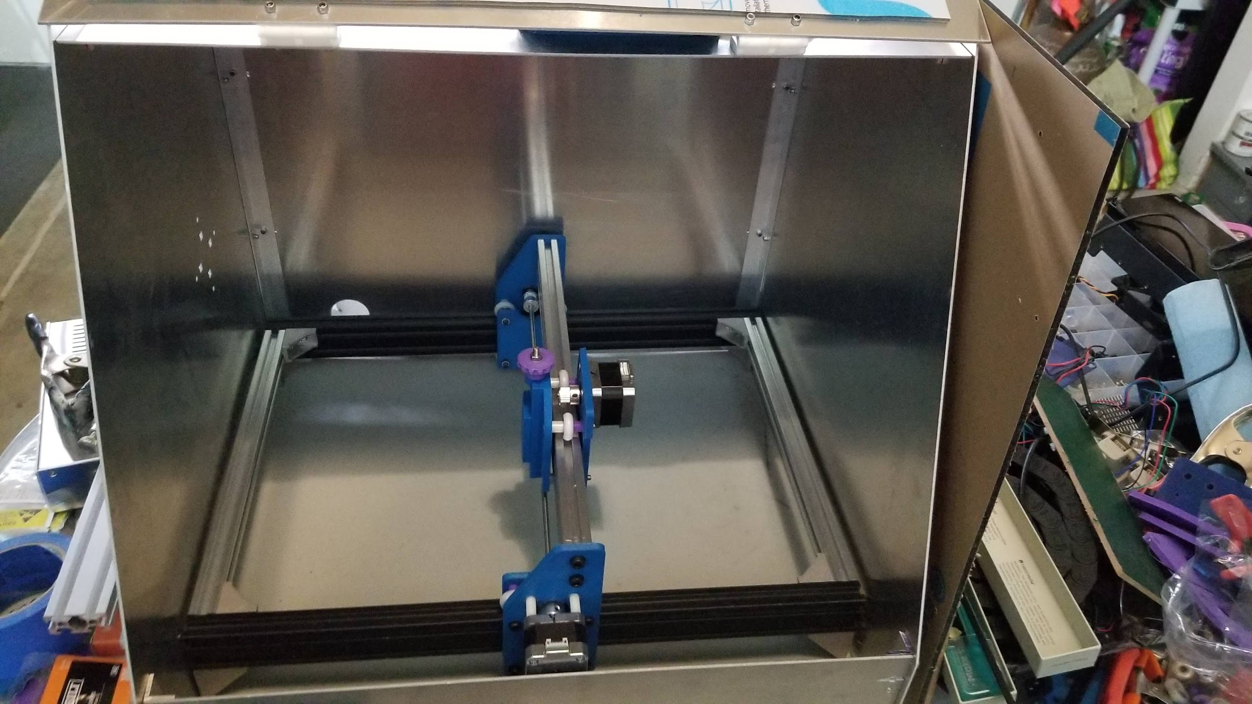
Test fitting the unwired chassis into the enclosure, rotating to fit
The enclosure has a door that raises upwards with a window opening meant for a piece of clear acrylic. I changed that to use a piece of polycarbonate to keep all the dangerous stuff inside. The one thing this enclosure lacks is a fan to vent smoke and other gases outside. That has to come separately, as at some future date I will cut a suitable hole in the back and mount a suitable fan and impeller. For now, there are enough gaps to allow all fumes to escape. However, once I install the fan, I will seal off the gaps.
As can be seen from the images above, all the parts were replaced, with 2 exceptions: a few spacers for the wheels and the Z height adjustment knob. The nice part of all this is that I can remove this particular assembly sometime in the future and bolt on a Z-axis and motor assembly to turn my unit into a 2-in-1 system with little fuss, although I suspect the belt-driven system might need a revisit due to the weight of the toolhead with a spindle.
After I was happy with the arrangement, I recycled a pair of L-shaped brackets from an older 3D printer build to hold the entire system inside the enclosure.
One issue with this arrangement is that there is little room for a cable chain. That matters a lot less here because I decided to mount all the electronics on the outside of the enclosure and run all the wiring from the “roof”. This kept all the wiring completely out of the way, eliminated much wire fatigue and made servicing that much easier. It would be straightforward to replace the controller, for example, without really touching anything inside the enclosure. I also have enough space to seat a laptop or external LCD/Touchscreen. On the back of the enclosure I have enough real estate to mount a power strip and cable clamps to keep everything nice and neat.
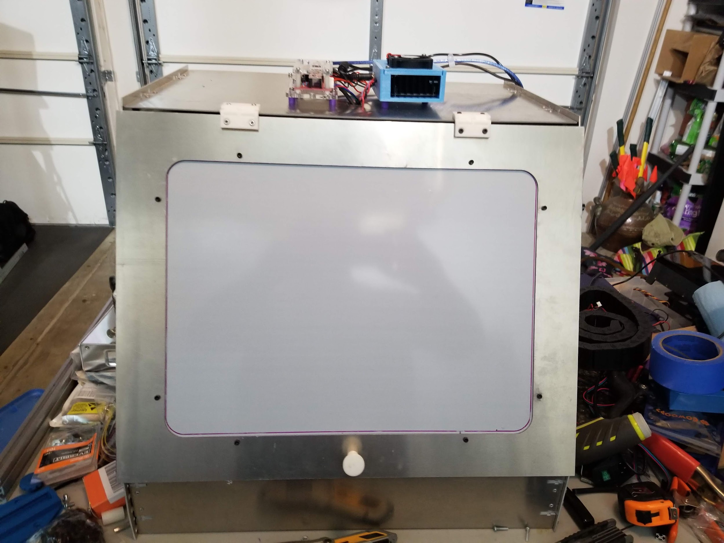
Mounting the electronics for the laser on the enclosure top or roof
As an initial step, I built a low-end PC made up of an LCD harvested from a dead laptop, an Intel ComputeStick PC and a Bluetooth keyboard and mouse as the initial controller computer, but ultimately switched to a laptop on the grounds that I will eventually install a MakersBase DLC V2.0 and TFT screen to make the rig entirely standalone (since it will accept GCode on an SD card).
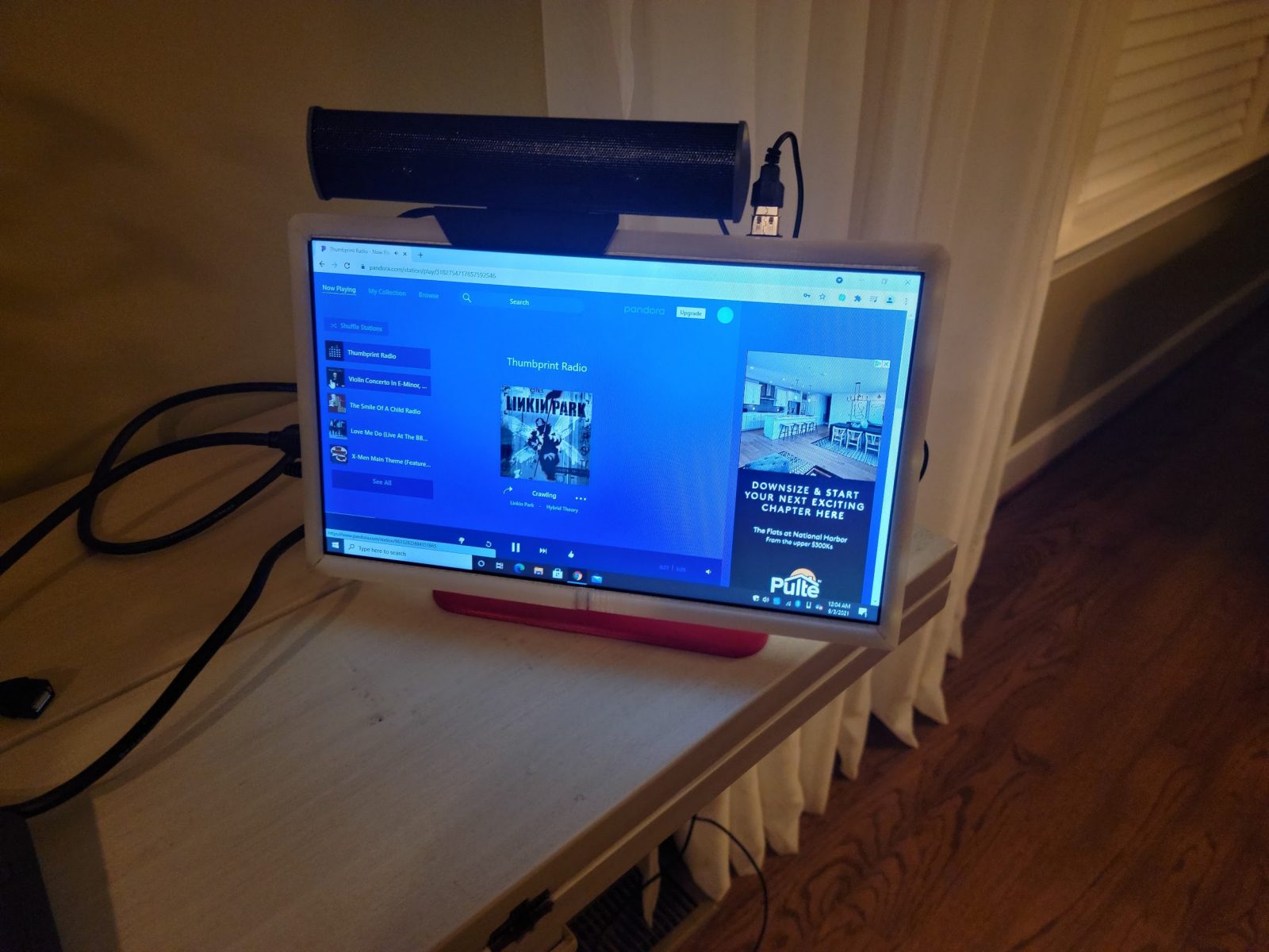
The DIY PC is being tested. The speaker would be removed when connected to the the laser as it is using up the only available USB port on the stick PC.
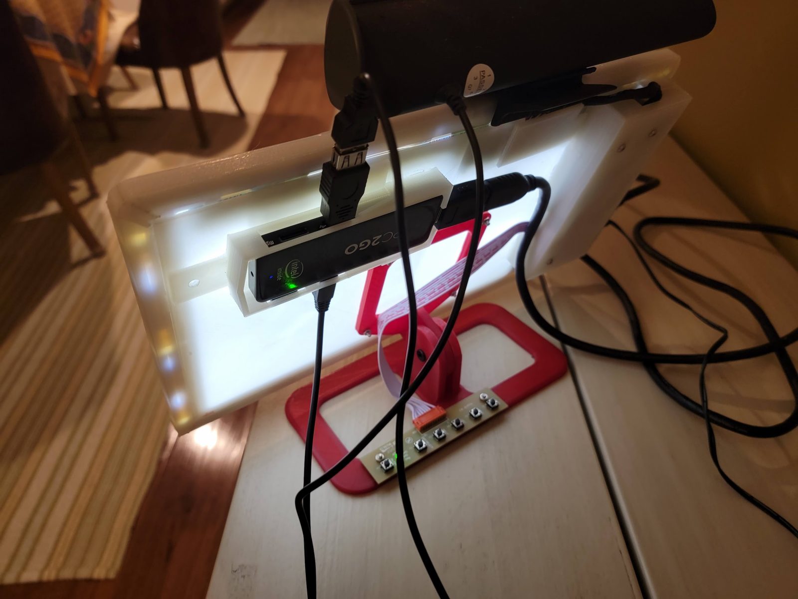
The back of the DIY PC with the ComputeStick mounted. Just needs some cable management
As a final step, I conducted a motion and firing test to complete the mechanical part of the project. With this test, I was able to do some initial cuts and run the laser as intended. Because it has no end stops I really have to be careful to fully frame my workpiece every time or set an origin. But that upgrade is for later when I add a more sophisticated board.
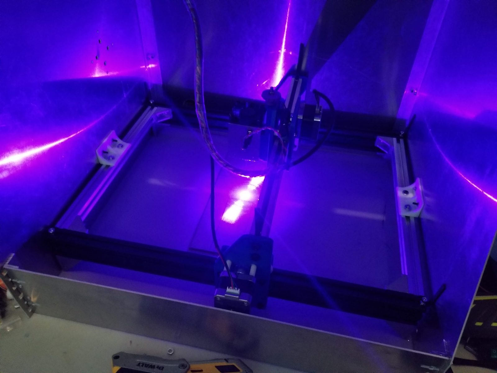
Motion and laser-firing test
written by Samer Najia
A real customer review about installing an Endurance 10 watt (10000 mw) laser on Eleksmaker frame – all you need to know
https://www.youtube.com/watch?v=XLbJJL_nR9c
If you have any questions – let us know in a Livechat.
https://3dprint.com/284190/the-top-10-things-you-can-do-with-a-diode-laser/