")
We are trying to reduce laser beam spot with a different lens.
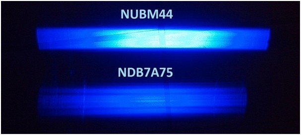
Standard 3 element lens
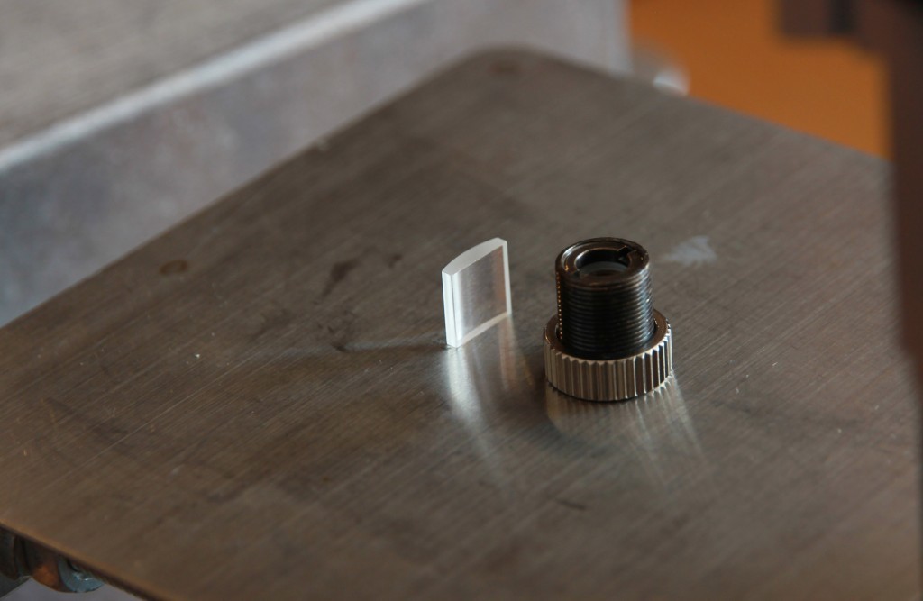
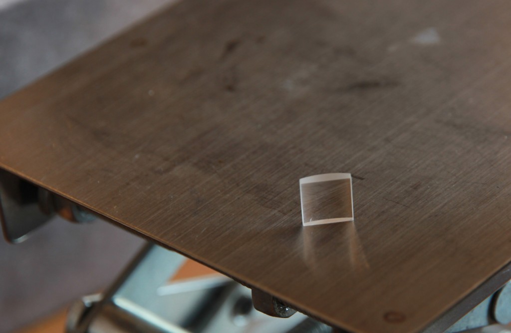
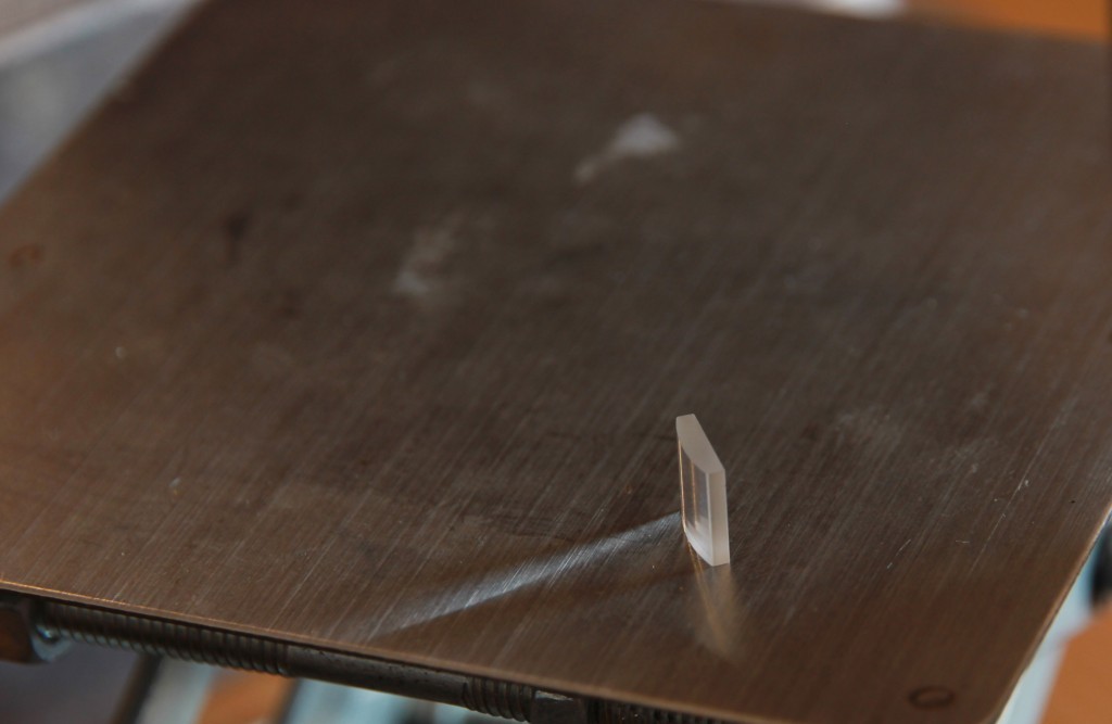
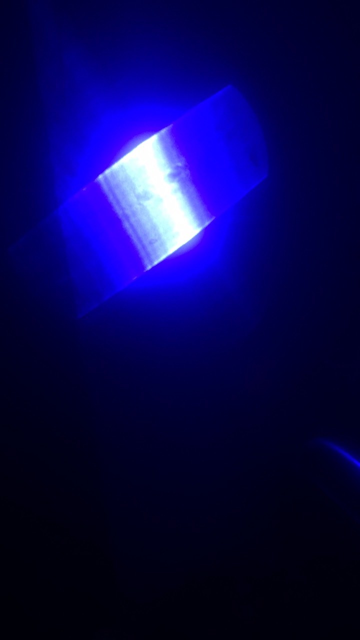
Adding additional semicilindrical lens

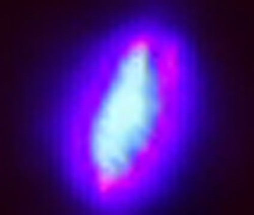
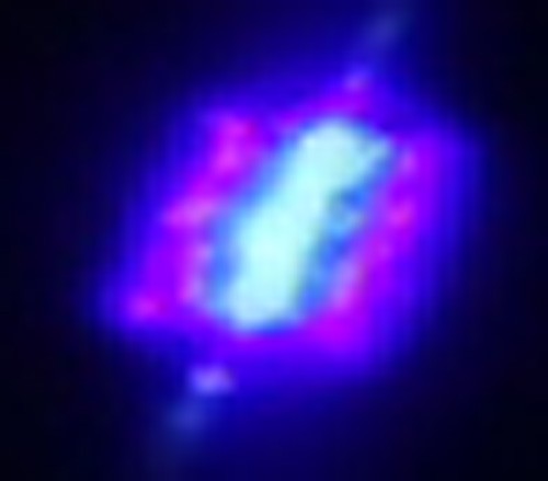
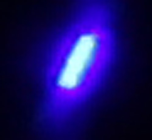
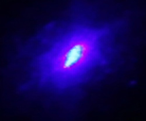
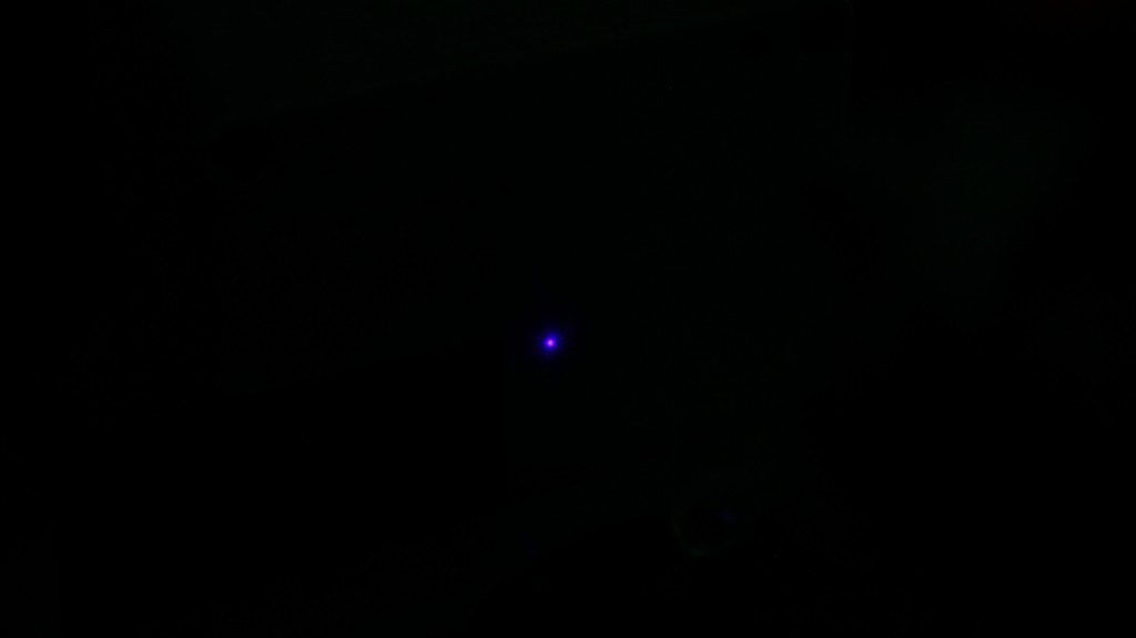
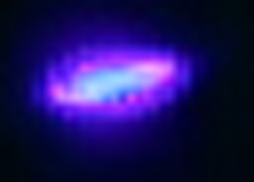
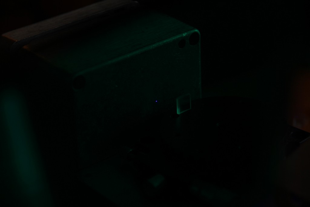
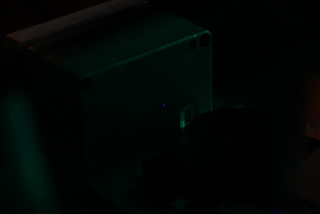
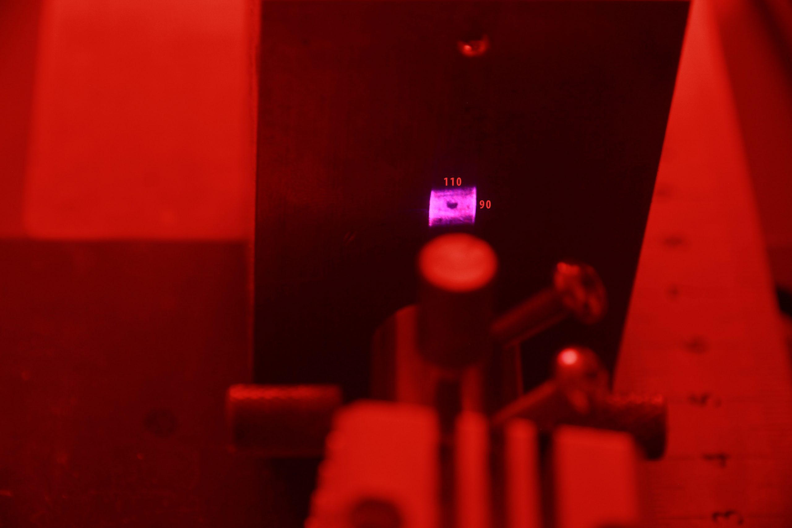
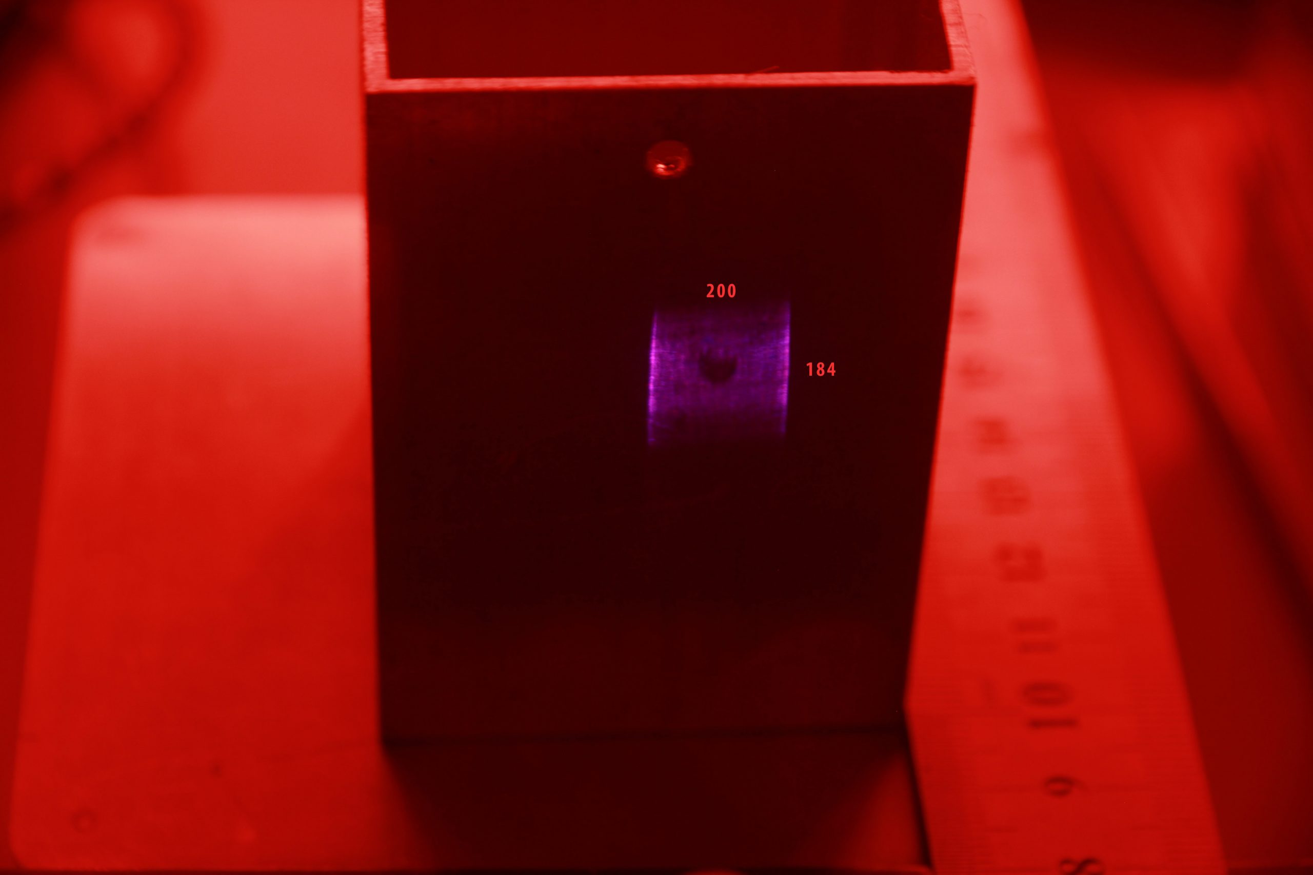
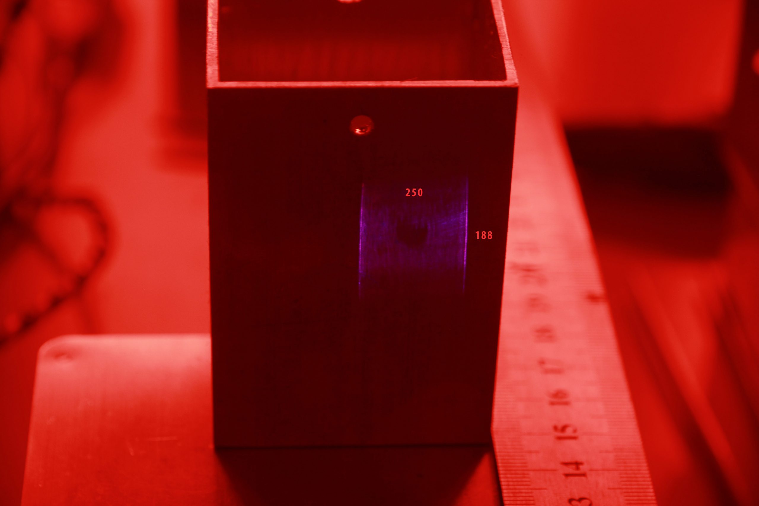
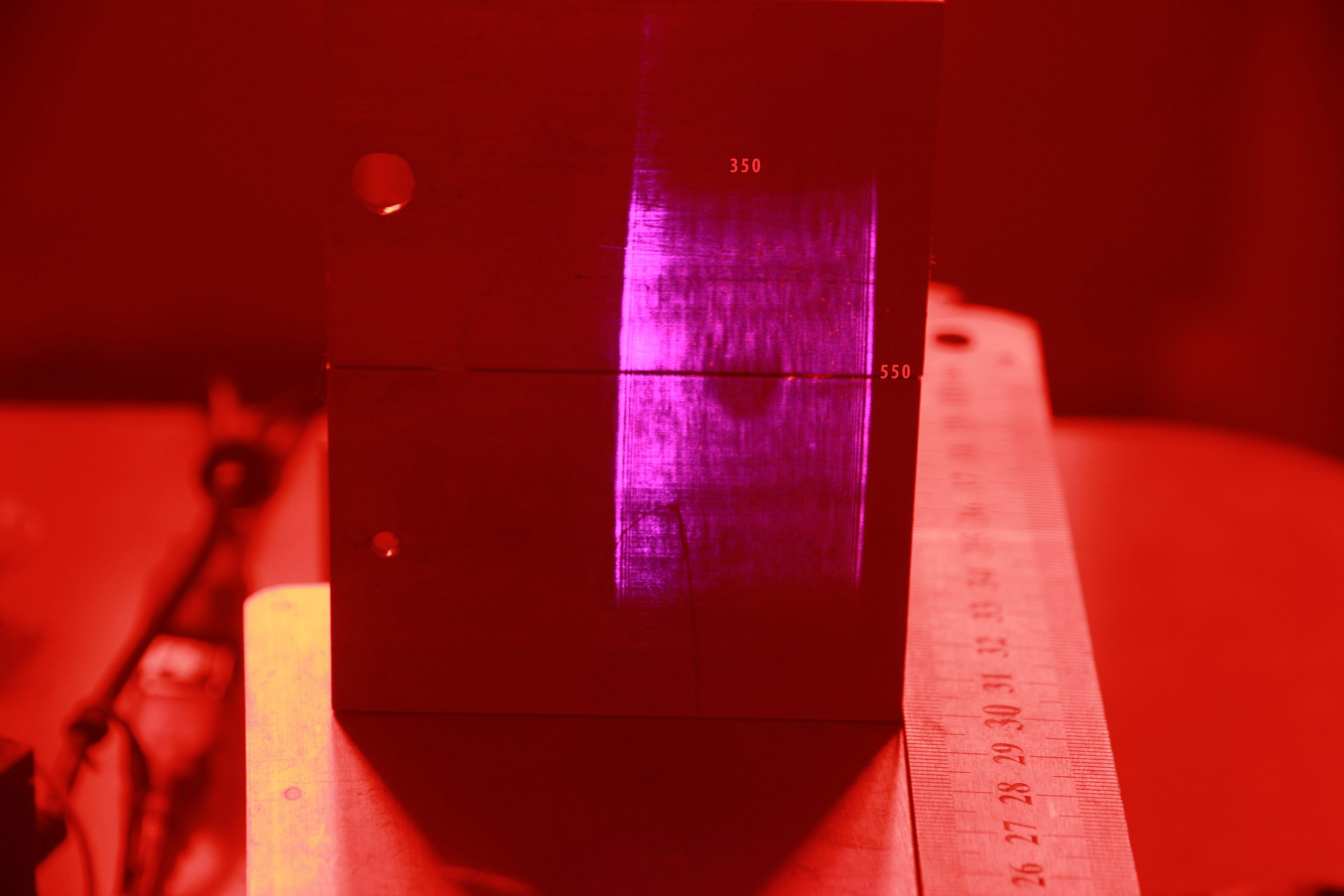
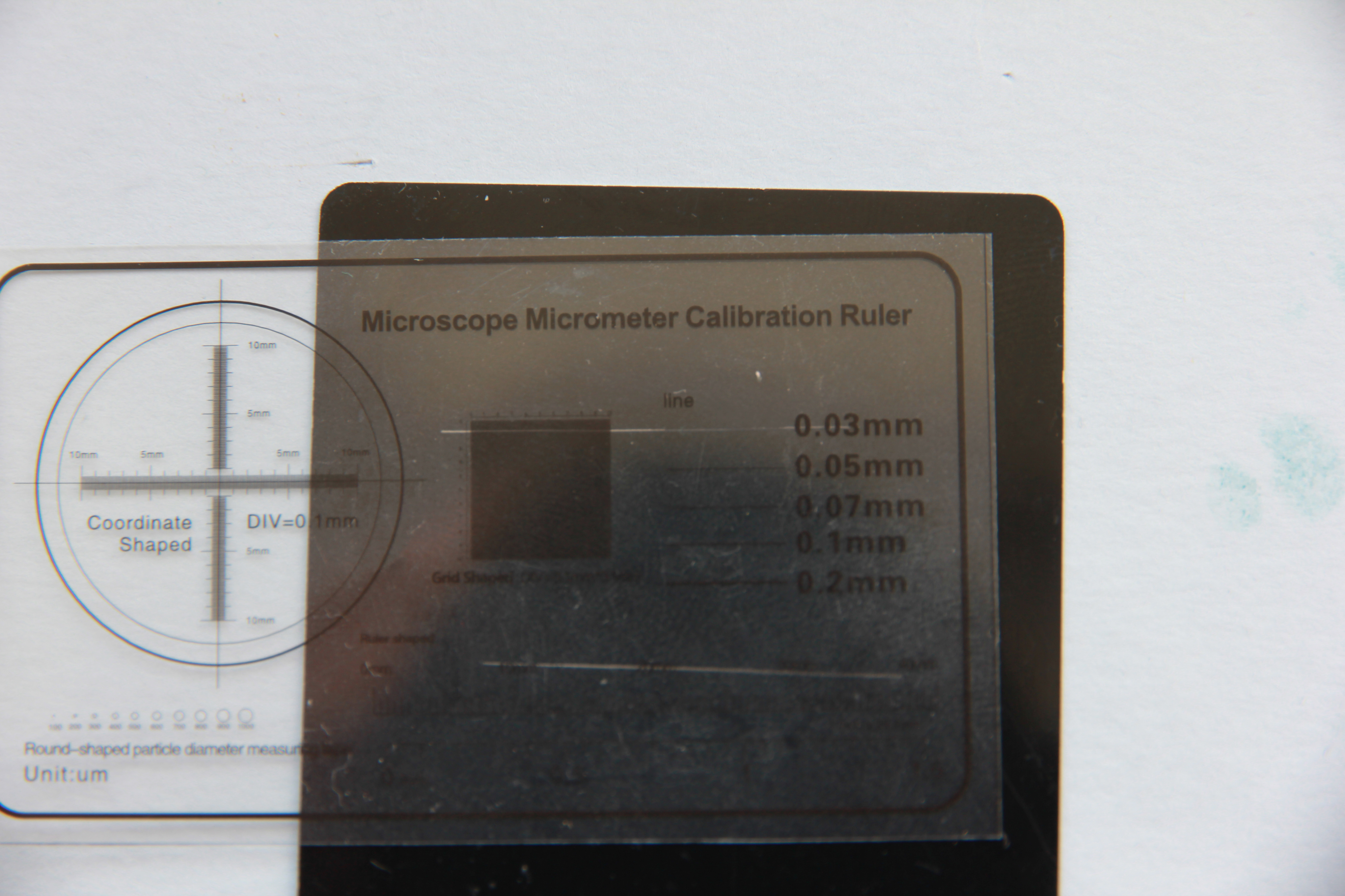
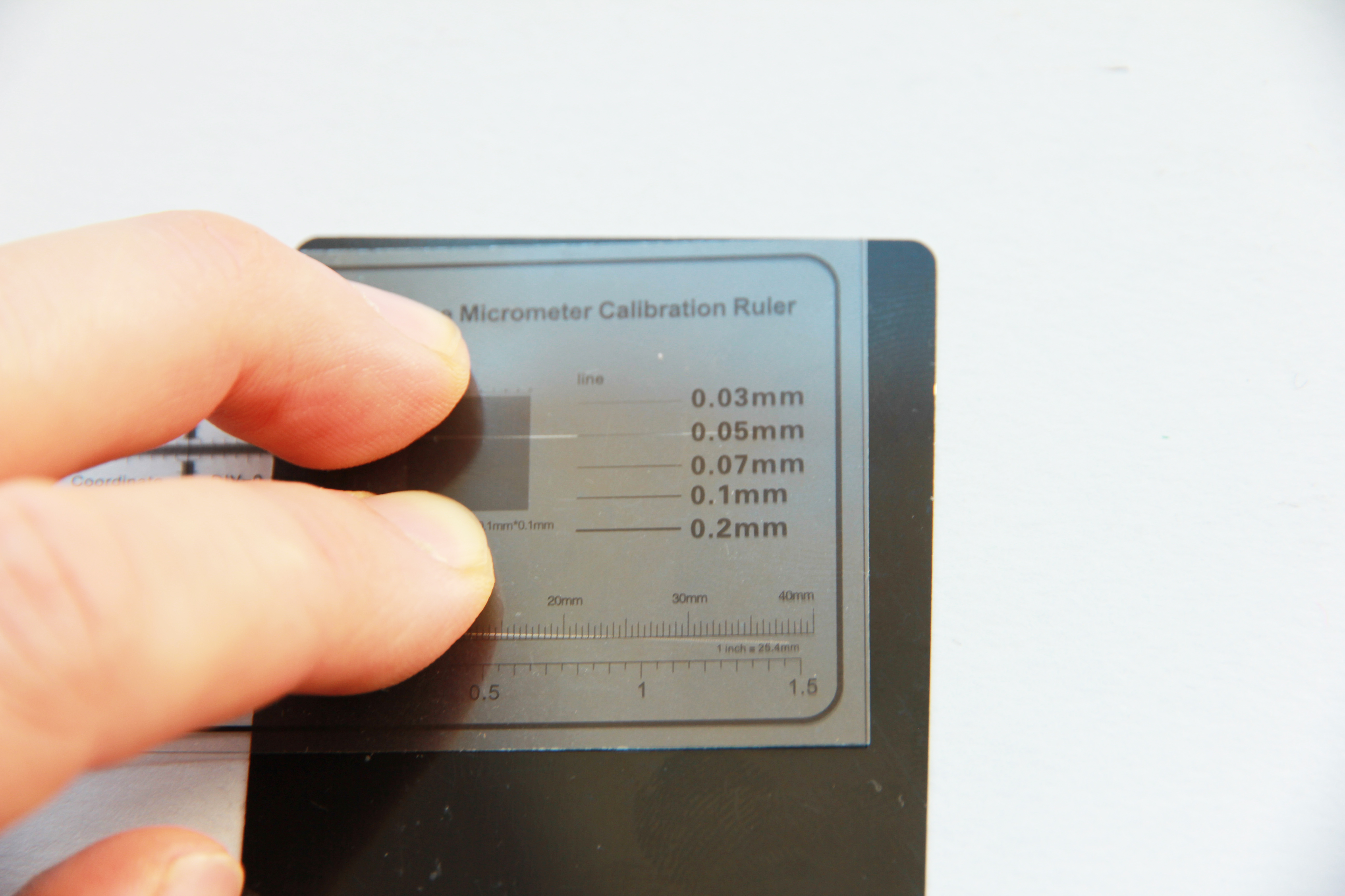
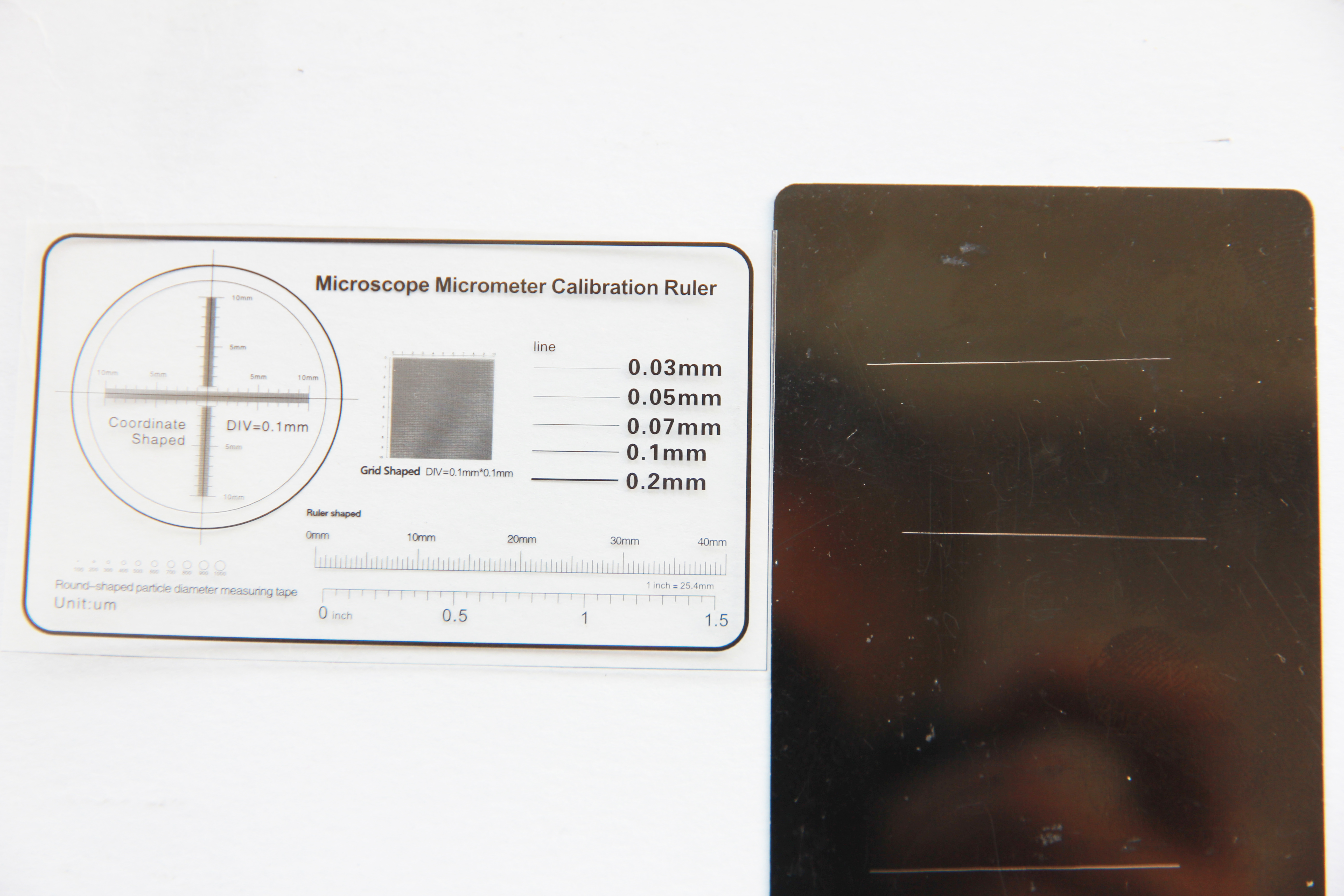
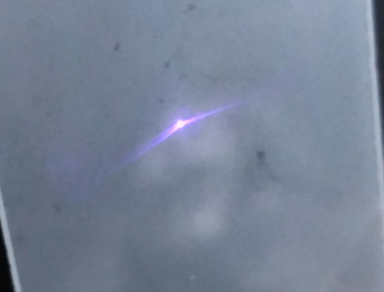
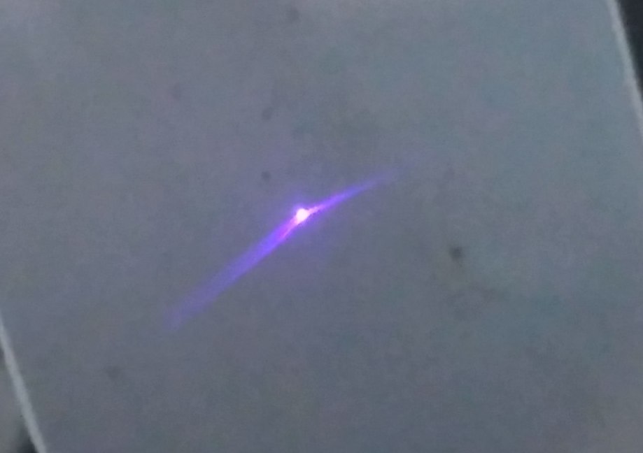
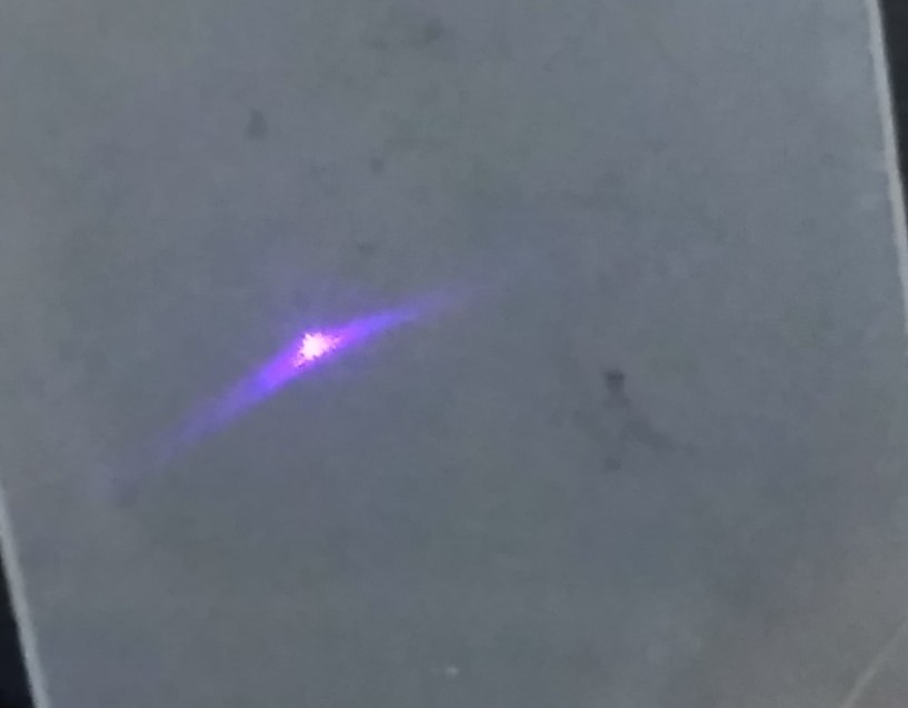
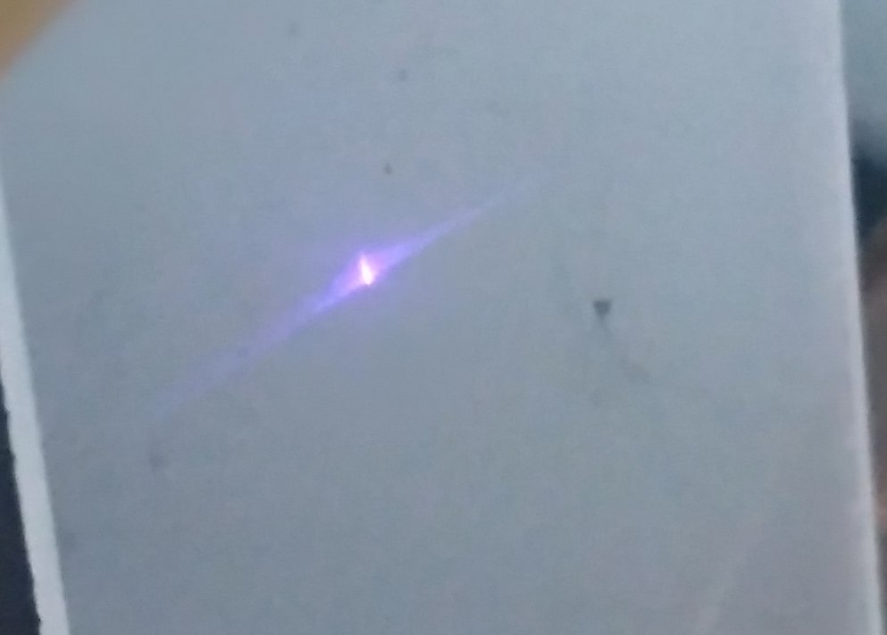
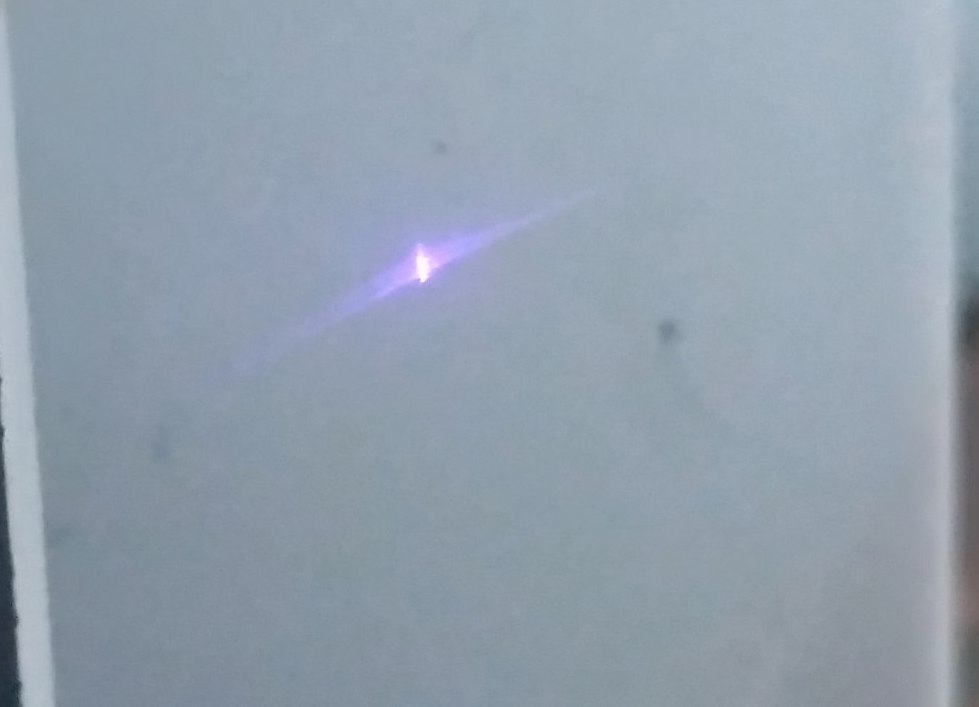
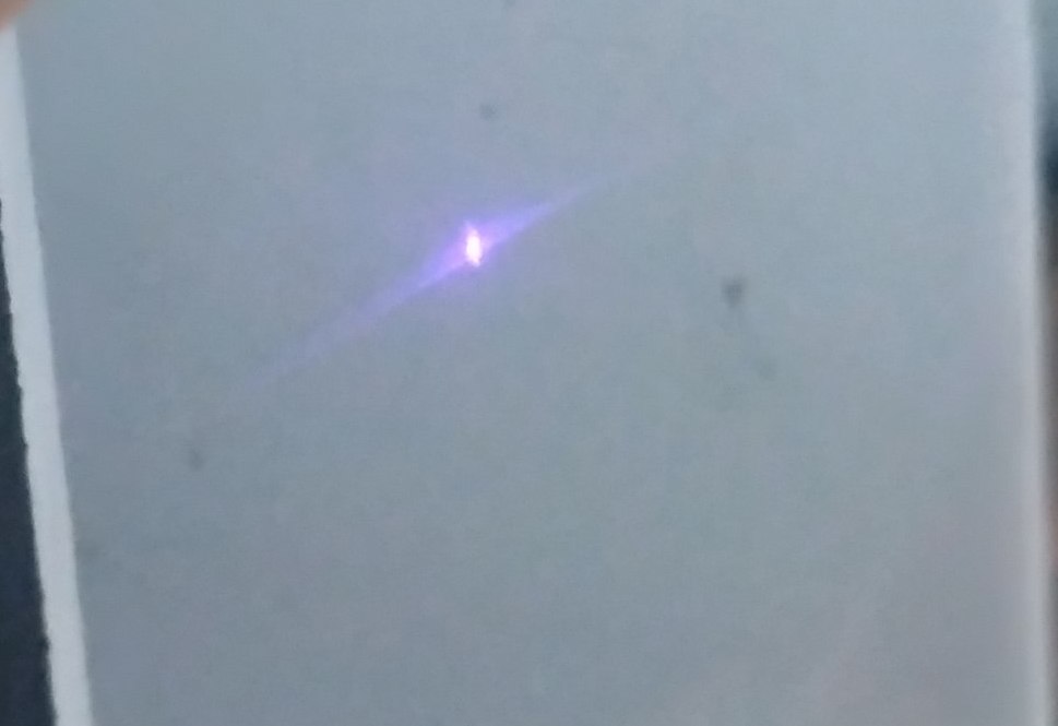
Original images where you can measure the actual size

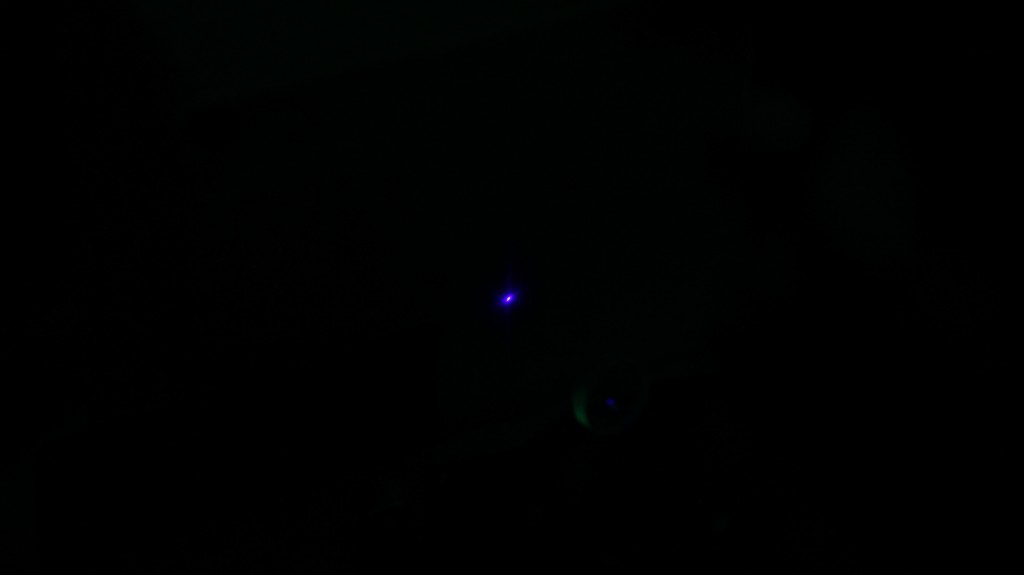
The problem that existing 3 elements, G2, G7 lens only decrease laser spot in one axis but do not decrease in the other. The is why you always see a rectangle and can not make it smaller to round or square.
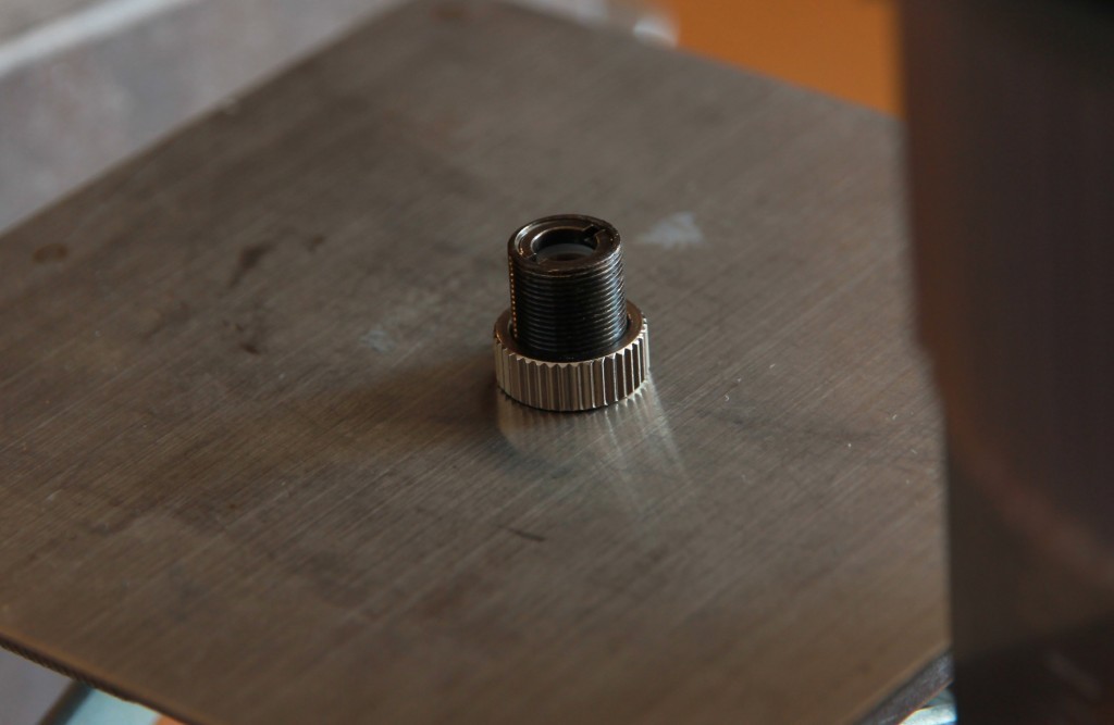
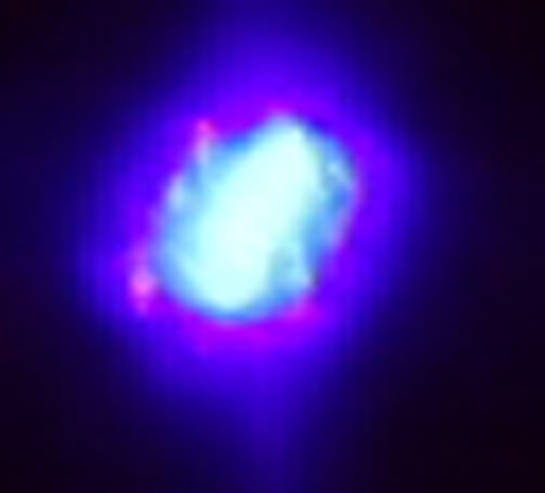
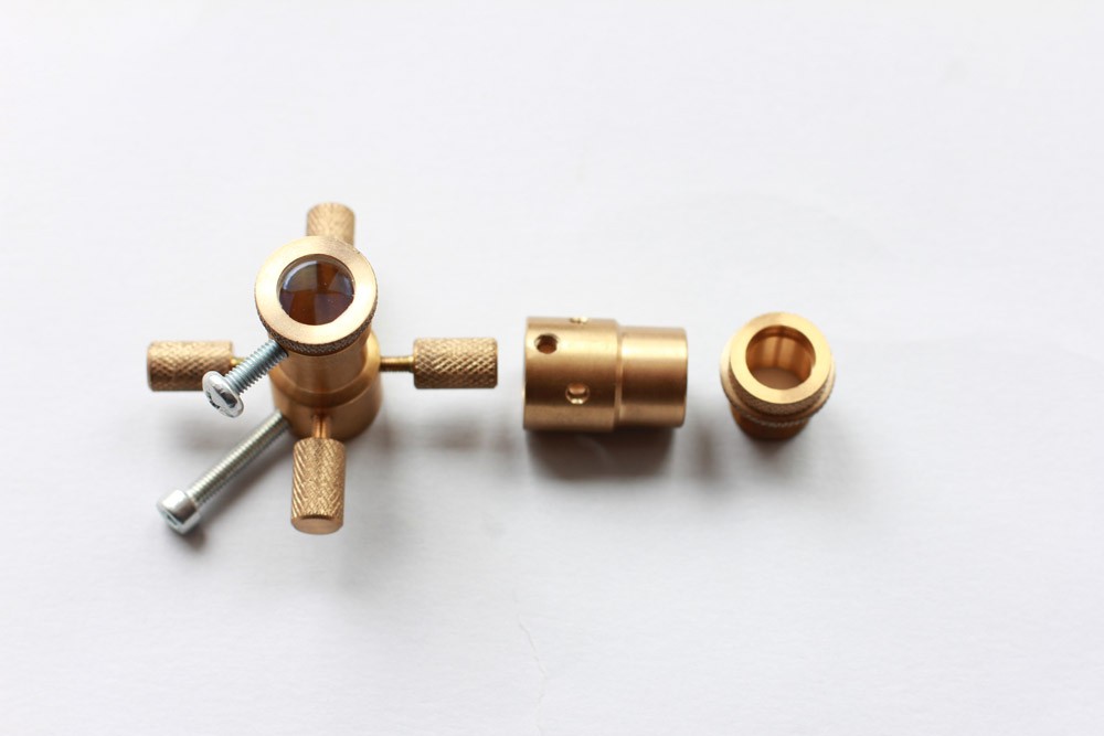
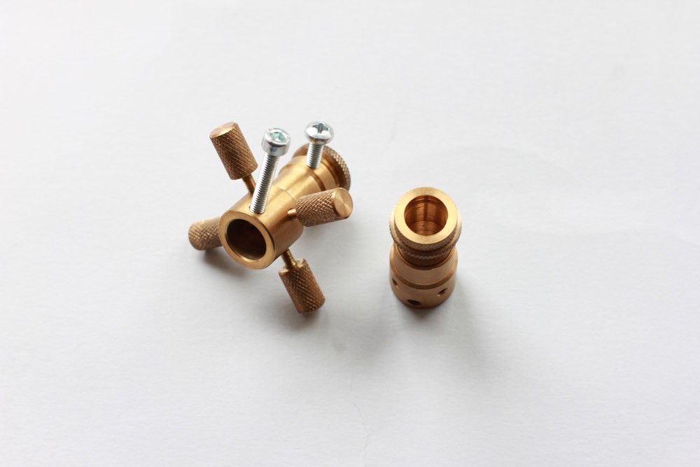
We add a new flat convex lens.
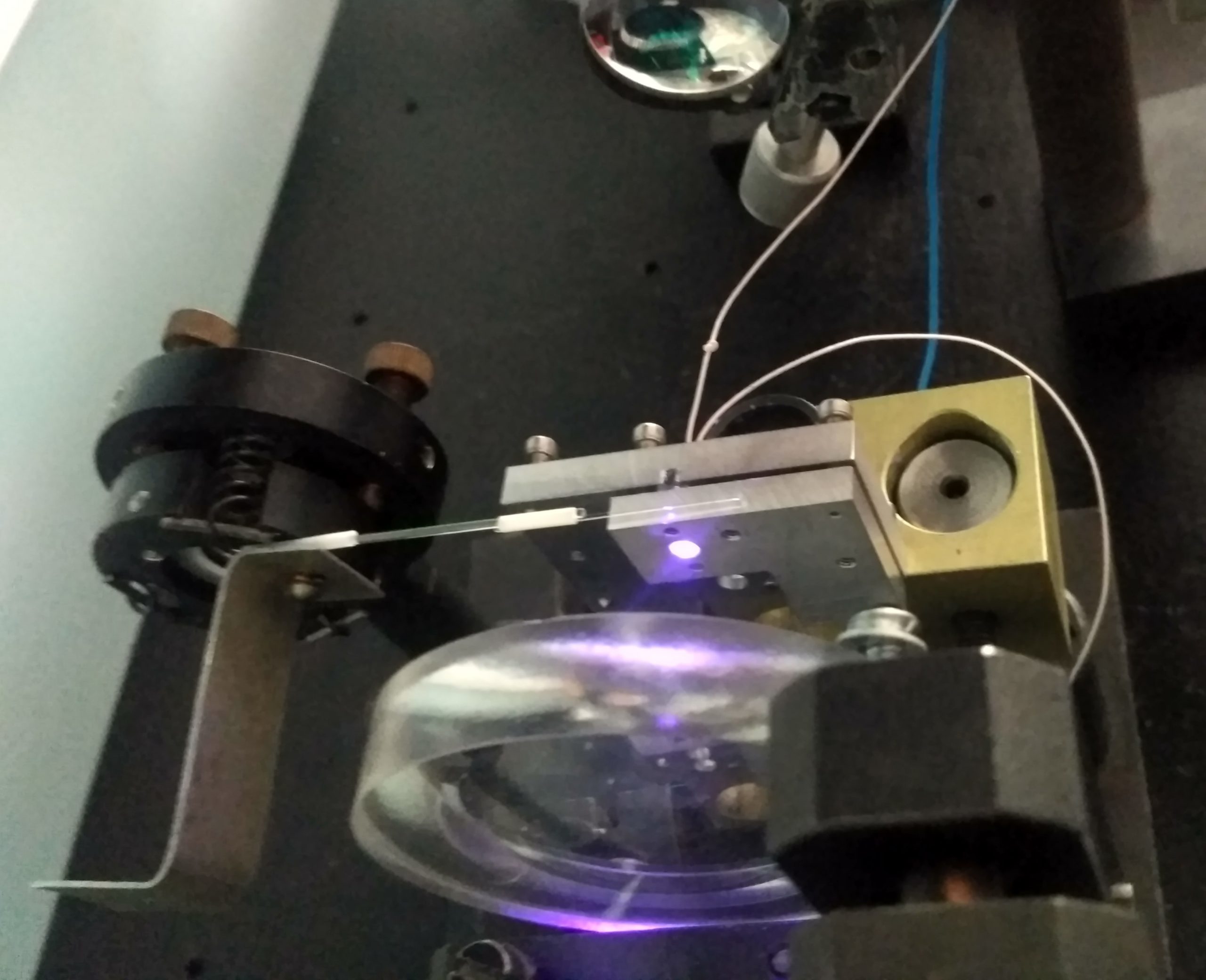
Further experiment
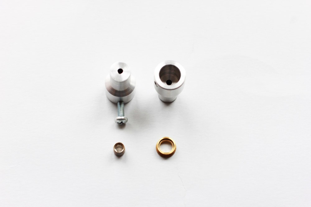
We setup a flat convex lens on 80 mm range from the laser diode. Closer to the surface.
we added Laser Beam Corrective Cylindrical Mirro set/For High Power 450nm laser Diode
For 405nm-450nm-465nm-473nm High Power Laser Diode’s Beam Collimation and correction.
With AR Coating.
Size: 8mm(L)x7mm(W)x2.5mm(thickness)
Width reduction:~2 times
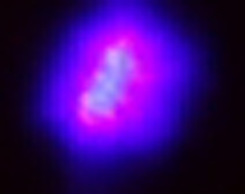
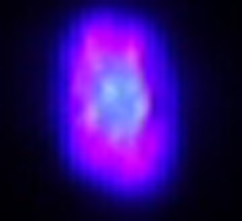
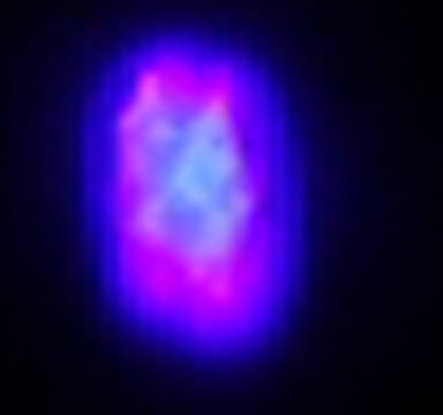
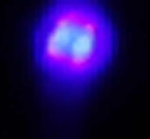
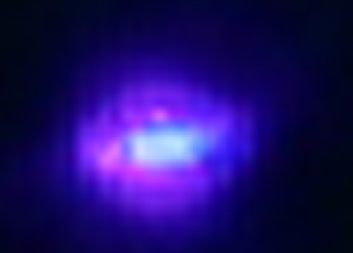
45×77 microns (uM) final beam spot vs. initial 85×130 microns (uM)
this means that the density of the laser spot will be 400*600 / 200*350 = 3.4 times more, therefore, Endurance lasers can be ~3-3.4 times more efficient compared to standard 3 element
New laser lens developing scetch
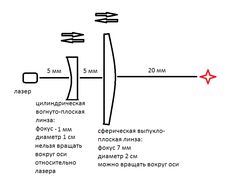
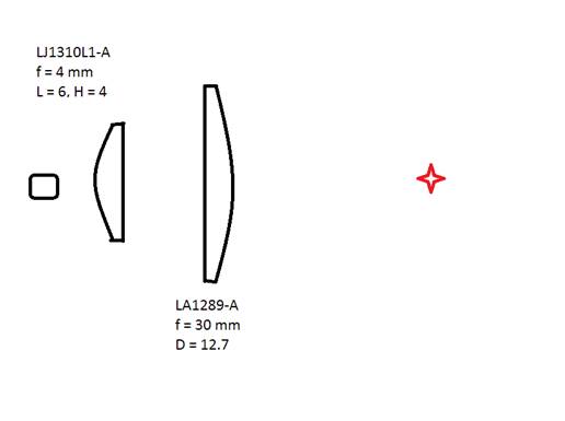
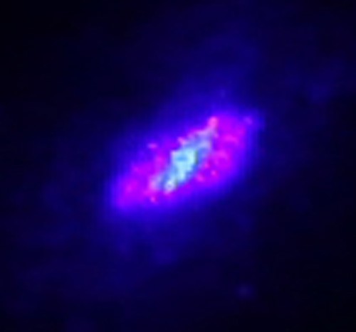
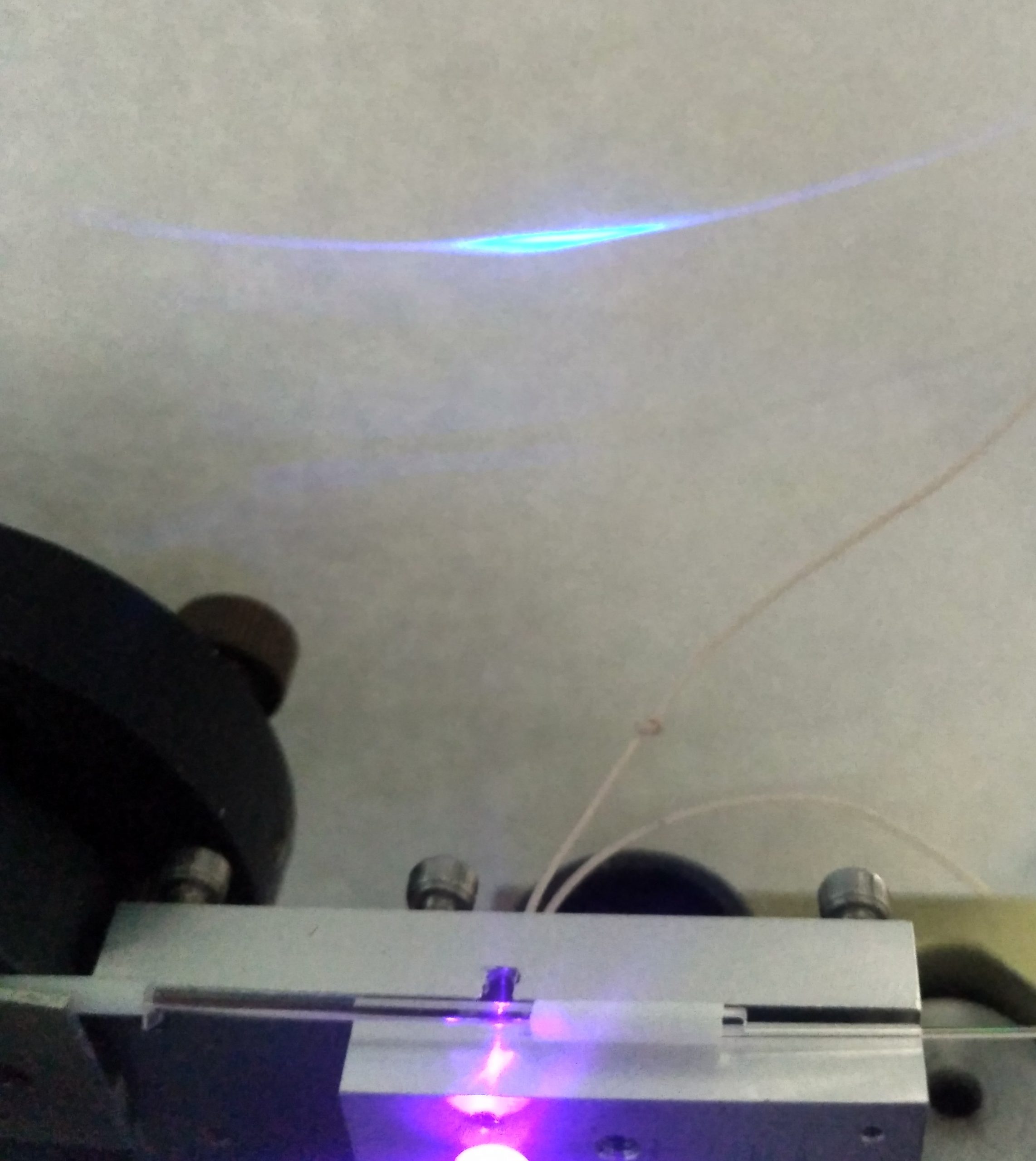
New experiments with decreasing a laser beam spot
using of a cylindrical flat convex lens + aspherical lens.

Measuring the laser beam angles (fast / slow axes). Checking proportions
Final result and a live demo of the improved laser lens system
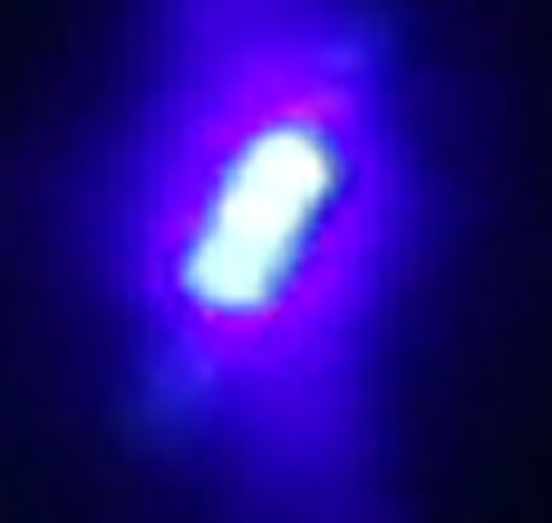
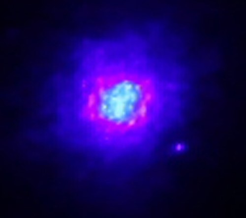
New improved laser beam spot
As a result, laser beam density will increase 4-5 times.
The initial laser beam spot is 85*130 = 11050
while the laser beam spot now is in the range 30-50 uM and it is a square it means that a final laser beam area is:
30*30 = 900 | 40*40 = 1600 | 50*50 = 2500
that means that a new laser beam area is at least 4-5 times less than it was before.
Price
795$ for an entire laser lens focusing system
More about prism telescope for diode lasers
About a prismatic telescope
Usage of a prismatic telescope:
- To compress the beam size along the fast axis. In this case a more powerful lens may be used to focus the compressed beam; consequently, the spot size in the focus will be smaller.
- To increase the spot size along the slow axis. In this case the beam divergence along the slow axis decreases, and the spot in the focus is less elongated.
Now let’s digitize the work of a prismatic telescope. We are going to see how it compresses a plane-parallel beam, that is usage 1. The same goes for usage 2, but the beam in that case will go in the opposite direction.

The prismatic telescope consists of two prisms made out of glass H-ZLaF2a with an angle of 30о at vertex. The angle of incidence on the first face of the first prism is 0, the magnifying power of the telescope is approximately 4,5 (angularly).

Beams entering the prism. Here, if the beam goes to the bigger base the angle of incidence is considered positive, if the beam goes from the bigger base, it is considered negative.
The beam going out of the prism is compressed by M1 times:
For a telescope consisting of two prisms the beam is compressed by M2 times:
where: n – refraction index of the prism (for glass H-ZLaF2A n = 1.82 at 445 nm). For the rest of the data, please, see the second fig. above.

Compression of a beam by one prism (red curve) and by two prisms (blue) of glass H-ZLaF2A with an angle of α=30о.
The glass H-ZLaF2A absorption ratio at a wavelength of 445 nm is about 0.02 cm-1 (e base). It means that absorption of beams by two prisms will be 1-3 %. But because of the high refractive index of glass (n ≈ 1.82) the reflection loss on uncoated faces can be very high.

Transmission characteristic of the telescope made of two prisms with uncoated faces.
The blue curve corresponds to the radiation polarization in the plane of incident and refracted rays, and the red curve corresponds to that in the perpendicular plane.
- To use the telescope made of uncoated prisms for beam compression along the fast axis is possible only in the case when the polarization of the diode radiation is directed along the fast axis and only with a compression ratio of 3-5. In this case the power loss will be 1520%. If the diode radiation is polarized along the slow axis then the reflection loss on the uncoated faces will be unacceptably large.
- In this case, the other way around, diode polarization along the slow axis is needed. To form a compact spot in the focus 4-7 fold magnification along the slow axis is required to ensure minimal refraction losses on uncoated faces (15-20 %).
The main task when working at the maximum power is to obtain a minimum focal spot with a minimum focal depth of:
- at least 1 mm
- 4-6 mm
- 3 mm
Diode radiation divergence, obtained 1 or 2 years ago: 
fast slow axis
Let’s consider theoretical possibilities. Since the radiation quality along the slow axis is much worse than along the fast axis, it is the quality along the slow axis that imposes limitations on the focal length. The estimated radiation fraction going into the Θ angle (in degrees, full angle):

As seen from this chart, 80 % of the power goes to an angle of 7.2о, and 90 % of the power to an angle of 8.8о.
The beam waist width can be estimated by the formula:
where: w0 is the beam waist width at focus, Θfoc is a full angle of the focused radiation divergence (at a certain given level), z is an axial coordinate measured from the focal position.
Angle Θfoc depends on w0 :
where: wLD and ΘLD is the size of the emitting area of the laser diode (here, along the slow axis) and ΘLD is the laser diode radiance divergence (same direction). If by the waist length Lw we mean the the length of the segment where the waist width is no more than two times the focus waist width w0, then:
and for the width at focus:
If the radiating aperture width wLD along the slow axis is around 230 µm , then:
to obtain a focus depth of no less than 1 mm, the waist width w0 should be:
120 µm– at a level of 80 %
133 µm – at a level of 90 %
to obtain a focus depth of 4-6 mm: w0 = 240 – 294 µm (level of 80 %), or w0 = 266 – 326 µm (level of 90 %).
The corresponding values for a focus depth of 3 mm are 208-230 µm.
More tests will be made with the following lenses
| Item code | Description | Diameter(mm) | EFL(mm) | CT(mm) | AR Coating 440-450 nm | |
| GP25430 | Fused Quartz plano convex lens | 25.4 | 30 | 10 | N | |
| GP25440 | Fused Quartz plano convex lens | 25.4 | 40 | 6.6 | N | |
| GP25450 | Fused Quartz plano convex lens | 25.4 | 50 | 6 | N | |
| GF50F10-36 | D-ZK3 aspheric lens | 5 | 10 | 2 | Y | |
| GF50F6-37 | D-ZK3 aspheric lens | 5 | 6.2 | 3.5 | Y | |
| GF50F8.0-50 | D-ZK3 aspheric lens | 5 | 8 | 2.3 | Y | |
| GF55F8.8-10 | L-BAL42 aspheric lens | 5.5 | 8.8 | 2.4 | Y | |
| GF60F9.8-20 | D-ZK3 aspheric lens | 6 | 10 | 2.25 | Y | |
| GF6.33F4.05-94 | D-ZK3 aspheric lens | 6.33 | 4.05 | 3.3 | Y | |
| GF63F10-09 | L-BAL42 aspheric lens | 6.35 | 10 | 3 | Y | |
| GF6.35F6.43-75 | D-ZK2N aspheric lens | 6.35 | 6.43 | 3.11 | Y |
| GF7.2F6.24-024c | D-ZK3 aspheric lens | 7.2 | 6.24 | 5.36 | Y |
| GF10F8.0-80 | D-ZK3 aspheric lens | 10 | 8 | 3.43 | Y |
Since the diode divergence along the fast axis is too wide for a conventional collimating lens to be used, it is possible to reduce the divergence with a cylindrical lens. The simplest thing to use as a cylindrical lens is a piece of quartz-quartz fiber with its outer polymer shell removed. Of course, this “lens” will introduce aberrations, but as the beam quality of the laser diode along the fast axis is much better than along the slow one, so we can sacrifice part of the quality along the fast axis. Befind it, you can use a couple of conventional lenses.
This optical schematic shows the ray paths:

the fast axis,

the slow axis.
The calculations assumed:
quartz-quartz fiber with a core diameter of 600 microns, sheaths – 800 microns, NA=0.22
two identical, glass, plano-convex, f=10 mm lenses following one after the other
Results:
A focused spot:
If you position a cylindrical “lens” so that it collimates radiation along the fast axis as much as possible, then the foci along the fast and slow axes behind the third (focusing) lens will be greatly spaced-apart, and it will be difficult to form a not-too-elongated spot. To form a little elongated spot, it makes sense to move the cylindrical lens (fiber) closer to the laser diode so that the radiation along the fast axis is divergent at the end of it. The figures just show this case. It corresponds to the distance from the diode emitting aperture to the fiber of 0.08 mm. Is it possible to posotion the fiber so close?

The spot shape at the place of its “best compactness” (left) and the spot section profiles (right, in mm along the lower axes, and in relative intensity units along the lateral axes).
Although, the “fiber lens” catches the entire laser diode radiation, some of it is reflected. Estimations show that the reflected light proportion can be around 15%.
Aberrations of the semicylindrical lens
The task is to determine the collimation possibilities of the laser diode radiation along the “fast axis” using a semicylindrical lens mounted on the diode body. There is a glass plate, ~ 400 μm thick, between the diode and lens. For a first approximation, it changes the “optical” distance between the diode and lens by 0.13mm. This distance varies insignificantly along the entire numerical aperture of the diode, so we’ll consider it to be the identical in the same approximation; in this case, the window might be ignored. The distance between the edge of the housing and the diode is taken equal to 1.0 mm.
The task parameters are shown in fig.1. The beam emanating from the diode end hits the flat surface of the semicylinder at the QH angle after its refraction propagates at the QL angle and leaves the cylindrical surface at the QQ angle. The АА(QH) astigmatism value corresponds to the distance from the local focus (~hh*ctg(QQ)) to the diode end.

RR is the fiber radius; nn is its refraction index
HM – half-height of the flat surface
LL – distance from the flat surface of the semicylinder to the diode end
AA (HH) – astigmatism value of the semicylinder
The AA (0) and AA (HM) parameters are the most interesting. In the approximation of geometric optics, they are calculated according to the following ratios: вставить в рис.1
Fig. 1 – The beam propagation scheme in a quartz semicylinder and the main ratios in the approximation of geometrical optics. The quartz refraction index is λ = 440 nm.
It should be pointed out that the astigmatism of the wide-angle lens АА(НН) in fig. 1 depends monotonely on the angle of incidence and increases rapidly as one approaches the lens edge НМ (the НМ height is always less than the RR radius). In this connection, the astigmatism range is completely characterized by the AA values at the edge AA (HM) and in the center of the lens АА(0). Therewith, АА(НМ) > АА(0), see below. The astigmatism value in the lens center is intermediate between the maximum АА(НМ) and minimum АА(0) values.
In certain cases, when the lens thickness is close to the cylindrical surface radius the rays near the lens edge undergo total internal reflection, which imposes appropriate restrictions on the size of the light aperture. The numerical analysis showed that to eliminate this effect, the ratio HM < 0.9RR is quite acceptable and will be considered satisfied below.
The calculation was carried out in the Mathcad program, the file Astigmatism of plano-cylinder lens (1-2022).xmcd. is attached.
First of all, as an example let’s consider a flat-cylindrical lens with a radius of curvature of 0.5 mm, made of a fiber of 1 mm. Further on, the distance from the diode end to the flat lens surface will be taken equal to 0.87 mm, which corresponds to a physical distance of 1mm. The half-height of the lens HM is a changing parameter dependable on the degree of the fiber trimming. 
Fig 2. The astigmatism of the edge of a 1mm-flat-cylindrical lens when its cross size 2*HM varies from 0.2 to 0.9 mm (the numerical aperture from 0.23 = 0.2/0.87 to 1.03 = 0.9/0.87).
When the cross size increases the lens becomes thicker, and its focus (for extreme rays) passes through the diode end at НМ = 0.25 mm, which corresponds to the numerical aperture of 0.29. If the focus is befind the diode end (НМ < 0.25), the extreme rays (the rays at the lens edge) will be divergent, and the focus will be behind the diode, as shown in fig. 1. If the lens focus is in front of the lens edge (НМ > 0.25), the rays behind the lens will converge, and the AA (HM) value will be negative.
Approximately, the same situation will be observed for the astigmatism in the center of the lens АА(0), as shown in fig. 3. The astigmatism is changing to HM < 0.4 comparatively slowly, after that it quickly increases. In this case, the focus of the lens with a cross size of 0.9 mm is almost at the diode end.

Fig. 3 – Fig. 2 – The center astigmatism of a flat-cylindrical lens with a diameter of 1 mm when its cross size 2*НМ is changing from 0.2 to 0.9 mm (the numerical aperture from 0.23 = 0.2/0.87 to 1.03 = 0.9/0.87).
Thus, the initial fiber diamter of 1 mm is too small, and should be increased. Figs. 4-7 show the curves of the astigmatisms АА(НМ) and АА(0) for the initial fiber diamters of 1.5 and 2.0 mm.

Fig. 4. The edge astigmatism of a flat-cylindrical lens with a diameter of 1.5 mm when its cross size 2*НМ is changing from 0.2 to 1.0 mm (the numerical aperture from 0.23 = 0.2/0.87 to 1.15 = 1.0/0.87).

Fig. 5. The center astigmatism of a flat-cylindrical lens with a diameter of 1.5 mm when its cross size 2*НМ is changing from 0.2 to 1.0. mm (the numerical aperture from 0.23 = 0.2/0.87 to 1.15 = 1.0/0.87).
Here, it is important to point out that with small cross sizes of the lens the edge- and center astigmatism is almost the same, i.e. at small numerical apertures the entire beam will be well focused (with an additional aspheric lens, for example) along the fast axis, although, due to the astigmatism, the focuses along the fast and slow axes will be in different planes. The astigmatism at the edge and center of the lens “skitter away” at a numerical aperture of 0.6…0.7, НМ > 0.3, that is why the beam will be diffused even when focusing with an aspheric.
A similar situation arises when the fiber diameter is increased to 2 mm (it looks rather like an optical tube, not fiber).

Fig. 6. The edge astigmatism of a flat-cylindrical lens with a diameter of 2.0 mm when its cross size 2*НМ is changing from 0.2 to 1.0. mm (the numerical aperture from 0.23 = 0.2/0.87 to 1.15 = 1.0/0.87).

Fig. 7. The center astigmatism of a flat-cylindrical lens with a diameter of 2.0 mm when its cross size 2*НМ is changing from 0.2 to 1.0. mm (the numerical aperture from 0.23 = 0.2/0.87 to 1.15 = 1.0/0.87).
Altogether, the overall trend is as follows: when the original cylinder diameter increases the astigmatism decreases as well as the difference in the astigmatism degree at the edge and center of the lens, however, the collimation degree along the fast axis worsens. As an example, figs. 8 and 9 show the dependence of the divergence angle QQ (fig.1) at the lens edge on its cross size 2*HM for the initial diameters of 1.5 and 2.0 mm.

Fig. 8 The divergence angle QQ (see fig.1) at the lens edge depending on its cross size 2*HM for the initial fiber diameter of 1.5 mm.

Fig. 9. The divergence angle QQ (see fig.1) at the lens edge depending on its cross size 2*HM for the initial fiber diameter of 2.0 mm.
According to figs. 8 and 9, a fiber lens with a diameter of 1.5 mm reduces the divergence along the fast axis, approximately, by two-three times, while a fiber lens with a diamter of 2 mm does it by one and a half – two times.
In general, the most optimal is the use of a fiber with a diamter of 1.5 mm at 2*НМ = 0.8, which gives a numerical aperture of 0.92; at that, the maximum astigmatism АА(НМ) is 2.0 mm, and the center astigmatism АА(0) = 1.4 mm, i.e. the difference is about 0.6 mm. In this case, the divergence along both axes is almost the same, but the astigmatism is to be compensated.
Let’s estimate the possibility of the astigmatism compensation by tilting a spherical lens,which focuses the light beam on an object after the diode radiation collimation with the half-cylinder. The calculated ratio is presented in the attached program Astigmatism of plano-cylinder lens (1-2022).xmcd for the approximation of thin lenses and paraxial beams. The lens AALENS astigmatism is defined as a difference between the focal lengths in the tangential and sagittal planes. If the spot scale is not changed then the best mutual compensation of the astigmatism corresponds to the ratio AALENS = 0.5(AA(НМ)-АА(0)), since the distance from the fiber to the spherical lens is supposed to be double the focal length, as well as the distance from the lens to the object. The calculation results of the spherical lens astigmatism depending on the qq (degrees) of its slope angle relative to the symmetry axis of the light beam are shown in figs. 10 and 11 for focal lengths of 25 mm and 40 mm, respectively (whereby, the distances from the lens to the object are ~50 mm and ~80 mm).

Fig.10. The astigmatism of the spherical lens with a focal length of 25 mm depending on its slope angle qq (degrees), the lens is made of fused quartz.

Fig.11. The astigmatism (mm) of the spherical lens with a focal length of 40 mm depending on its slope angle qq (degrees), the lens is made of fused quartz.
In general, the compensation of the flat-cylindrical lens astigmatism with a diameter of 1.5 mm even in the paraxial approximation is associated with rather large tilts (slopes) of the focusing spherical lens by an angle of ~10 degrees, which is not quite acceptable when focusing wide-aperture beams. For example, for a beam numerical aperture of 0.16 and a spherical lens focus of 25 mm, a 10 degrees slope will shift the lens surface at the beam edge by 0.7 mm, which will change the focus position in the object area by the same value. As a result, when focusing on an object, the spot will “blur” (diffuse) by 0.7 * 0.16 ~ 0.1 mm. Similarly, for a lens with a focus of 40 mm, the slope will be ~ 8 degrees, the lens shift at the beam edge will be 0.9 mm, and the beam focused on the object will “blur” by ~ 0.14 mm.
Conclusions: the combination of a collimating flat-cylindrical lens on the laser diode body and the subsequent radiation focusing on an object using a tilted spherical lens in the first approximation allows mutual compensation of the aberrations . The lens tilt leads to an additional diffusion of the focused beam size due to the fact that different parts of the tilted lens shift from (or towards) the source, that is why their focal depth will be different. To clarify the actual focal spot size and its transformation when withdrawn from the focal surface it makes sense to calculate the focusing parameters of spherical lenses taking into account the slope angle. According to preliminary estimates, a focal depth of +/-1mm will be achievable at a spot size of 335-400 µm if the laser diode radiation is collimated with a flat-cylindrical quartz fiber lens with a diameter of 1.5 mm and then the light beam is refocused with a spherical lens with a focus of 25 mm.
A study about effectiveness for laser cutting with a bigger fast axis length and with a deeper laser beam focus for fast axis
While doing experiments with cutting in the evening, I noticed that it is the slow axis that always limits us in cutting, in other owls it doesn’t matter how fast you cut along the fast axis, if it’s not about cutting straight lines, then any curly cutting will have a limitation of exactly the size of the spot along slow axis. Since we also have a problem with the quality of the slow axis, I consider the task of working with a single diode meaningless precisely because the spot size along the slow axis is many times greater than the spot size along the fast axis and the depth of focus along the slow axis is also many times smaller.
That is why, I think it is necessary now to evaluate the possibility of combining 2 beams, as we do with the help of a polarizing prism + the possibility of focusing exactly several 3-6-9-12 diodes into one by directing plane-parallel beams onto one focusing lens. In this case, I consider the depth of focus to be acceptable in the region of 5–10 mm, which corresponds to a strip length of 12–20 μm along the fast axis.
The size of the strip on the slow one is not important in this sense, since the depth of focus on the slow one will be no more than 0.2-0.3 mm, which is essentially not important.
The power density is important, the depth of focus is precisely along the fast axis, since with beam superpositions 0 + 90 + 45 + 22.5 + 11.25, etc. at such angles will provide maximum power density, depth of focus, and the fast axis.
The optimal power density for cutting plywood is 50-100 kW / cm^2, however, this power density in itself does not mean anything if the rated power is less
CRITICAL REMARK
In other words, if you have a beam of 70×5 μm and a power density of 1 MW / Cm ^ and the diode power itself is 5.9 W,
then such a laser will cut plywood worse than the one with a beam size of 250 μm x 15 μm, despite the fact that the power density in this embodiment is already about 150 kW / cm ^ 2, and the diode power itself is 7.5W
In this regard, it can be postulated that the power density in the range of 50-100 kW / cm^2 is more than sufficient, and it is necessary to have a large focus and increase the nominal power, superimposing one beam on another, getting something like a snowflake.