In this article, we explain how to make a g-code for laser engraving using Inkscape software and Endurance plugin and JTech photonics plugin.
Watch all video footages about the generation of a g-code
Table of contents
Step 1. How to convert a pixel image to a vector one
Step 3: How to convert a vector image to a Gcode file
Step 5: How to run an Endurance Plug-in «Endurance Laser» for Inkscape
Step 1. How to convert a pixel image into a vector one
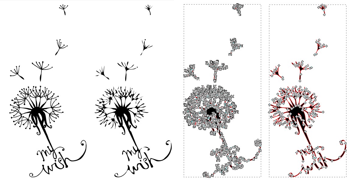
Please note: a vector image is not a precise copy of the pixel picture but a set of curves for further processing.
To convert a pixel image to contours we use InkScape (https://inkscape.org/ru/download/).
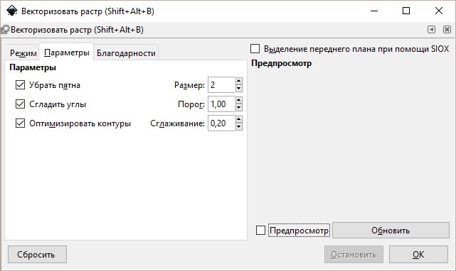
To do so import your pixel image to InkScape, then select it in the InlSkape window, click “Contours” in the program menu, and then “Vectorize raster”, or use the combination of Shift+Alt+B keys.
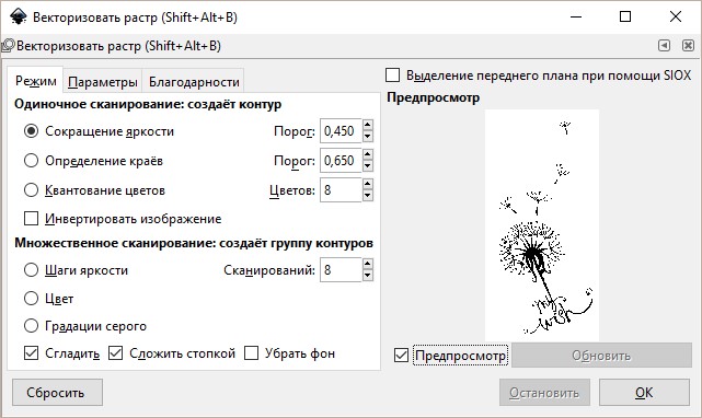
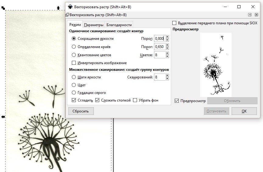
You will see three filters in the opened “Mode” window. The first one is “Brightness Reduction”. This filter uses the sum of the red, green and blue components of the pixel (i.e. shades of grey) as an indicator and chooses to interpret it as black or as white. The brightness threshold may be set from 0,0 (black) to 1,0 (white). The higher is the value the fewer pixels are taken as “white”, resulting in a darker image.
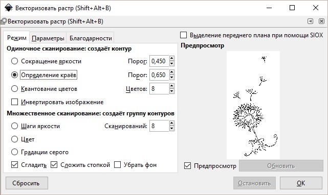
The second filter is “Edge Detection“. This filter creates an image even less similar to the original than the one created by the first filter but it accentuates the curves, fully ignored by the other two filters. The threshold value (here: 0,0 – 1,0) regulates the brightness threshold between the adjacent pixels, depending on which the adjacent pixels will or won’t partake in the contrast edge formation, thus becoming or not part of the contour. Actually, this parameter determines the brightness (thickness) of the edge.
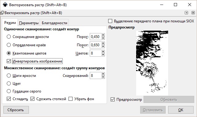
The third filter is “Color Quantization“. The image processed by this filter is quite different in comparison with the previous two but it is also useful. It does not show the brightness or contrast isoclines but it detects the edges where the color changes even if the adjacent pixels have the same brightness and contrast. This filter parameter (number of colors) defines the resulting number of colors as if the raster image were colored. Then the filter assigns a pixel as black or white depending on the parity of the color index.
The “Parameters” toolbar gives additional options to process a vector image. For example, we recommend clearing of the “Angle Smoothing” checkbox to accentuate finer details.
Note for beginners: The processed vectorized image sits above the original raster picture and is a separate, independent contour object. This object is selected by default. You can move it using a mouse or arrow keys. You can edit the nodes of the object using the “Node tool”.
Just try all three filters to compare the results of image processing. Every image is an individual. In every case, the filters work in a different way producing different effects. To achieve the best result choose among the three filters that one, which makes a contour of the optimal quality.
After vectorization we recommend using contour simplifying, to reduce the number of nodes. You will find this function in the main menu toolbar – “Contours” – “Simplify”. Or just use the key combination Ctrl+L. Nodes reduction will make it easier to edit the resulting vector image.
Referencies:
- How to convert a raster to contours https://inkscape.paint-net.ru/?id=30
- Gcodetools – extensions for Incscape https://www.cnc-club.ru/gcodetools
- Inkscape tutorial https://inkscape.org/ko/doc/advanced/tutorial-advanced.ru.html
Notes: 1. Gcodetools and Inkscape are free and open source software licensed the GNU GPL, free for commercial use as well. Both programs are crossplatformal and have distributives for Windows, Linux и MacOS.
Step 2: Fixation of an item for engraving to a 3D printer table and positioning it in the coordinates of InkScape
Before laser engraving of an item you need to know:
1. You need to fix the item to the working table of your 3D printer or engraver to prevent it from shifting during engraving if the working table vibrates too much. You can use for this:
1.1. Grips, clips, clamps of all kinds;
1.2. Double stick tape or mats;
1.3. Rubber bands;
1.4. A couple of magnets to be placed on and under the working table.
Note: All those holders must be placed off in the engraving field.
2. If your item is transparent or semitransparent use an underlay for the item (e.g. a piece of plywood), otherwise the laser beam will go through the item and damage the 3D printer/engraver table. Use an underlay when cutting as well to protect the table surface from damage at the final stage.
3. To engrave the vector image precisely at the chosen area of the item you need to:
• Correlate the vector image position coordinates and those of the engraved item with the machine coordinates of the 3D printer;
• Correctly position the image in the Inkscape coordinates. So, let’s do it by steps:
1.1. To find the image and the item position in the machine coordinates of the 3D printer we need to choose a certain marking point and pinpoint it to use hereafter for determination of the working area coordinates and positioning of the engraved item on the 3D printer table.
1.2. With a Wanhao 3D printer, we recommend using the right bottom (the nearest to you on the right) corner of the 3D printer table as a marker point (marker).
1.3. Then we determine the machine coordinates of the marker (right bottom corner of the table), for which we need to:
1.3.1. Turn the 3D printer on.
1.3.2. Perform auto-detection of the axes coordinate origin: go to the printer settings turning the knob on the printer control box, select «Quick Settings» and «Home All». The commands here and elsewhere are given for a Wanhao Duplicator i3 3D printer.
1.3.3. Raise the laser along Z axis up to the level necessary for engraving (it depends on the laser focus length. For more info see “Laser focus length instruction”). For a start set Z coordinate at 40 cm. For coordinate positioning use the printer control box. In the settings go to the «Position» -> «X Pos. Fast», or «Y Pos. Fast», or «Z Pos. Fast», and change the coordinate value turning the knob.
1.3.4. Using step-by-step zooming, move the laser along the axes to aim the laser beam on to the right bottom corner of the printer table (our marker point). The marker point coordinates will show up on the screen. To check the focusing accuracy we need to turn the laser on. Before it put on safety goggles. Observe the safety rules while working with the laser! Work only WITH YOUR GOGGLES ON! Using the control box, turn the laser on and go to the settings, -> «Fan speed» -> «Set Fan Full», and tune the focus anew, if necessary. To turn the laser off we can use «Turn Fan Off» or an additional red ON/OFF button on the upper part of the Wanhao 3D printer frame.
1.3.5. Write down the marker point coordinates.
1.4. E.g. Suppose, the marker point coordinates are: X=200, Y=75. Fix the engraved item in the right bottom corner edge to edge. If our item size is 100х100 mm, and the engraving image – 60х60 mm, and we want to position the engraving in the middle of the item, then the left bottom corner of the engraving (of the image) will be X=120 and Y=95. To find it: X= 200 – (100-60)/2 – 60, а Y= 75 + (100-60)/2. We’ll need these coordinates further on in p.2.2.2. Try to draw and calculate them by yourself.
2. Now we need to position the vector in the coordinates of Inkscape. To do so:
2.1. Set the page size (i.e. the working field of the 3D printer) in the working field of the document:
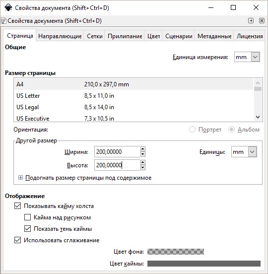
2.1.1. Go to «File» à «Properties» à «Page size» (or use the key combination Shift+Ctrl+D).
2.1.2. In «General» set «Measure unit» in «mm».
2.1.3. In «Page size» go to «Other size» –> «Units», change to «mm», and set «Width»: 200, «Height»: 200. Note: 200х200 mm is the coordinate range of the Wanhao 3D printer head movement.
2.2. We also need to position the engraving image and set its required size in InkScape. To do so:
2.2.1. Set the size in the “W” (width) and “H” (height) icons in mm. The lock icon (in operation mode) will save the proportion if you change the image.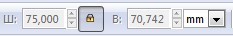

Step 3: How to convert a vector image to a Gcode file
First of all, you need a ready vector image. Here are key requirements for the vector image to make engraving of the best quality:
• The vector should have only one image layer (sometimes it has a number of image layers with different details).
• It should not have too many fine features (less than 0,5 mm), otherwise, the laser will burn through the engraved item, because it will work too long over one fine detail.
• It should not have too many nodes, otherwise Gcode generation will go on for hours. Use the function of contour simplifying, to reduce the number of nodes or edit the image manually.
For the detailed description of the vector preparation go to the Engraving Instruction. Step 1. link.
1. At first:
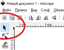
1.1. Select the vector image, prepared for engraving, using the selection and transformation tool (the first one at the top of the toolbar with a black arrow), or pressing S or F1 key.
1.2. With the mouse or arrow keys position the selected object in the X-Y axes according to the coordinates of the engraved item position on the working table. It is also possible to set the necessary coordinates in X and Y icons of the upper command line. 
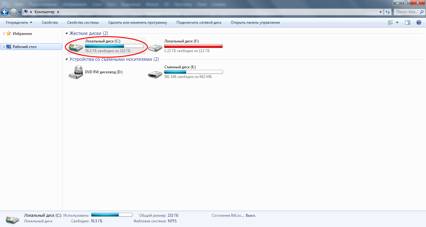
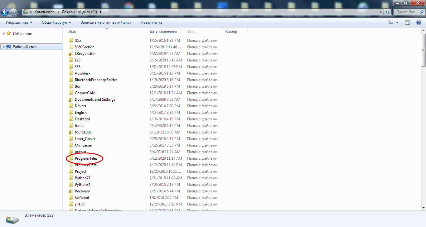
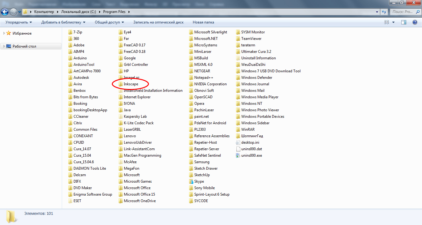
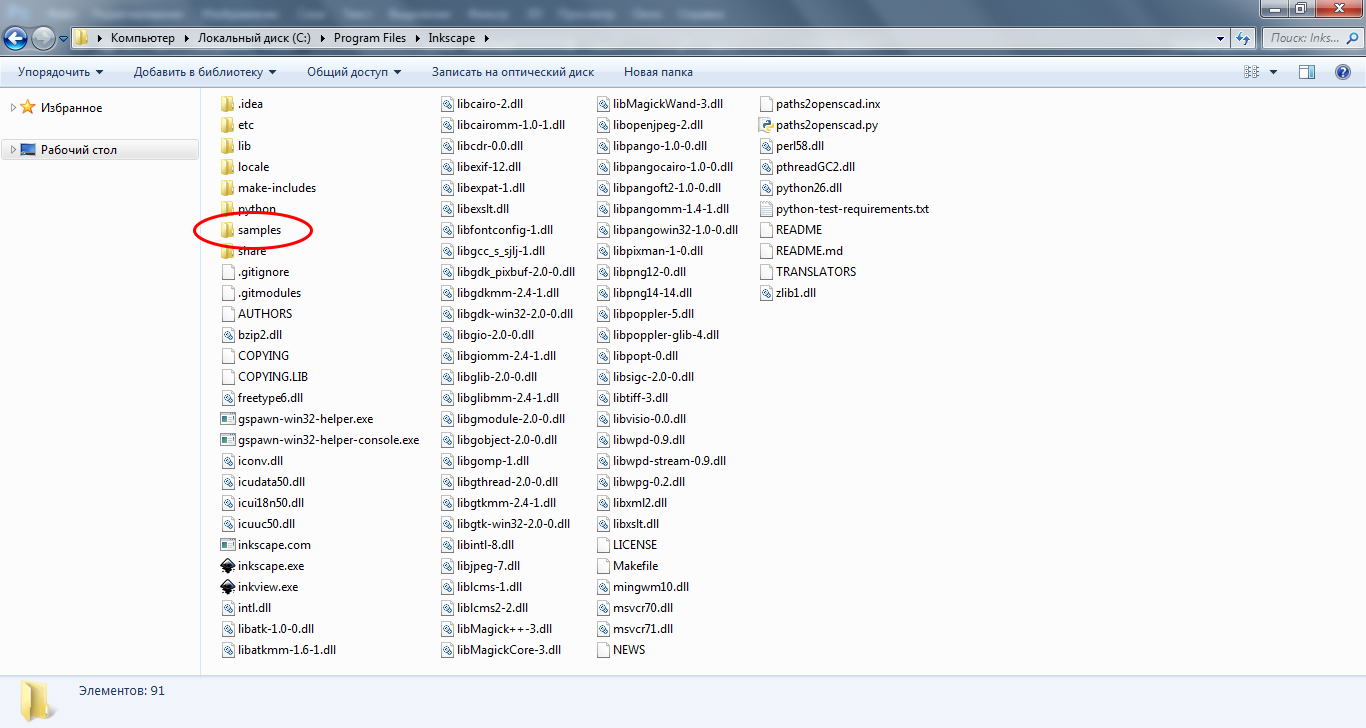
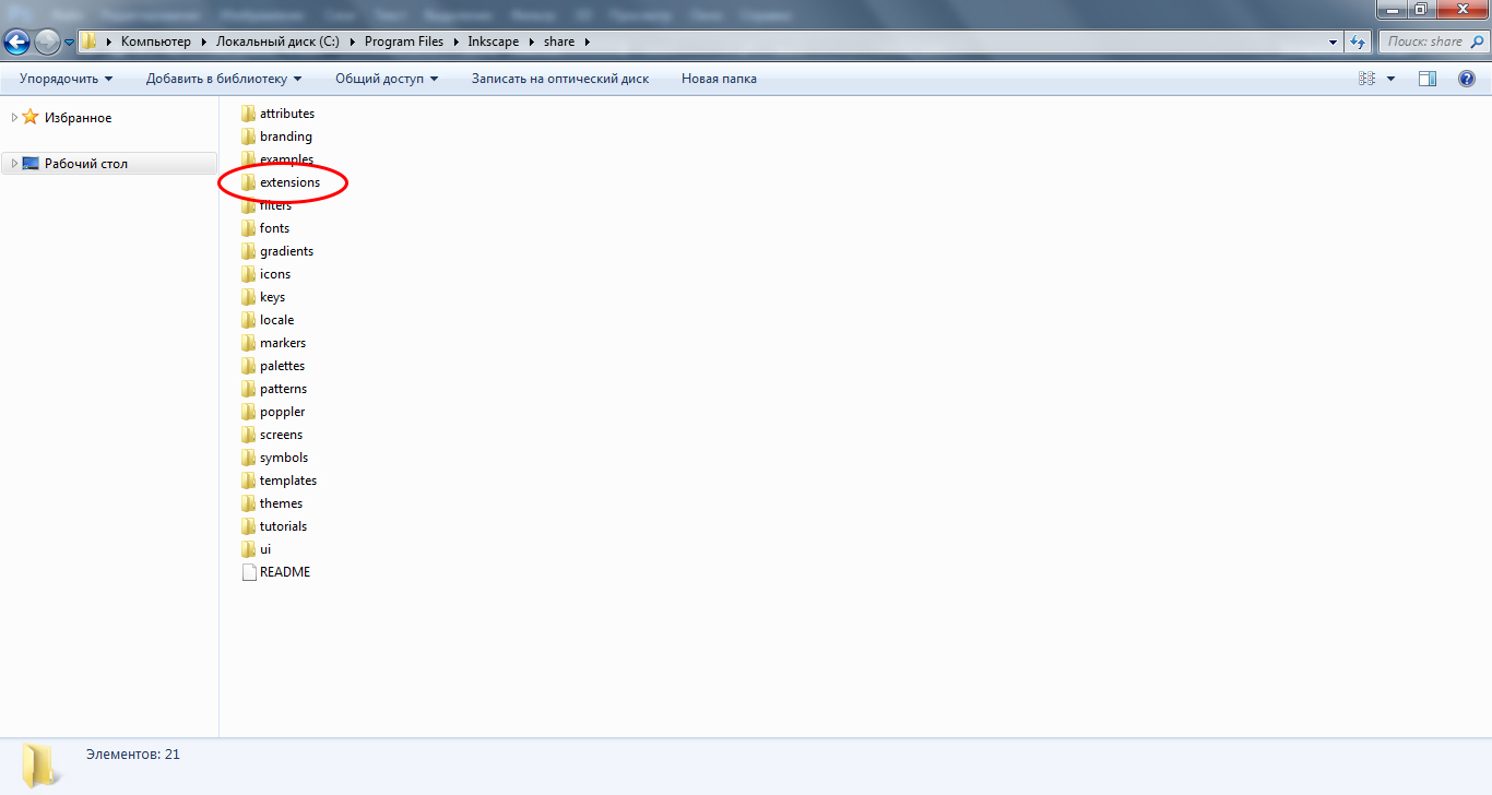
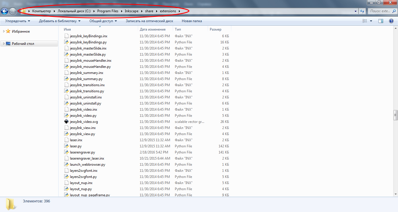
2.1. Said plug-in files («laser.inx», «laser.py») must be present in the program directory: C:Program FilesInkscapeshareextensions». For your convenience, we attach these files to be downloaded to the Instruction.
2.2. Click “Extensions” in the “Menu”, then «Generate Gcode» and «J Tech Photonics Laser Tool…» 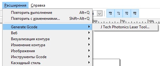
2.3.1. Laser On and Off commands, used for our printer (e.g. M106 and M107, correspondingly, for a Wanhao 3D printer).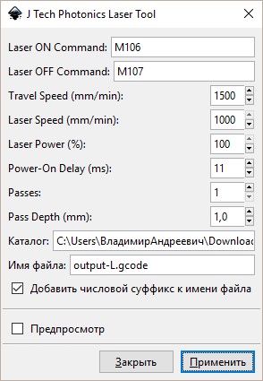
2.3.2. Movement speed (when the laser is off).
2.3.3. Burning speed (when the laser is on).
2.3.4. Delay time before moving (burning) in msec. after the moment of laser activation at the beginning point of each contour.
2.3.5. Number of passes during image engraving.
2.3.6. Burning depth in mm in one pass. This parameter is taken into consideration in Gcode when the number of passes is more than one. After every pass, a new command is added to move down the laser by this value (to save the same laser focusing).
2.4. Save the Gcode file in an appropriate catalog. The program will keep it ready for use for the next time.
2.5. To activate the plug-in click “Apply”.
2.5.1. If a plug-in failure notification pops up, edit a little the vector image again and start the plug-in once more. Or choose another plug-in (for instance «GcodeTools»).
2.5.2. For your convenience add a few useful commands to your Gcode. Open your Gcode in Notepad++ (https://notepad-plus-plus.org/).
2.5.2.1. At the beginning of the code insert «G28 X Y» (Go to origin only on the X and Y axes). It is important in case of mechanical displacement of the printer head. The «G28» (Go to the origin on all axes) command will reset the axes to zero.
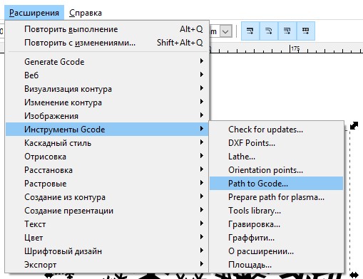
3. In case of the first plug-in poor performance use another one: «GcodeTools».
3.0. Open «Extensions», then «Generate Gcode», and «Path to Gcode».
3.2. Go to the third tab: «Parameters…».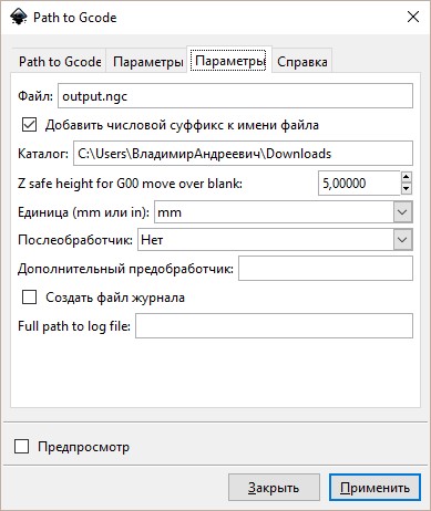
3.2.1. Save the code in the program catalog, to avoid entering it again next time. 3.3. Go back to the first tab «Path to Gcode» and click “Apply”.
3.4. Open the obtained code in Notepad++ (https://notepad-plus-plus.org/) and make a few replacements in the code:
3.4.1. Delete all the upper lines before the words «Start cutting path id:…»
3.4.2. At the beginning of the code insert «G28 X Y» (Go to origin only on the X and Y axes). It is important in case of mechanical displacement of the printer head. Note: The command «G28» (Go to the origin on all axes) will reset the axes to zero.
3.4.3. Set the cursor at the beginning of the file and press the key combination Ctrl + H. In the dialogue window “Replace” go to the settings of “Seek mode” and select “Extended (r, n…».
3.4.4. Replace «(» for «;(»
3.4.5. Replace «G00 Z5.000000» for «G4 P1 n M107;»
3.4.6. Replace «G01 Z-0.125000» for «G4 P1 n M106;»
3.4.7. Replace «Z-0.125000» for «» (i.e. delete еeverywhere «Z-0.125000»).
3.4.8. Replace «F400» for «F1111» (i.е. select the right engraving speed; 1111 is a good speed).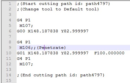
3.4.9. Please mind, in this Gcode, we do not set Z coordinate (laser height). We’ll set it when we start the laser.
3.5. This is what the edited Gcode look like:
4. Our Gcode is about ready to be used in a 3D printer or engraver with an L-Cheapo laser. Program error and failures do happen, so here are our guidelines for bug fix:
3.1. The plug-in «J Tech Photonics Laser Tool» sometimes misses spaces before “F” in the Gcode file lines. E.g. «G0 X167.747 Y97.2462F500.000000». To fix this error manually replace «F500» for « F500» (inserting a space in the quotes before F).
3.2. The plug-in «GcodeTools» sometimes creates an empty file at the end. To fix that go to the “Contour” menu, “Contour the object” and repeat Gcode generatoin. 4. Recommendations: 4.1. For Gcode visualization use: Basic CNC Viewer.
Step 4: Printing and Burning.
After turning on the printer perform auto-detection of the axes coordinate origin (see Step 2, p.1.2.2).
Before engraving start, it is necessary to manually set the laser height Z on the printer if it is not within the generated Gcode.
The optimal height of Z is the one, at which the laser beam is focused on the surface of the engraved item.
On the upper frame of the Wanhao 3D printer, there is a special red button to turn on and off the laser. Before turning the laser on always wear safety goggles!
Put them off only after turning the laser off!
ALWAYS OBSERVE THE SAFETY RULES when lasing. ALWAYS WEAR SAFETY GOGGLES when the laser is on. Useful:
1. The command M18 (Disable all stepper motors) unblock the working table. (When it is blocked you cannot move it). This command is useful at the end of Gcode performance to manually move up the table.
Step 5: How to run an Endurance Plug-in «Endurance Laser» for Inkscape
Select a vector image (a set of contours) with the selection and transformation tool (a black arrow).
FILLS
Start with “Contour object.”
Next, select the plug-in extension «Right G-Code» and then «G-Code …».
The first tab: basic code and commands set.
The second tab: the setting of the curves and lines approximation accuracy with G-code commands.
The third tab: Hatching settings. Angle: Hatching angle in degrees from the horizontal axis counterclockwise
The fourth tab: Display settings. Warning: in this version, the file with the results is overwritten when the plug-in starts anew.
Two radio buttons Process and Generate:
Process: Only contours – process the G-code of the image contours
Process: Only fills — a process the G-code of the image fills
Process: Both contours and fills
Generate: Only lines – display all the processed lines (under the G-code)
Generate: Only G-code – write the processed G-Code to a file
Generate: Both lines and G-code
The result – the fills should be converted into the G-code if it was not present in the plugin settings.
Note: To create a stamp cliché:
• the vector version of the stamp imprint should be mirrored;
• create an outer circle for the stamp imprint, which will be burnt through for further cutting out of it a stamp.
Where to upload plugins for Inkscape
Download Endurance Plug-in «Endurance Laser» for Inkscape
High-quality standard
Multi-level testing system.
Industrial components.
Ultra reliable
The guaranteed duration of the continuous operation ~48-72 hours.
True continuous power output
Our products have the rated power output as advertised – unlike Chinese analogues.
TTL mode
Can be turned on and off with 3.5-24V.
Variable power output.
Plug and play
Universal and compatible mount.
Compatible with most 3D printers and CNC machines.
Friendly return policy
Do not like the laser?
Simply return within 30 days and get a full refund.
Real-time advice
We assist and give advice by Phone / Email / Facebook messenger / Telegram / Whatsapp / Viber.
Professional support
We help to install and tune the laser. We offer qualified after-sales support.
Everything you need
We ship everything you need in one parcel to get started.
Immediate delivery
We ship all units within 4-24 hours. DHL express delivery allows you to get the package in 3-5 days.
Lifetime warranty
All our lasers are tested and could work up to 10000 hours.
Upgrade option
Do you have an old model? Upgrade your unit with more powerful one.