
Q-SWITCHED PULSED FIBER LASER(MFP100W-300W)
Contents
Preface
Thank you for using the Q-Switched Pulsed Fiber Laser (MFP100W-300W) Series products from Maxphotonics. We compile this document for you in order that the laser is used and maintained properly. Due to the limited level of the translaters, coupled with time constraints, there are some careless mistakes in this document, and your understanding will be much appreciated. Thank you again for using Maxphotonics’ products.
Please take time to read and understand this User’s Guide and familiarize yourself with the operating and maintenance instructions before you use the product. We recommend that the operator read the Section titled “Safety Information” prior to operating the product.
This User’s Guide should stay with the product to provide you and all future users and owners of the product with important operating, safety and other information.
We identify the parts to which you need to pay special attention in the document with underscore. Please notice those information to prevent the unnecessary damages.
Characteristic Explain
Maxphotonics’ Q-Switched Pulsed Fiber Laser (MFP100W-300W) Series are Class 4 laser products and are designed and tested with safety. By following this User Guide and applying sound laser safety practices, it will be a safe and reliable device.
Laser light exhibits unique characteristics that may pose safety hazards. Therefore, the laser light can’t be normally associated with other light sources, and all operators and people near the laser must be aware of these special hazards.
In order to ensure the safe operation and optimal performance of the product, please follow all warnings and safety instructions in this guide during process of operation, maintenance and service.
For ensuring the safety of operators, operators are urged not to open the equipment privately at all times. There are no user serviceable parts, equipment or assemblies associated with this product. Lasers of unauthorized disassembly shall not be subject to warranty.
Safety Conventions
All safety warning symbols during operating process of the laser include:
WARNING :
Refers to a potential Electrical Hazard to human body. It requires a procedure that, if not correctly followed, may result in bodily harm to you and/or others. Do not proceed beyond the WARNING sign until you completely understand and meet the required conditions.
CAUTION :
Refers to a potential hazard on product. It requires a procedure, that, if not correctly followed, may result in damage to the product or components. In order to ensure normal use of equipment, do not violate the requirement of the CAUTION sign.
General Safety Information
NOTE :
This device is classified as a high power Class IV laser instrument, and the range of wavelength is from 1060nm to 1100nm. This level of light may cause damage to the eye and skin. Despite the radiation being invisible, the beam may cause irreversible damage to the retina. Laser safety eyewear is not provided with this instrument, but must be worn at all times while the laser is operational. Use appropriate laser safety eyewear when operating this device. The manufacturer of the laser system is responsible for the safety compliance according to the applicable standards and regulations.
Laser Protection
Laser Protection Requirements
You must wear the safety protective glasses while operating the laser, and rationally select the safety protective glasses according to the lasing wavelength of the laser. If the device is a tunable laser or Raman product, it emits light over a range of wavelengths and the end user should confirm the laser safety eyewear used protects against light emitted by the device over its entire range of wavelength.
Laser Protective Equipment Suppliers
Maxphotonics recommends material or equipments provided by following laser protective equipment suppliers for you, including LaserVision USA, Kentek Corporation, Rochwell Laser Industries, etc. All the supplier information is provided by Maxphotonics only for the convenience to use, so Maxphotonics assumes no responsibility for any problem caused by using the products of abovementioned suppliers.
General Safety Instructions
In order to ensure the safe operation and optimal performance of the product, please follow these warnings and cautions in addition to the other information contained elsewhere in this document.
Specular Reflection
There are often numerous secondary laser beams produced at various angles in the output port of the laser. These divergent beams are produced when the primary beam of laser reflects off a smooth surface, and they are called specular reflections. Although these secondary beams may be less powerful than the total power emitted from the primary beam, the intensity may be great enough to cause damage to the eyes and skin as well as surface of materials.
WARNING :
You must exercise caution to avoid/minimize specular reflections as these laser radiations are invisible!
Safety Instructions of Accessories
WARNING :
This device has an output optical head connected to the laser by a fiber cable. Please, be careful dealing with the output head.
Optical Operating Instructions
We strongly recommend that you read the following procedures before operating the laser:
- Never look directly into the laser output port when the power is turned on.
- Avoid positioning the laser and all optical output components at eye level.
- Ensure that all personal protective equipment is suitable for the output power and wavelength ranges of the laser.
- Do not install or detach cutting heads or collimators when laser is active.
- It is forbidden to turn on the laser during the mounting of fiber or cutting head. Carry out commissioning, calibration and focusing at low output power and then increase the output power gradually when the calibrating and focusing work is done. Marking on highly reflective materials is feasible, but you must make the laser out of focus, or else you may damage the laser.
- For collimated outputs, maintaining a clean output lens is essential. Always close (re-cap) the collimator after use. Do not touch the output lens and do not clean it with any solvents. Cleaning with the special solvent and cleaning buds is allowed as described later on in this manual.
WARNING :
Make sure that the individual protective equipment meets the output power and wavelength range of the laser.
Never look directly into the optical fiber or the collimator, and Use appropriate laser safety eyewear when operating this device.
Optical damage may result from failure to comply with the above instructions. Such damage is not covered by the warranty.
WARNING:
Use of controls or adjustments or performance of procedures other than those set forth in this User’s Guide and related documents may result in hazardous radiation exposure.
Electrical Operating Instructions
Q – S wit c hed puls ed f iber las er ( M F P 100W – 300W ) S er ies s upply voltage:220/110VAC。
| Cable Color | Supply |
| BROWN | L |
| BLUE | N |
| YELLOW-GREEN | SHELL |
WARNING :
Make sure the shell of this equipment is properly grounded. Any interruption of the ground loop may result in personal injury.
Make sure that the input AC voltage of the laser is the voltage of the normal AC mains, and wires are connected accurately. Any incorrect wiring method may cause damage to people or instrument.
Before supplying the power to the device, make sure that the correct voltage of the DC power source is used. Failure to use the correct voltage could cause damage to the device.
No operator serviceable parts inside. Refer all servicing to qualified Maxphotonics personnel.
To prevent electrical shock, do not remove covers, detach the laser without permission and damage the relevant signs. Any product with unauthorized dismounting shall not be subject to warranty.
Environment Conditions and Precautions
We strongly recommend that you read the following procedures before operating the laser:
- Do not expose the device to a high moisture/high temperature environment. Install the laser in the cabinet with the function of temperature-humidity control and dust-free.
- Laser Module has three fans at the rear panel for active cooling. Make sure that there is at least 5cm between fan protector and external objects, and with sufficient airflow to cool the device.
- Before switching on the device make sure that environmental temperature and humidity are within a specified range.
WARNING :
Optical damage may result from failure to comply with the above instructions. Such damage is not covered by the warranty.
Routine Maintenance
- Avoid the impaction on the shipper rod of worktable when the laser is working.
- The laser and optical lens are fragile, please handle with care.
- Stop running once device failure, and provide professional treatment.
- Please follow a set sequence of on-off.
- The limitation on surface of marking machine is within the working area.
- Keep the device clean and indoor.
Safety Labels and Labeling Locations
The following shows the pictures of tags and their positions on the product:
Additional Safety Information
For additional information regarding Laser Safety, please refer to the list below:
Laser Institute of America(LIA) 13501 Ingenuity Drive, Suite 128
Orlando,Florida 32826
Phone:407 380 1553,Fax: 407 380 5588
Toll Free:1 800 34 LASER
American National Standards Institute
ANSI Z136.1, American National Standard for the Safe Use of Lasers (Available through LIA)
International Electro-technical Commission IEC 60825-1,Edition 1.2
Center for Devices and Radiological Health
21 CFR 1040.10 – Performance Standards for Light-Emitting Products US Department of Labor – OSHA
Publication 8-1.7 – Guidelines for Laser Safety and Hazard Assessment. Laser Safety Equipment
Laurin Publishing
Laser safety equipment and Buyer’s Guides
Property Introductions
Product Description
Q-Switched Pulsed Fiber Laser (MFP100W-300W) Series are maintenance- free fiber lasers based on the Q-switched technology and MOPA. These lasers deliver light whose emission wavelength is centered at 1060nm and peak power is up to 10KW or above. The light is guided to the work piece via a flexible metal-sheathed fiber cable. The laser’s running parameters are set by the user’s special controller via a DB-25 interface.
Main Features:
- Short optical pulses, high peak power, a wide range of PRR.
- Superior reliability, long lifetime.
- No shadow or virtual open circuit phenomenon when processing on special materials.
- Universal DB-25 interface.
Applications:
- Industrial applications
- Scientific research
Laser Model Designation Codes
| Model | Model Coding Rules |
| MFP-100W | Maxphotonics Q-Switched Pulsed Fiber Laser 100W |
| MFP-200W | Maxphotonics Q-Switched Pulsed Fiber Laser 200W |
| MFP-300W | Maxphotonics Q-Switched Pulsed Fiber Laser 300W |
Certification
Maxphotonics certifies that this equipment has been thoroughly tested and inspected and meets published specifications prior to shipping. Upon receiving your equipment, check whether the packaging and accessories have been damaged in transit. If damage is apparent, please contact Maxphotonics immediately.
Specification
Optical Characteristic Parameters
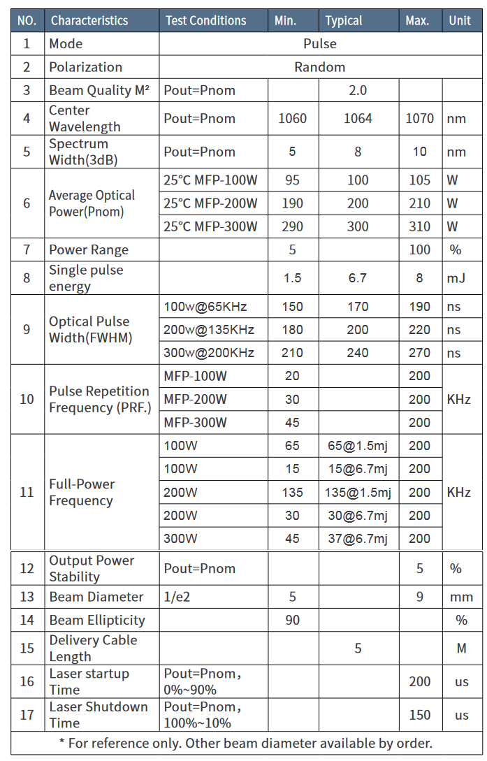
General Characteristic Parameters
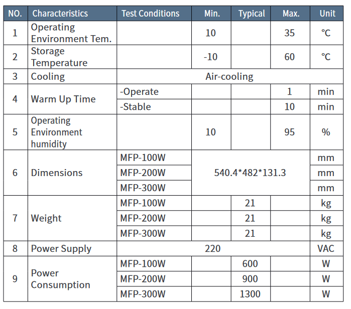
Table 4 Specifications of the 100W Series Pulsed Fiber Laser
| Characteristic\LaserType | 100-M7-M-R | CL-100-1-A | |
| M² | <1.4 | <2 | |
| DeliveryCableLength | m | 3 | 5 |
| AverageOutputPower | W | >100 | |
| MaximumPulseEnergy | mJ | 1.5 | |
| PulseRepetitionRateRange | kHz | 1-4000 | |
| PulseWidth | ns | 2-500 | |
| OutputPowerInstability | % | <5 | |
| CoolingMethod | Air-cooled | ||
| PowerSupplyVoltage (DC) | V | 48 | |
| PowerConsumption | W | <400 | |
| Power supplycurrent requirement | A | >8 | |
| CentralWavelength | nm | 1064 | |
| EmissionBandwidth@3dB | nm | <15 | |
| Polarization | Random | ||
| Anti-ReflectionProtection | Yes | ||
| Built-inRedBeam | Yes | ||
| OutputBeamDiameter | mm | 7.0±0.5 | |
| OutputPowerTuningRange | % | 0~100 | |
| AmbientTemperatureRang | ℃ | 0~40 | |
| StorageTemperatureRange | ℃ | -10~60 | |
| Dimensions | mm | 350*280*112 | |
| PackageSize | mm | 600*450*200 | |
| Weight | Kg | Net:13.2 Gross:14.2 | |
(100-M7-M/L1-R,CL-100-1-A models)
Structural Layout

Laser module dimensions (Unit mm):

The size of the output head of the laser isolator is shown in the figure below (unit: mm)
CAUTION
Average output power should be greater than or equal to 100W, meanwhile the peak power is up to 10kW. Please equip with the optical devices that supports the average power at least 500W or above, and the peak power should be greater than 20kW. Ordinary optical devices which do not meet the standard will result in bad effects.
Operation Guid
Packing List :
| Contents | Quantity |
| User Guide+ Qualified Test Result Power Wire (Optional) | 1 1 |
CAUTION :
If any damage of the external package and internal parts has been found upon receipt of product, please contact Maxphotonics Co., Ltd. or designated agent immediately.
Electrical Power Connection
Power wire

Laser power supply connector:

note:
1, 100W laser mains current needs to be greater than 4A; 2, 200W laser mains current needs to be greater than 6A; 3, 300W laser mains current needs to be greater than 8A.
Control Connector Pin Assignment, DB-25 plug
Pin Function
All control pins are TTL compatible, unless otherwise noted in the pin description. For the interface designs level ranges of the TTL standard should be taken into consideration.
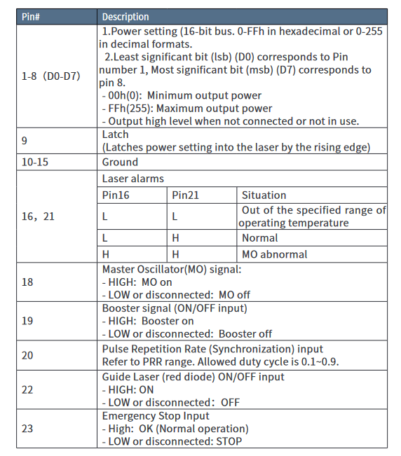

Digital Control Interface (DB-25) Description
- The laser is controlled via signals applied to the DB-25 connector. Please refer to the connector interface description table above for 5.2.1 pin designation and operating levels.
- Pins 1 to 8 are the 8 bit bus for the output power setting. Pin 1 is the least significant bit and pin 8 is the most significant bit. Codes in the range 0…255 (0…FFh) should be applied to these pins, which correspond to the power setting of 0…100% of the specified nominal value, such as:
Set 1 Set 2 Set 3 Set 4 Set 5 Pin 1 Pin 2
0 0
0 0
0 0
0 0
0 0
Pin 3 0 0 0 0 0 Pin 4 0 0 0 0 0 Pin 5 0 0 0 1 1 Pin 6 0 0 1 1 1 Pin 7 0 1 1 1 1 Pin 8 1 1 1 1 1 Current 50% 75% 87.5% 93.75% 100% Laser Power 35% 65% 85% 92% 100% - Pins 16 and 21 are the alarm and status outputs. These pins indicate the following device states:
针 16 针 21 Alarm description L L
L H
Lteamsepretreamtupre raatnugree.is out of the operating Normal Operation H H MO Alarm
- Pin 18 is the Master Oscillator (MO) signal. The MO should be switched ON at least 5ms earlier than the Booster (BS) is switched ON. Once the MO is switched ON, the laser starts to consume more electrical power.
- Pin 19 is the Booster control input. HIGH means switching the BS on and LOW means switching it OFF. The laser starts to emit light within specified delay time after the pin 19 is set HIGH and stops emitting when the pin 19 is set LOW.
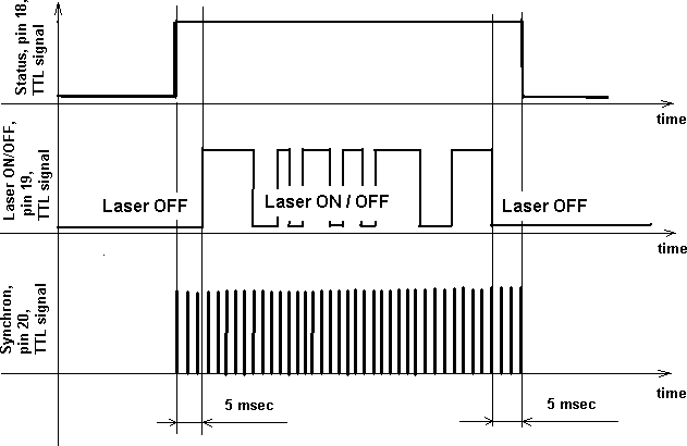

CAUTION :The MO should be switched ON at least 5ms earlier than the BS is switched ON. The laser does not start to emit if you switch the BS ON while the MO is LOW/OFF.If the MO is switched ON later than the BS is switched ON, the laser will emit about 1ms later than the switching of the MO. It is abnormal operation which should be avoid and not listed in the user guide. The BS switches ON simultaneously with the rising edge of the signal applied to the pin 19. - Pin 20 is the Synchronization input. Pulse train with a repetition rate (PRR) within specified operating range should be applied to the pin 20 (refer to the optical specification for PRR limits). The laser emits pulses simultaneously with the rising edge of the signal.
CAUTION:If the PRR is out of the specified range (or no PRR signal is supplied) the laser safety circuit will substitute the missing pulses or limit the PRR.The laser emission is not allowed simultaneously with the guide laser. The BS is blocked internally during the guide laser operation. If pin 19 is set HIGH but the guide laser is on, the laser will not emit light, unless the guide laser is switched OFF. The MO is able to be switched ON or OFF during the guide laser is ON. - Pin 23 is the “Emergency stop” input. It should be set to HIGH for normal operation. In case of dropping this pin to LOW state (even for a short period of time), the laser automatically switches OFF (similar to the state when both MO and BS are OFF). It is necessary to drop both MO and BS to LOW (if they were HIGH) before restarting the laser.
- Digital signal input/output connection

Sketched circuit diagram of input interface

Laser Operation Using Digital Interface
Operation Steps
- Remove the protection cap from the laser output optical head.
- Connect the laser module to the control system via DB-25 connector. Use pins according to the description above. Refer to 5.2.2 Digital Control Interface (DB-25) Description.
- Recommended initial state of control pins:
Pins 18,19 LOWPin 20 With repetition rate within the specified range - Set ” Emergency Stop Input ” (Pin23 ) High
- Set desired power via pin 1-8.
- Switch MO ON applying HIGH to the pin 18.
- Wait 5ms.
- The laser can be fast modulated via Pin 19 and the laser state of ON or OFF can be set with a HIGH or LOW input signal respectively. Switching ON/OFF of the laser has a finite rise/fall time (refer to the specification for the particular model). The time of the modulation should not be less than the sum of rise and fall times, otherwise laser optical response may not be as expected. The typical rise/fall times are 250us, so the modulation period should be greater than 500us (correspond frequency is 2kHz)
- If the next operation time between subsequent ON/OFF batches (jobs) is more than 20ms, it is recommended to switch OFF the MO. This will reduce the power consumption, avoid unnecessary aging of the laser and eliminate the residual MO power at the laser output.
- After finishing the laser operation, switch OFF the BS and MO (set LOW to pin 19 and pin 18).
- Remove all supply voltages.
Operation Features
- PRR can be changed during laser operation with the adjustment of the signal frequency at the pin 20.The time between two adjacent rising edges should be within the specified range of PRR period. It should be less than 50 us when the laser is operated at the minimum PRR of 20 kHz. If the PRR (pin 20) is higher than the upper limit, the laser will be operated at the maximum specified PRR. If the PRR (pin 20) is lower than the minimum allowed PRR, the laser will be operated at the minimum specified PRR.
- The power setting can be changed during the laser operation by applying updated values to pin 1-8 and latching them into the laser via pin 9. The laser will respond to the changes on the subsequent specified rise time.
- If pin 18 is HIGH and pin 19 is LOW, there is laser radiation with the power of less than 20mW.
- If the temperature of the laser module exceeds +45℃ , the laser will be automatically switched OFF and the alarm signal will appears on pins 16 and 21. Even if the temperature drops back to under +45 ℃ , the laser will not resume the emission and keep the alarm pins unchanged until it is re-started.
Common Fault Treatment
Laser Emission Failure
- Make sure the connection of power supply is correct.(+220/110 VAC and GND connect correctly? Earth the ground wire?)
- Make sure the E-STOP switching is released, Emergency Stop Input is high when the laser is in normal operation.
- Make sure the power supply is in normal condition, and check its output without and with load( connected with the laser).
- Software set correctly.
- Interface DB-25 connect correctly under specified guide.
- Normal Signals of Pins 18 and 19.
- Normal signal and supply power of control card(please refer to 5.2 DB-25 control interface pin function).
- Make sure the guide light signal is LOW during marking (Pin22 is “0”). The device’s first priority is to emit the guide light when the guide signal is HIGH.
Power Drops
- Check whether the power supply output steady, and the current is at its rated value.
- For collimated outputs, maintaining a clean output lens is essential, Cleaning with lens tissue is allowable as required. Do not scratched film layer. galvanometer, field lens.
- Inspect whether other optical lens are clean, such as red light combiner,
- Inspect whether optical output is uncovered, isolator output terminal and galvanometer are at grade.
- Normal loss of power from using for 20,000 hours.
- There may be breakage while marking resulted from by signal interference or ground connected incorrectly. The leads of weak and strong current cannot be linked together or at the same side. Use the signal wire with shielded function.
Maintenance Notes
CAUTION ;
- No operator serviceable parts inside. Refer all servicing to qualified Maxphotonics personnel.
- For ensuring that the repairs or replacement within the warranty scope can be carried out, and perfectly maintaining your interests, please submit application to the Maxphotonics or the local representative after finding the faults. Upon receiving our authorization, you need to pack the product in a suitable package and return it.
- You should keep the proof when finding any damage after receiving the product, so as to claim the rights to shippers.
IMPORTANT
Do not send any product to Maxphotonics without RMA.
If the product is beyond the warranty period or the warranty scope, customers shall be responsible for the repairing cost.
CHANGE :
We have the rights to change any design or structure of our product, and the information is subject to change without notice.2 – Service Statements
Service Statements
More problems regarding the safety, set-up, operation or maintenance can be solved by carefully reading this “User Guide”. Please call the Customer Service Department for other questions.
If your problems cannot be solved over the telephone with our technical support group, you may need to return the product to Maxphotonics for further troubleshooting.
Warranty Statemen
General Items
Maxphotonics carries out warranty for any defect of the product caused by its material and production technology within the warranty period agreed in contract, and ensures that its product meet the relevant quality and specification requirements specified in the document under normal use condition.
Maxphotonics rationally determines to repair or replace the products with faults caused by its material or production technology within the warranty period, and repairs or replacement of all the products within the warranty scope are carried out according to the rest of the warranty period of primary products.
Warranty Limitations
Under the following circumstances, the products, parts (including the fiber connectors) or equipment are not within the warranty scope:
- Tampered, opened, detached or reconstructed by personnel outside Maxphotonics;
- Damaged from misuse, neglect or accident;
- Used beyond the specification and technical requirements of the product;
- Indirectly damaged from users’ software or interfaces;
- Improper installation or maintenance, or operating under conditions not included in this manual;
- The fittings and the fiber connectors are not included in the warranty scope.
Customers are obligated to understand the information above and operate according to the User Guide and specification, or the faults arising therefrom are not included in the warranty scope.
IMPORTANT:
Within the warranty scope, purchasers must feedback within 31 days after finding the product defect.
Maxphotonics does not grant any Third Party rights to repair or replace the parts, the equipment or other Maxphotonics products.