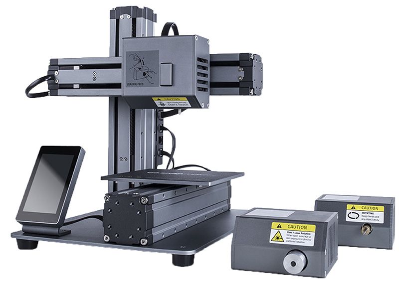
Snapmaker has PWM to control the laser power, but it is inverted, and its amplitude is only 2.5V. The photo below shows the Snapmaker PWM signal, which controls the laser power. 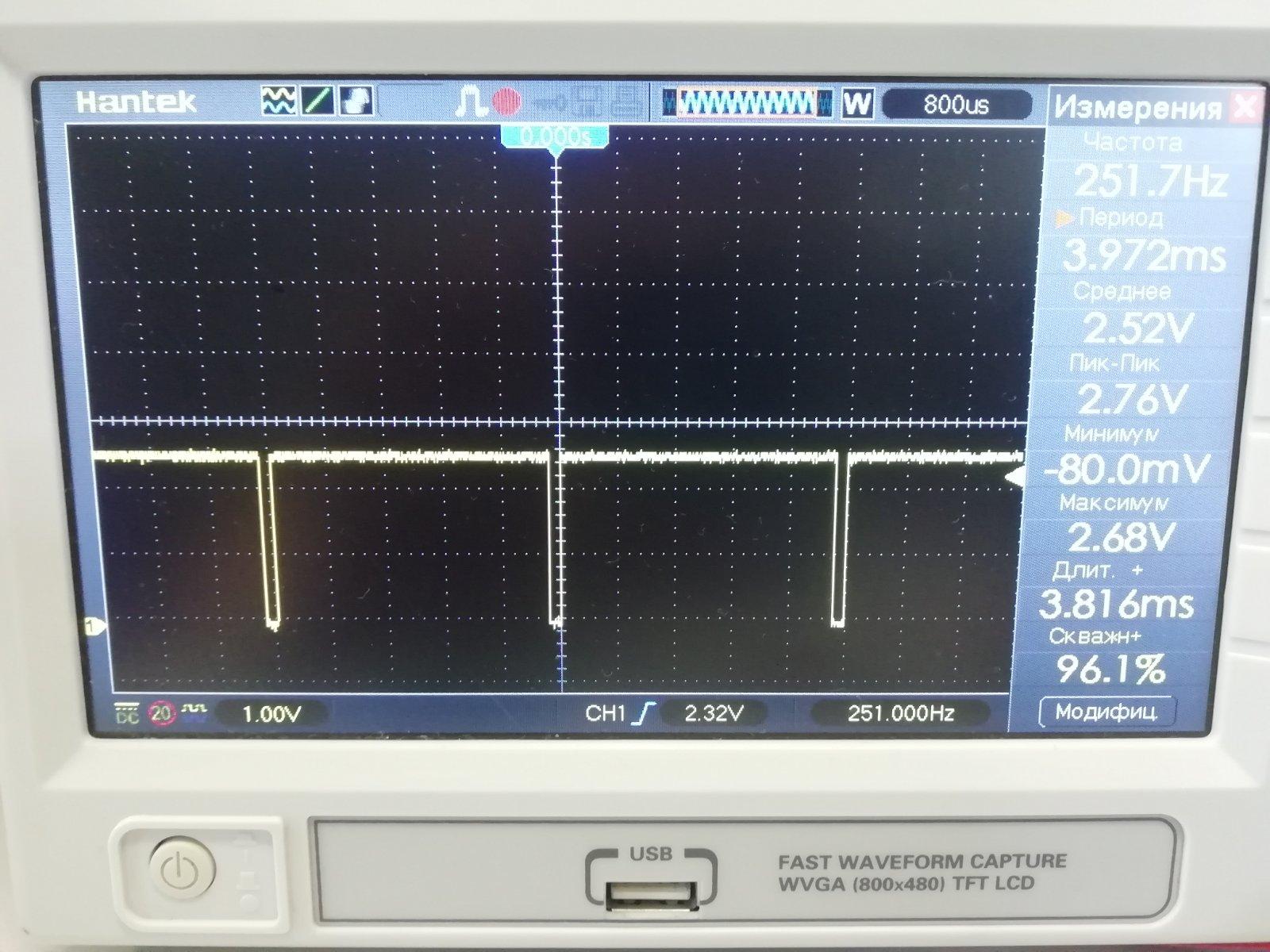
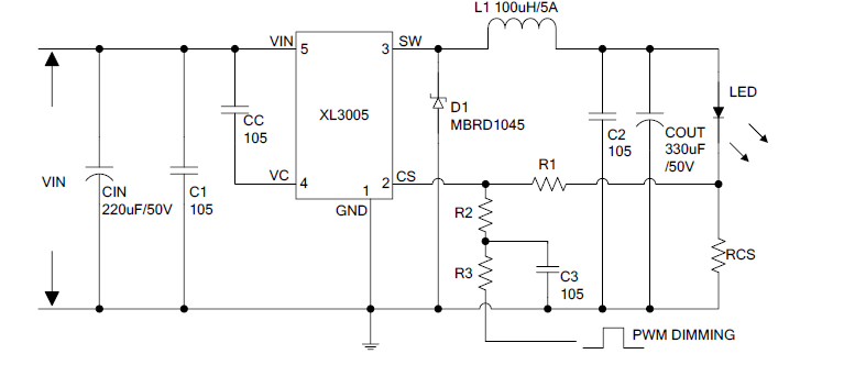
The signal inversion is directly related to XL3005, the laser diode power driver chip that they use.
According to the datasheet for this microcircuit, a positive signal of a certain amplitude (signal from the RCS current sensor) at the CS input of the microcircuit turns off the current increase in the laser diode circuit, thereby limiting the current through it. If an external voltage is “added” to this signal, for example, through a divider, then it is possible to control the operating time of the laser diode and, accordingly, change its power. Therefore, the PWM signal is inverted, +2.5V at the CS input stops the generation of pulses at the SW output of the XL3005 chip.
One more Snapmaker feature is the automatic detection of the modules to be connected to its mainboard The GD32F103 controller located on the laser driver board is in charge of it. 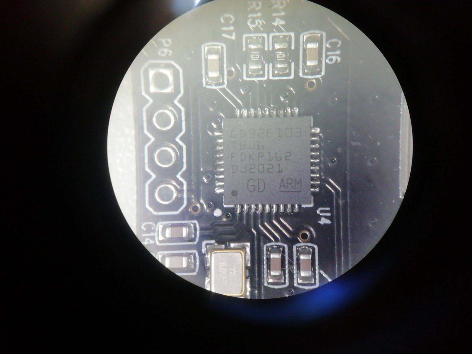
On the laser driver board, you can also find a VP230 3.3-V CAN TRANSCEIVERS microchip. 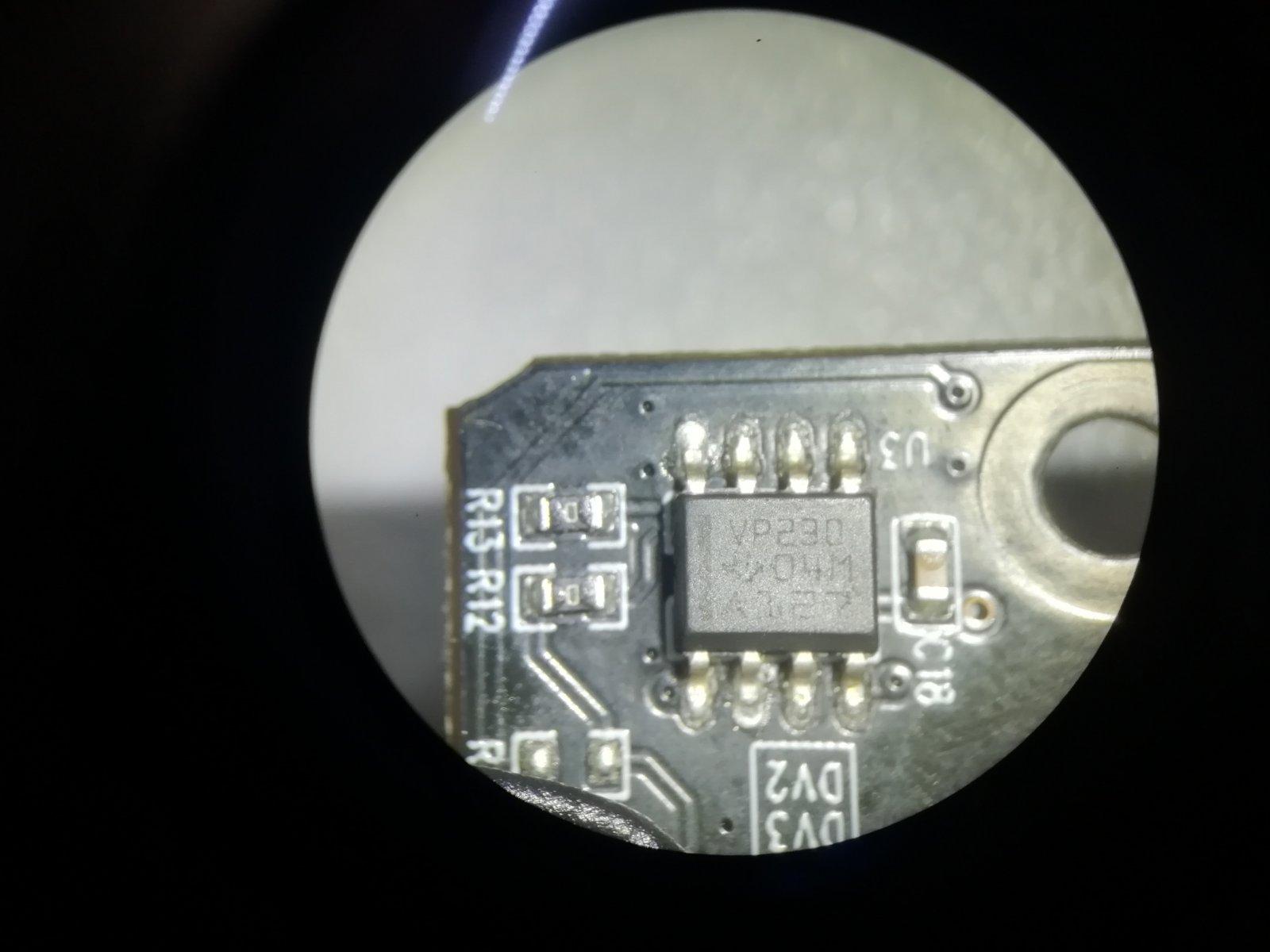
It means that the detection of the connected equipment is implemented via a CAN busbar. And if we don’t connect the original driver board, nothing will happen. The system will not work. That is why we connect the original driver and disconnect the original laser diode from the P2 connector.
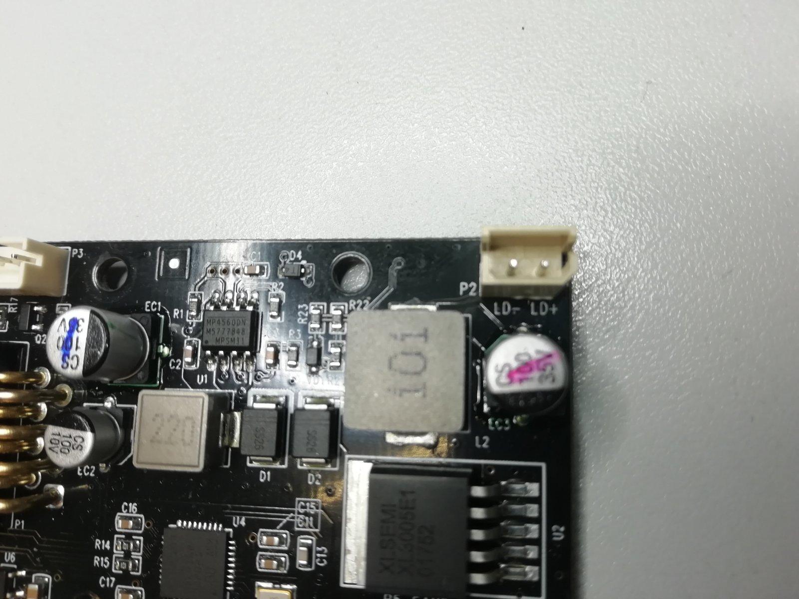
To make our laser work, we need now to invert the Snapmaker PWM signal and increase its amplitude up to 5V. The first waveform is taken on these pins. 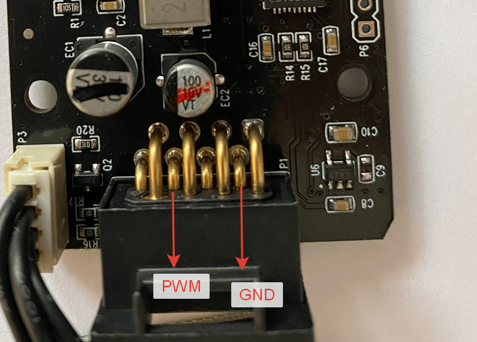
Solder the wires neatly to them as shown in the picture
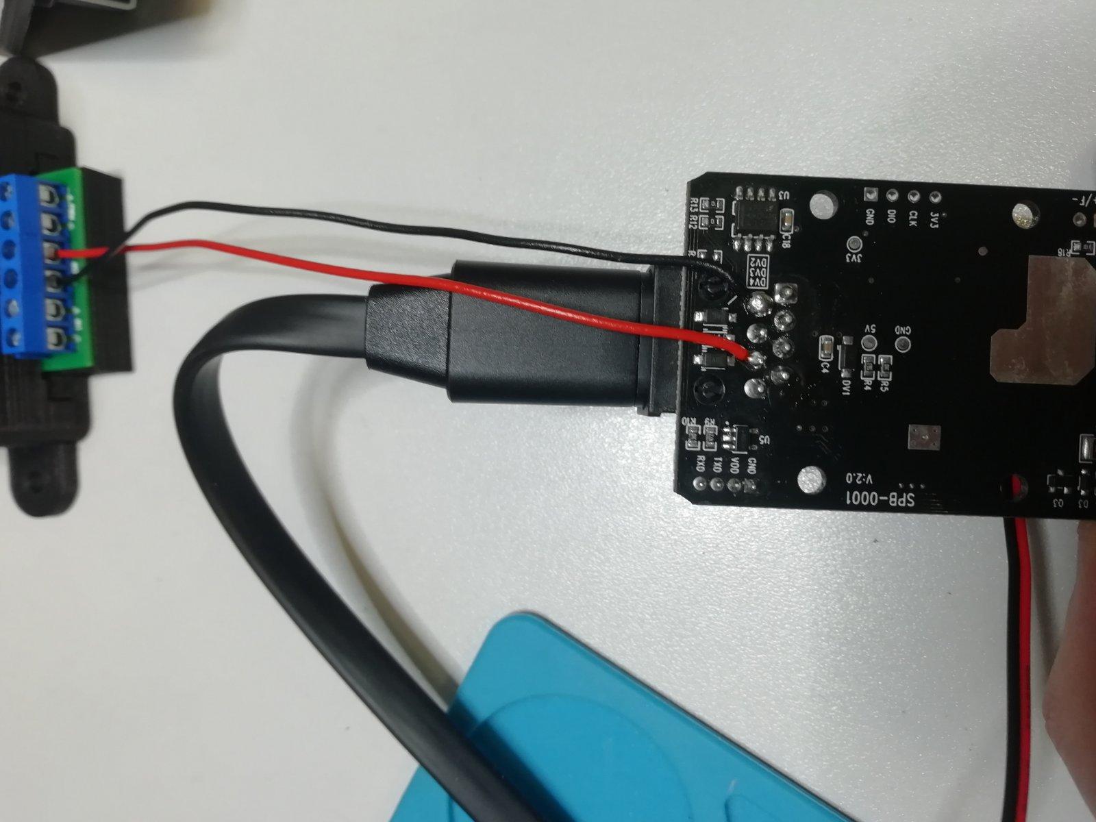
and connect the wires to the IN2 input of the PWM regulator.
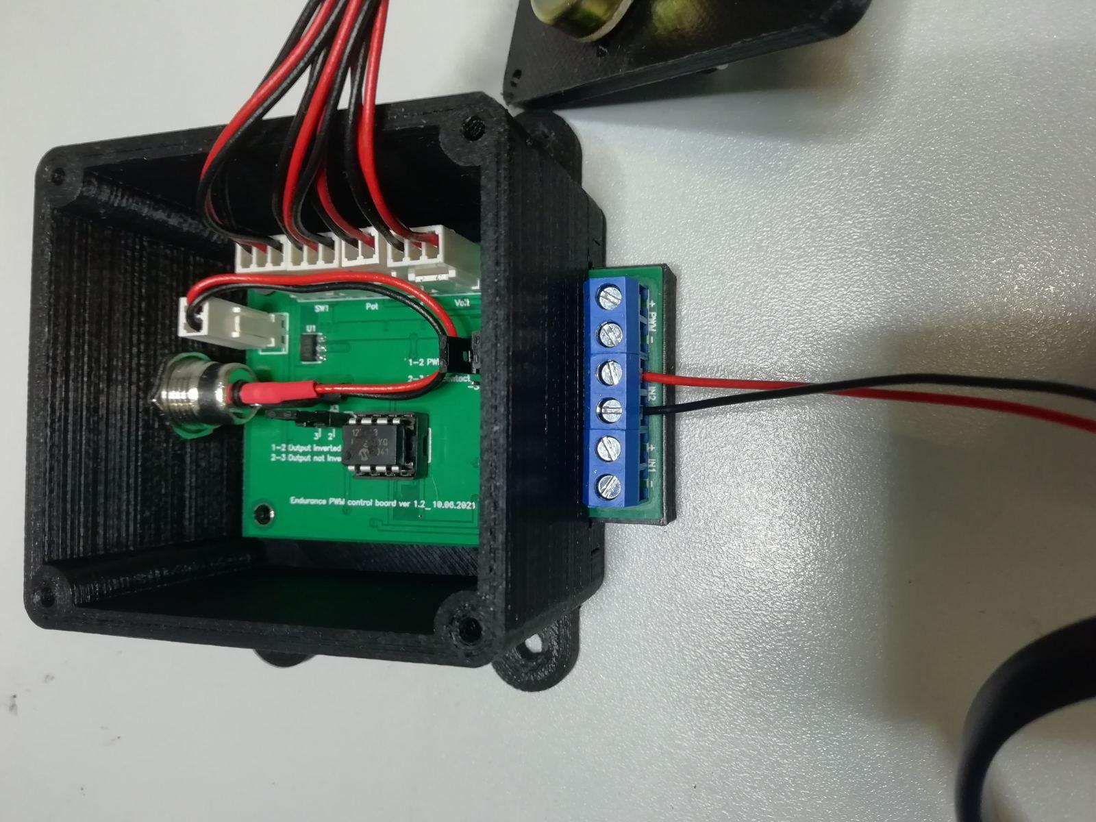
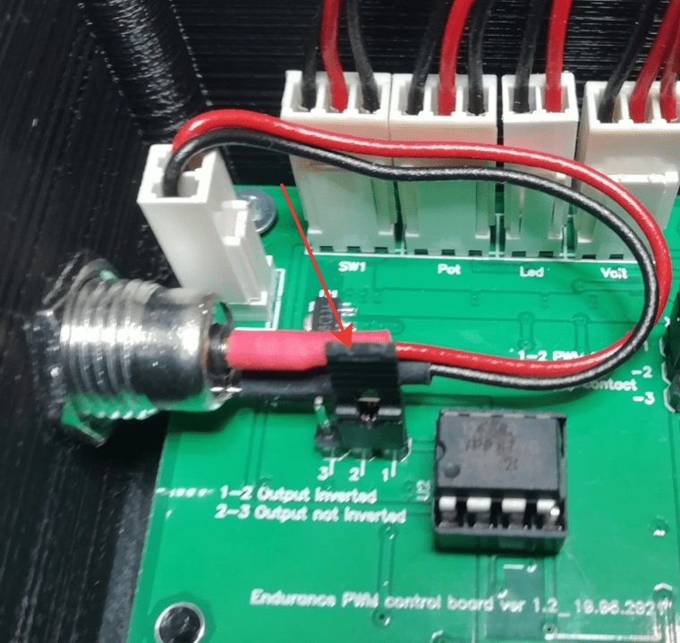
Inside the regulator itself, it is necessary to move the jumper, shown in the picture, to Output Inverted, position 1-2.
Now the signal on the PWM terminals + – of the PWM regulator will look like the in the picture below.
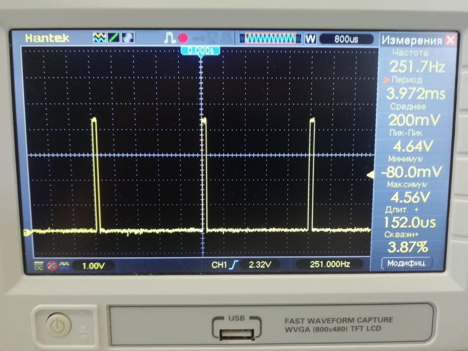
As we see, the PWM signal is inverted with respect to the signal from the Snapmaker controller, and it has an amplitude of 4,6V that makes it possible to connect to it any Endurance laser.
