
MFSC-300W 3D Printing Fiber Laser Series
Contents
Preface
Thank you for using the MFMC Series CW fiber laser from Maxphotonics. We compile this document for you in order that the laser is used and maintained properly. Due to the limited level of the writers, coupled with time constraints, there are some careless mistakes in this document, your understanding and suggestion to help us make an improvement will be much appreciated . Thank you again for using Maxphotonics’ products.
Please take time to read and understand this User’s Guide and familiarize yourself with the operating and maintenance instructions before you use the product. We strongly recommend that the operator read the Section 2 titled “Safety Information” prior to operating the product.
This User’s Guide should stay with the product to provide you and all future users and owners of the product with important operating, safety and other information.
We identify the parts to which you need to pay special attention in the document with underscore. Please notice those information to prevent the unnecessary damages.
MFSC CW 3D Printing Fiber Laser (MFSC 300W) Series products provide a wide range of wavelength from 1060nm to 1100nm. The lasers are air-cooling and maintenance-free and with a wall plug efficiency of more than 25% and deliver high efficiency, high reliability and high performance.
Maxphotonics’ MFSC CW 3D Printing Fiber Laser (MFSC 300W) Series are Class 4 laser products and are designed and tested with safety. By following this User Guide and applying sound laser safety practices, it will be a safe and reliable device.
Laser light exhibits unique characteristics that may pose safety hazards. Therefore, the laser light can’t be normally associated with other light sources, and all operators and people near the laser must be aware of these special hazards.
In order to ensure the safe operation and optimal performance of the product, please follow all warnings and safety instructions in this guide during process of operation, maintenance and service.
For ensuring the safety of operators, operators are urged not to open the equipment privately at all times. There are no user serviceable parts, equipment or assemblies associated with this product. Lasers of unauthorized disassembly shall not be subject to warranty.
Safety Conventions
All safety warning symbols during operating process of the laser include:
WARNING :
Refers to a potential Electrical Hazard to human body. It requires a procedure that, if not correctly followed, may result in bodily harm to you and/or others. Do not proceed beyond the WARNING sign until you completely understand and meet the required conditions.
CAUTION :
Refers to a potential hazard on product. It requires a procedure, that, if not correctly followed, may result in damage to the product or components. In order to ensure normal use of equipment, do not violate the requirement of the CAUTION sign.
General Safety Information
NOTE :
This device is classified as a high power Class IV laser instrument, and the range of wavelength is from 1060nm to 1100nm. This level of light may cause damage to the eye and skin. Despite the radiation being invisible, the beam may cause irreversible damage to the retina. Laser safety eyewear is not provided with this instrument, but must be worn at all times while the laser is operational. Use appropriate laser safety eyewear when operating this device. The manufacturer of the laser system is responsible for the safety compliance according to the applicable standards and regulations.
Laser Protection
Laser Protection Requirements
You must wear the safety protective glasses while operating the laser, and rationally select the safety protective glasses according to the lasing wavelength of the laser. If the device is a tunable laser or Raman product, it emits light over a range of wavelengths and the end user should confirm the laser safety eyewear used protects against light emitted by the device over its entire range of wavelength.
Laser Protective Equipment Suppliers
Maxphotonics recommends material or equipments provided by following laser protective equipment suppliers for you, including LaserVision USA, Kentek Corporation, Rochwell Laser Industries, etc. All the supplier information is provided by Maxphotonics only for the convenience to use, so Maxphotonics assumes no responsibility for any problem caused by using the products of abovementioned suppliers.
Reference Standard
Anti-interference Performance on Electromagnetic Compatibility
- EN 61000-6-4:2007 + A1:2011
- EN 61000-6-2:2005 + AC: 2005
- EN 61000-3-2:2014
- EN 61000-3-3:2013
Power Supply Security
- EN 61010-1:2010
- EN60950-1:2006+A11:2009+A1:2010+A12:2011+A2:2013
Laser Security
- EN 60825-1:2014
- CDRH 21 CFR 1040.10
NOTE:
In accordance with relevant EU and national standards and requirements, the laser must be classified according to its output power and laser wavelength. All MFSC-2000W-4000W-Series laser products with high power belong to Class 4 products (according to article 8, EN 60825-1).
General Safety Instructions
Specular Reflection
There are often numerous secondary laser beams produced at various angles in the output port of the laser. These divergent beams are produced when the primary beam of laser reflects off a smooth surface, and they are called specular
General Safety Information
reflections. Although these secondary beams may be less powerful than the total power emitted from the primary beam, the intensity may be great enough to cause damage to the eyes and skin as well as surface of materials.
WARNING :
You must exercise caution to avoid/minimize specular reflections as these laser radiations are invisible!
Safety Instructions of Accessories
Optical accessories relevant to the laser, such as light-sensitive elements that may be damaged from exposure to the laser light, video cameras, photomultipliers and photodiodes, need related protections.
WARNING :
The Maxphotonics MFSC laser light is strong enough to cut or weld metal, burn skin, clothing and paint. In addition, this light can ignite volatile substances such as alcohol, gasoline, ether and other solvents. During the operating process, the flammable materials around the laser must be isolated.
Optical Operating Instructions
We strongly recommend that you read the following procedures before operating the laser:
- Never look directly into the laser output port when the power is turned on.
- Avoid positioning the laser and all optical output components at eye level.
- Equip with laser beam casing.
- Remove the end-cover before switch ON laser. Or else the output head will be damaged irreversibly.
- Ensure that all personal protective equipment is suitable for the output power and wavelength range of the laser.
- Use the laser in a room with access controlled by door interlocks. Post warning signs. Limit the safety areas to operate the laser.
- Please do not operate laser in darkened environments.
- Do not turn on the laser without an optical coupling fiber or the optical output connector.
- Do not install or detach cutting heads or collimators when laser is active.
- Carry out commissioning, calibration and focusing at low output power and then increase the output power gradually when the calibrating and focusing work is done.
- If the equipment is operated in a manner not specified in this document, the protection devices and performance of the equipment may be impaired and the warranty will be voided.
CAUTION:
- The output of the laser is delivered through a lens with an anti-reflection coating. If the backward-stage light path of your laser has the optical lens, please strictly inspect the lens of the output head and the backward-stage lens of the laser, and ensure that there is no dust and any other impurity on the lens. Please note that any macroscopic attachment may cause extreme damage to lens or burn the laser or any backward-stage light path equipment.
- For cleaning instructions of the lens, please refer to the “Optical Fiber Connector Inspection and Cleaning Guide”.
- Hot or molten pieces of metal may be produced when the laser is under operation. Exercise caution if debris is produced in operation.
- When implement commissioning and calibration of laser output, it’s necessary to set the quality of the spot emitted from the laser at low power levels via an infrared viewer, and then gradually increase the output power.
WARNING :
- Make sure that the individual protective equipment meets the output power and wavelength range of the laser.
- Never look directly into the optical fiber or the collimator, and make sure you wear the safety protective glasses in each operation.
Electrical Operating Instructions
We strongly recommend that you read the following procedures before operating the laser:
- Make sure the shell of this equipment is properly grounded. Any interruption of the ground loop may result in personal injury.
- Make sure the power source connecting equipment is properly grounded.
- In order to further reduce fire hazard, replace the line fuses (if applicable) with the same types and ratings. The use of other fuses or material is prohibited.
- Make sure that the input AC voltage of the laser is the voltage of the normal AC mains, and wires are connected accurately. Any incorrect wiring method may cause damage to people or instrument.
- The equipment does not have any part which can be maintained by operators, and all the maintenance operations must be finished by the professionals of Maxphotonics Co., Ltd.
- To prevent electrical shock, do not remove enclosure, detach the laser without permission and damage the relevant signs.
- Any product with unauthorized dismounting shall not be subject to warranty.
WARNING :
The input voltage of the laser is single-phase AC current (220V AC), which may cause risk of electric shock. All the relevant cables and connection wires have potential hazards.
Environment conditions and precautions
For ensuring the safety of the laser working area, suitable enclosures shall be applied, including but not limited the laser safety signs and the interlocking devices. Corresponding operators must be trained and examined and know the normal safety specifications for operating the laser.
Meanwhile, it is important that the output components shall not be installed at eye level.
Because of interaction of the laser and the metal material, the radiation of high-level ultraviolet light or visible light may be produced. Make sure that the laser is provided with the protective cover to prevent the eyes or other parts of human bodies from damage by radiation.
We recommend that you comply with the following operating measures to prolong the service life of the laser:
- Do not expose the laser to a high moisture/high temperature environment. Install the laser in the cabinet with the function of temperature-humidity control and dust-free.
- Operation at higher temperature will accelerate aging, increase threshold current and lower slop efficiency. If the device is overheated, stop operation and contact Maxphotonics.
CAUTION :
- Exercise caution to avoid damage to the device.
- If the laser will be in an environment of less than 0 degrees Celsius, drain all coolant out of laser completely to prevent damage to the laser.
Product Description
Property Introductions
As high power lasers developed for industrial application, MFSC Series lasers are compact and efficient. The lasers are mainly applied to the fields of welding, cutting, brazing, etc.
Main Features:
- High-quality laser output
- High power, high efficiency
- High reliability, long service life
- Compact, rugged package
- Extension programming interface
Applications:
- Industrial applications
- Scientific research
Module Configuration
Maxphotonics offers many configurable modes. This manual will give complete instructions for all modes, please refer to section 6.3-6.6.
Model Coding Rules
| Model | Model Coding Rules |
| MFSC-300W | Maxphotonics Single-mode CW 3D Printing Fiber Laser 300W |
Certification
Maxphotonics certifies that this equipment has been thoroughly tested and inspected and meets published specifications prior to shipping. Upon receiving your equipment, check whether the packaging and accessories have been damaged in transit. If damage is apparent, please contact Maxphotonics immediately.
Front Panel Description
Front Panel Description

Emergency stop switch
| ITEMS | FUNCTION DESCRIPTION |
| (OFF ON) Key Switch | Power switch of laser |
| (Emergency stop) Emergency Stop Switch | Emergency stop |
| (Start) Start Switch | Start laser (on-off signal of hardware) |
| ALARM | Abnormal situation light of laser |
| ACTIVE | Normal situation light of laser |
| POWER | Power light of laser |
Back Panel Description

| ITEMS | FUNCTION DESCRIPTION |
| CTRL | External control connector |
| RS232 | RS232 connector |
| AC220 | 220VAC power input |
| POWER | Leakage protection switch |
| OPTICAL OUTPUT | Output Connector |
Optical Output Terminal
Optical Output Head
The optical output head come with a protective window that can be replaced if damaged. Please refer to Chapter 7 about the cleaning method.
Make sure that the black end cap of the QBH/QCS head is removed prior to use and is usually arranged with the laser.
Optical Output Head (QBH head)

Fiber output head (QCS head)

Specification
Optical Characteristic Parameters
| No. | Characteristics | Test conditions | Min. | Nom. | Max. | Unit |
| 1 | Operation mode | CW/Modulated | ||||
| 2 | Polarization | Random | ||||
| 3 | Nominal Output power (MFSC-300W ) | 100% CW | 285 | 300 | 320 | W |
| 4 | Tuning range of output power | 10 | 100 | % | ||
| 5 | Emission wavelength | 100% CW | 1070 | 1080 | 1090 | nm |
| 6 | Spectrum width(3dB) | 100% CW | 3 | 4 | nm | |
| 7 | Short-term power instability | 100% CW>1h | 1 | 3 | % | |
| 8 | Long-term power instability | 100% CW>24h | 3 | 5 | % | |
| 9 | Beam quality M² | 100% CW | 1.1 | 1.2 | ||
| 10 | Laser switching ON time | 10%→90%Output | 3 | 5 | μs | |
| 11 | Laser switching OFF time | 90%→10%Output | 3 | 5 | μs | |
| 12 | Modulation rate | 100%Output | 20 | 50 | KHz | |
| 13 | Red guide laser power | 100%Output | 150 | μW | ||
| 14 | Feeding fiber cable length | ( | 2 、 、 | m | ||
| 15 | Feeding fiber core size | 20 25 30 50 optional) | μm | |||
| 16 | Feeding fiber cable bending radius | 200 | mm | |||
| 17 | Output form | Standard QCS/QBH(LOC) | ||||
General Characteristic Parameters
| No. | Characteristics | Test conditions | Min. | Nom. | Max. | Unit |
| 1 | Operating voltage | 180 | 220 | 240 | VAC | |
| 2 | Normal power consumption(MFSC- 300W) | 100%Output | 1.5 | KW | ||
| 3 | Operating ambient temperature range | 0 | 35 | ℃ | ||
| 4 | Operating ambient relative humidity | 10 | 90 | % | ||
| 5 | Cooling method | Air-cooling | ||||
| 6 | Storage tem. | -10 | 60 | ℃ | ||
| 7 | Dimensions | 482×610.4×139.3 | mm | |||
| 8 | Weight | 26 | kg | |||
Structural Layout
Laser Three Views.(Unit:mm)

Table 4 Specifications of the 100W Series Pulsed Fiber Laser
| Characteristic\LaserType | 100-M7-M-R | CL-100-1-A | |
| M² | <1.4 | <2 | |
| DeliveryCableLength | m | 3 | 5 |
| AverageOutputPower | W | >100 | |
| MaximumPulseEnergy | mJ | 1.5 | |
| PulseRepetitionRateRange | kHz | 1-4000 | |
| PulseWidth | ns | 2-500 | |
| OutputPowerInstability | % | <5 | |
| CoolingMethod | Air-cooled | ||
| PowerSupplyVoltage (DC) | V | 48 | |
| PowerConsumption | W | <400 | |
| Power supplycurrent requirement | A | >8 | |
| CentralWavelength | nm | 1064 | |
| EmissionBandwidth@3dB | nm | <15 | |
| Polarization | Random | ||
| Anti-ReflectionProtection | Yes | ||
| Built-inRedBeam | Yes | ||
| OutputBeamDiameter | mm | 7.0±0.5 | |
| OutputPowerTuningRange | % | 0~100 | |
| AmbientTemperatureRang | ℃ | 0~40 | |
| StorageTemperatureRange | ℃ | -10~60 | |
| Dimensions | mm | 350*280*112 | |
| PackageSize | mm | 600*450*200 | |
| Weight | Kg | Net:13.2 Gross:14.2 | |
(100-M7-M/L1-R,CL-100-1-A models)
Disassembly Step
laser belongs to the precise valuables, so Maxphotonics recommends the following steps to unpack the packing box.
Please unpack according to the following steps:
- Place the packing box containing the laser on a horizontal platform such
as the floor or a large table.
- Open the primary box and remove the foam cover.
- Since there is fiber on top of the laser, please carefully take it out from the
box and ensure that the maximum bending radius of the optical armoured cable is greater than 400mm. The fiber shall be taken out under cooperation of three employees, with two employees lifting the main body of the laser and another employee taking out the armoured cable.
- Remove the form cover and take out the fittings.
- Check the fittings according to the ”Packing List”.
- Keep all objects after unpacking for future transportation or storage needs
CAUTION :
- If any damage of the external package and internal parts has been found upon receipt of product, please contact Maxphotonics Co., Ltd. or designated agent immediately.
Packing List
| Names of fittings | Description | Unit | Quantity |
| Fiber Laser | MFSC-300W 3D Printing | piece | 1 |
| 220VAC power wire | 4M | piece | 1 |
| External signal wire | 3M | piece | 1 |
| USB Transfer RS232 signal wire | UNITEK:Y-108 | piece | 1 |
| Power Keys | piece | 1 | |
| USB disk | 16 G | piece | 1 |
| Lens cleaning paper | piece | 4 |
Operation Guide
Notice
Caution :
- Please refer to Section “Detail Specification Table” for proper electrical power.
- Refer to Section “General Safety Instructions” for inspecting whether the configuration environment of peripheral work of the laser meets the requirements.
Electrical Power Connection
A power input cord of the laser shall be connected to single-phase AC current. Please make sure the grounding cord is perfectly connected, or the laser may be damaged potentially.
For ensuring the safety feature, Maxphotonics recommends you connect a 20A circuit breaker (air switch) in series between the power supply unit and the laser. This electric power shall be in close proximity to the power supply unit of the equipment and can be easily disconnected.
Refer to Section “Detail Specification Table” to determine your electrical specification if you have any problem about wiring.
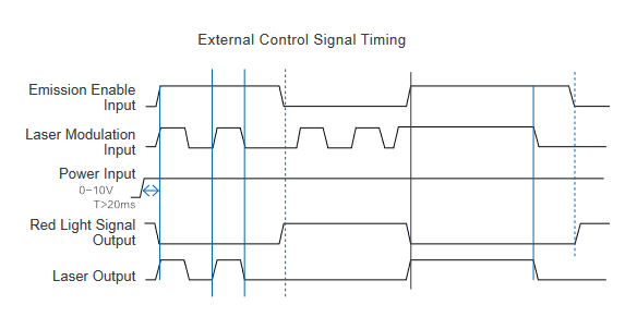
Extension Interface

For ensuring the communication between the laser and the board card, Maxphotonics adopts the high-quality HARTING terminal and provides the CTRL interface connectors. The interface definition is shown in the figure below.
CTRL Interface Definition
| CTRL | WIRE COLOR | FUNCTION | REMARK |
| INTERFACE PIN | DESCRIPTION | ||
| 1 | Brown and white | Fault output 2 | Alarm fault output 1 |
| and 2 normally closed | |||
| 14 | brown | Fault output 1 | No alarm fault output 1 |
| and 2 normally open | |||
| 2 | Green and white | DA (0-10V) input – | 0~10V analog signal, |
| 15 | green | DA (0-10V) input + | control output power% |
| 3 | Black yellow | External light – | 24VDC active high |
| (this function is | |||
| 16 | yellow | External light + | the same as the |
| start switch START | |||
| function) | |||
| 4 | Black and white | Modulation input – | 24VDC active high |
| 17 | black | Modulation input + | |
| 5 | Red and white | Enable input – | 24VDC active high |
| 18 | red | Enable input + | |
| 6 | Light blue black | External emergency stop control – | No need to connect |
| 19 | Light blue | External emergency stop control + | No need to connect |
| 7 | Orange black | Interlock + | No need to connect |
| 20 | Orange | Interlocking – | No need to connect |
Fiber Connector Inspection and Cleaning Guide
Tools
For cleaning a fiber connector you need the following materials:
- Powder-free rubber gloves or fingerstall
- Lint free optical cleaning wipes and/or swabs
- Ahydrous ethanol(Optical level, pure >99.5%)
- Compressed air (oil free, water free)
- Microscope
- Light source
Operation Guide
CAUTION:
- It is imperative that the protective lens are checked for dirt, dust, or damage before you use the fiber connector. It will lead to heavy damage if the laser equipped with dirty or damaged fiber connector.
- The use of dirty fiber connectors can result in laser damage, which is not covered by the Maxphotonics’ warranty.
- The laser will not be covered by the Maxphotonics’ warranty if change the laser personally.
IMPORTANT :
- It is imperative that you wear powder-free rubber gloves during this cleaning procedure! It is hereby stated that damage to the fiber connector can occur due to mishandling, the use of incorrect cleaning procedures, or chemicals for cleaning. This is not covered by the Maxphotonics’ warranty.
- Ethanol concentration should be above 99.5% during cleaning.
Operating Procedures
Cleaning and maintaining according to the following procedures:
- Switch off the laser power, and place the key switch on position of ”OFF”;
- Remove the black outer protective sleeve and leave the white inner cap on and clean the fiber connector exterior with optical cleaner, wipe it with a clean optical wipe and dry it with compressed air.
- Place fiber connector in the holder of the microscope, remove the white inner cap from the connector.
- Focus the microscope onto the connector surface so that the protective lens can be seen clearly from the microscope.
- Check the surface carefully. If some contamination is visible on the surface, cleaning is necessary:
Put a few drops of alcohol onto the lint free swabs and throw away the excessive alcohol.Place the swabs on the dust via microscope.Cleaning the dust carefully, and move it to the edge of lens.
Repeat these cleaning steps until all contamination is removed. Take a final check under the microscopy.
- Reinstall the inner cap and the outer sleeve onto the cleaned fiber connector.
- Take out the cap and sleeve, then connect the fiber connector with cutting head quickly and fasten them. (Place the cap face down on a clean surface or a lint-free wipe.)
Take out the cap and sleeve

Mounting the fiber optic connector on the microscope

Cotton swabs to protect the lens

IMPORTANT :
- Do not reuse a lint-free optical wipe or swab.
- Do not touch the protective lens of the fiber connector.
- Do not blow directly, or else new dirty will be brought.
- Do not touch the tip of the cleaning swab with your fingers and use each swab only once.
- Cleaning is necessary before place the protect cover and sleeve.
- Never blow air directly at the surface , because you could imbed contaminants into the surface. Always blow across the surface !
- If the fiber connector could not be installed in optical system immediately, please cover it with the protective cap cleaned with compressed air.
Start Step
WARNING :
- Make sure that all the electrical connections (including cooling water connections) are connected prior to use. All the connectors must be held steady with screws if possible.
- NEVER look directly into the output fiber and make sure that you wear the laser safety eyewear while operating the product.
- Make sure all power is removed from the laser when wiring.
Starting procedures are as follows:
- Remove the end cap of the collimator;
- Make sure that the end surface of the collimator is clean and not covered with impurities;
- Make sure that the emergency stop switch is turned on;
- Open the power supply of the laser;
- Place the key switch of the front panel on position “ON”.
- Press the START button on the front panel. (For external control method)
Mode Description
The working modes of the laser are as follows:
- Internal control: Control the output of the laser via control software. This mode is used for checking whether the laser is normal or not, and testing the laser power.
- External Control: control the output of the laser via external control line (Enable, Modulation, 0-10V analog voltage and START button). The mode is used for cutting and welding.
Software Description
- The installer is stored in a randomly packed U disk.
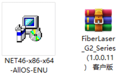

- Double-click the “NET46-x86-x64-AllOS-ENU.exe” file to install the .NET runtime environment.
- Right click to extract the “FiberLaser_G2_Series(1.0.0.11) client version.rar” compressed file to the root directory of the D drive.
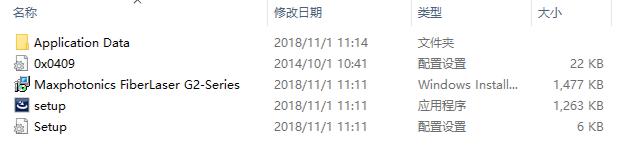

- Double-click the “setup.exe” file to install the laser application software. After the installation is complete, a shortcut will appear on the desktop.
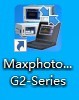

- Double-click the shortcut, the program starts running, enter the connection interface.
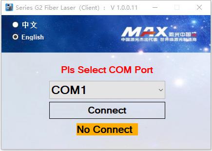

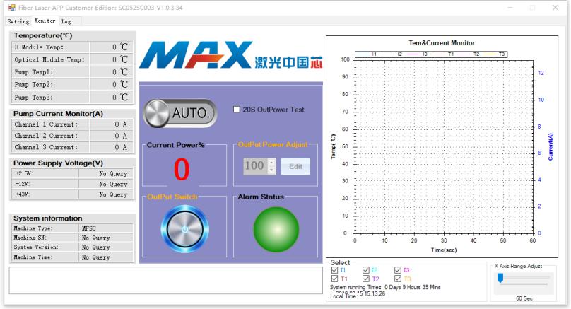
- Use the random serial port cable to connect the laser to the PC, select the port number, click to connect the laser, and enter the following monitoring interface.


Error List
The fault alarm points set by the laser include:
| No. | Message | Description | Trouble shooting |
| 1 | PD alarm | Laser internal light path testing fault | Operation leads to low output power of laser such as low modulation frequency, low peak power, low cutting power. |
| 2 | Water flow warning of the chiller | The chiller is not started or water flow is not sufficient | Start the chiller and make sure that there is sufficient water flow in the water line. |
| 3 | Overheat alarm | Overheat fault of the laser | For the internal overheat fault of the laser, please check whether the pre- set temperature of the chiller meets the requirements. Shut down the laser and do not restart it until the heat accumulated during operation dissipates thoroughly. |
| 4 | Overcurrent alarm | Overcurrent fault of the laser | If ”0-10V” DA value exceeds the pre- set value, the internal overcurrent fault will occur. |
| 5 | QBH installation alarm | Install error of the QBH | The fault will be produced when QBH head is not inserted into the cutting head or at the wrong place. |
| 6 | Emergency stop alarm | The emergency stop switch is pressed | Release the emergency stop switch, the laser will work again after being restarted. |
| 7 | Communication error of RS232 | Communication error between the laser and the PC | Check the RS232 interface and cable of the computer. |