LED Clock – getting started!
Browsing through Youtube, I noticed some interesting clocks manufactured with LED displays, some with 3D printed bodies, many using programmable LED’s, controlled by an Arduino.
As I have made a few items with Arduino as a controller, thought a clock would be good for my workshop, which is actually the study at home.
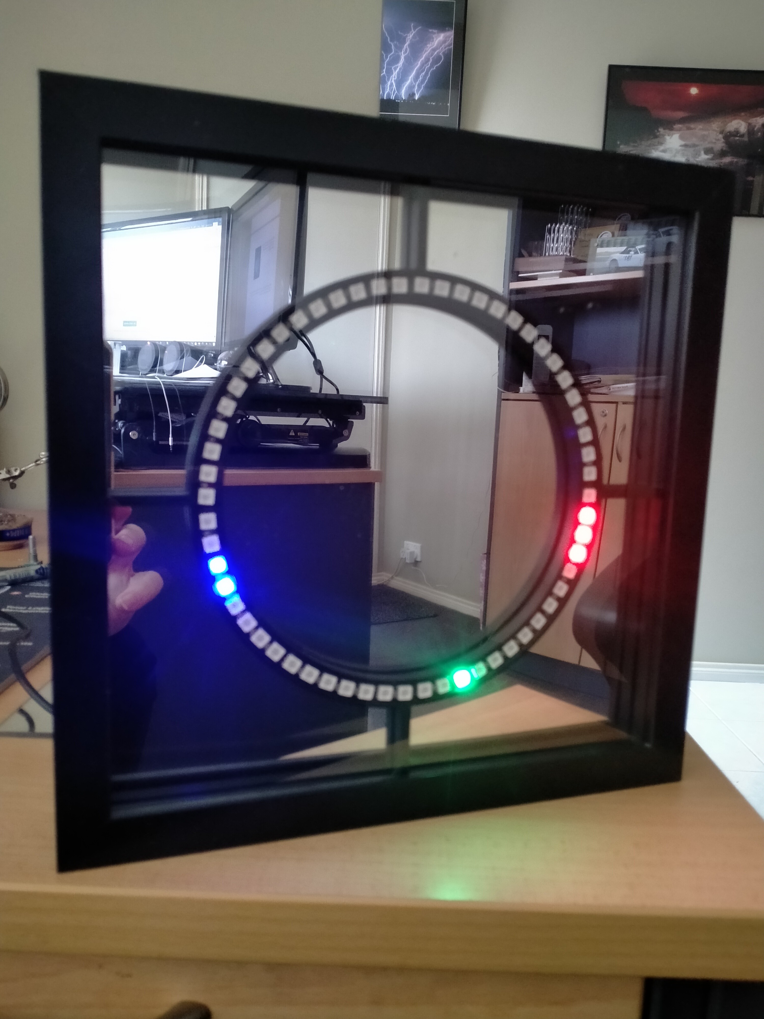
I decided to make a unit, using an off-the-shelf picture frame, programmable LED’s, a real-time clock, and the Arduino UNO. You could also use an Arduino Nano as well if you want to keep things small. The plastic mount for the LEDs I designed and made on the 3D printer. I needed a spacer inside the frame, so printed that as well.
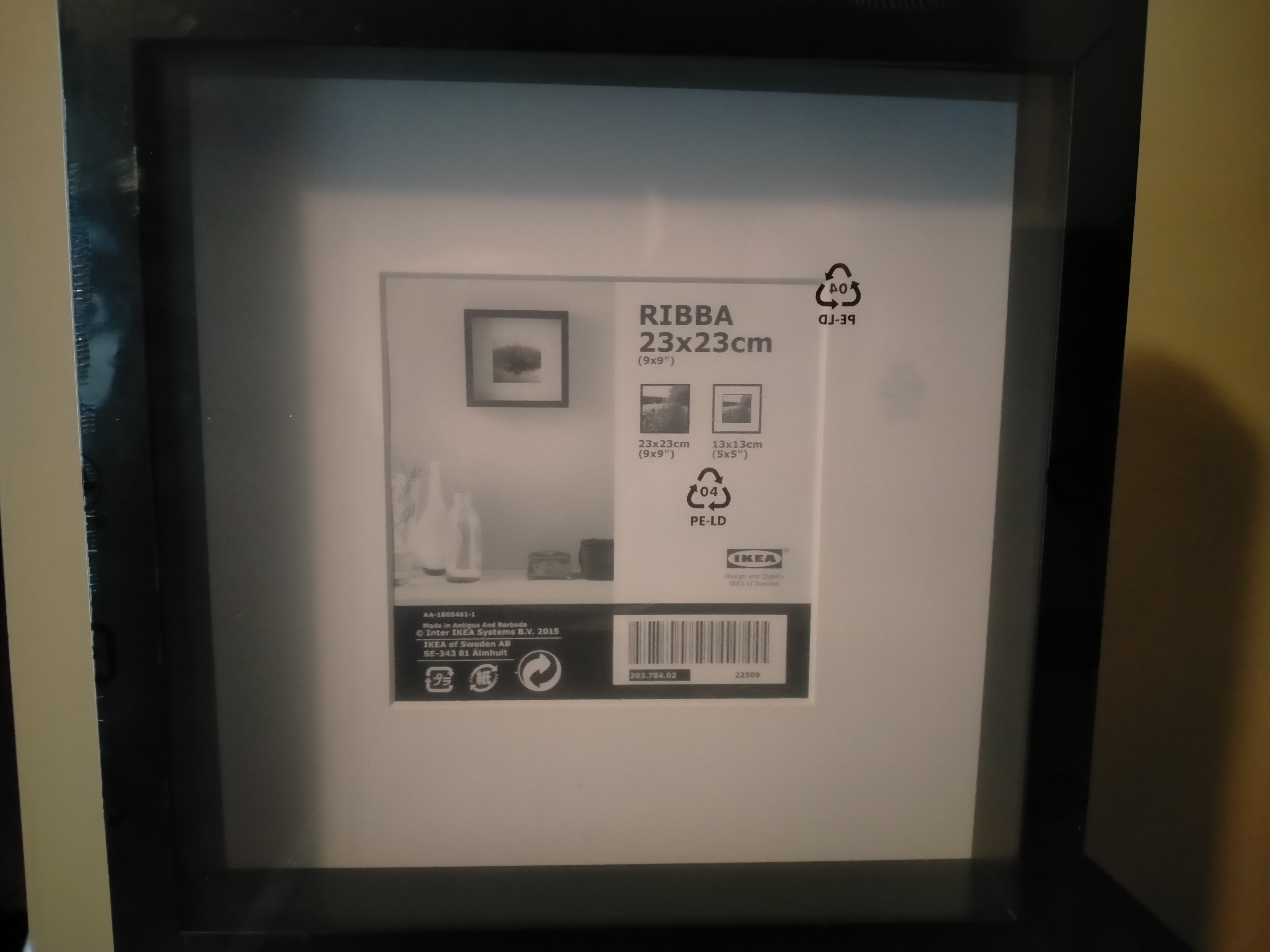
The picture frame came from IKEA. It is a RIBBA, 230mm x 230mm, and is approx. 45mm deep. The clear plastic in the front is very thin, but for what I wanted, it is fine. I used a piece of 3mm mirrored Acrylic behind the LED framework.
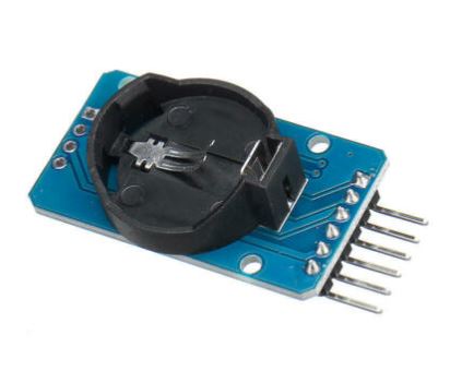
There are a few real-time clocks available for the Arduino, and after doing a little research, went for a DS3231, which seemed to be the best of the bunch. Time is kept using a CR3203 battery, which is good for a year or more.
The LEDs are available in rings, having various quantities of LEDs already attached to the printed circuit boards. There is one with 60 lights, perfect for a clock. It comes in 4 sections and is easy to solder together.
The remaining items required are an Arduino UNO, or Nano, a prototype PCB to mount the electronics, and a rotary encoder to enable the clock to be set, and change some of the functions.
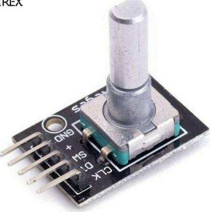
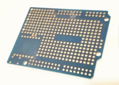
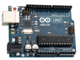
Arduino UNO PCB Rotary encoder
After assembling the 4 LED sections, I used Design Spark Mechanical to design the LED mount, and the necessary spacer required. These drawings were then exported to Cura to create the G-codes for the 3D printer.
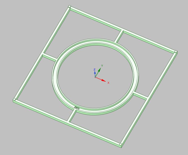
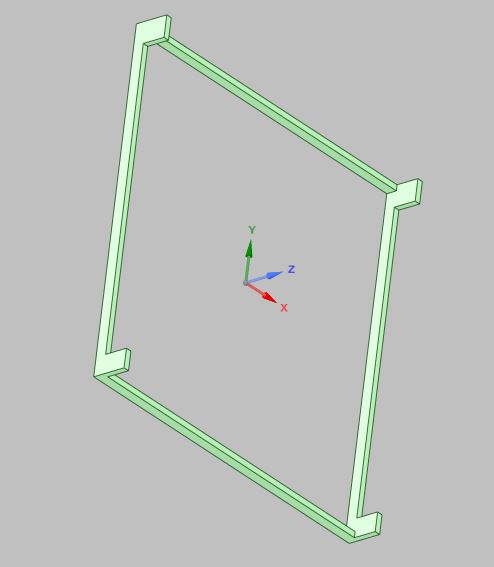
LED housing DWG Spacer DWG
Programming and assembly were not too difficult. All the electronic components were soldered to the PCB, and wiring for the LED and rotary encoder was attached as well. The Led’s do require a capacitor on the power wires, and a resistor on the data wire to the lights. I am not an electronics engineer, but simply followed the instructions for the lights. They are required to stop the 1st LED from failing, and also stop any spikes along the data wire.
A big thanks must go to a Youtuber called Cine-lights. They make many interesting items using programmable LED’s, a clock being one of them. They make all the instructions and coding required available to anyone who wants it.
I am able to do simple programs for the Arduino, but a clock is a bit above my pay grade, so I used their code.
The clock requires 5 volt input to run the lights, and this means it can be powered via any standard USB outlet, or a USB power bank, as the current draw is fairly low, as there are only 6 LED’s on at any one time, depending on what clock face you want to use. I used a 5volt 2 amp plug pack to power the lights, and the Arduino as well.
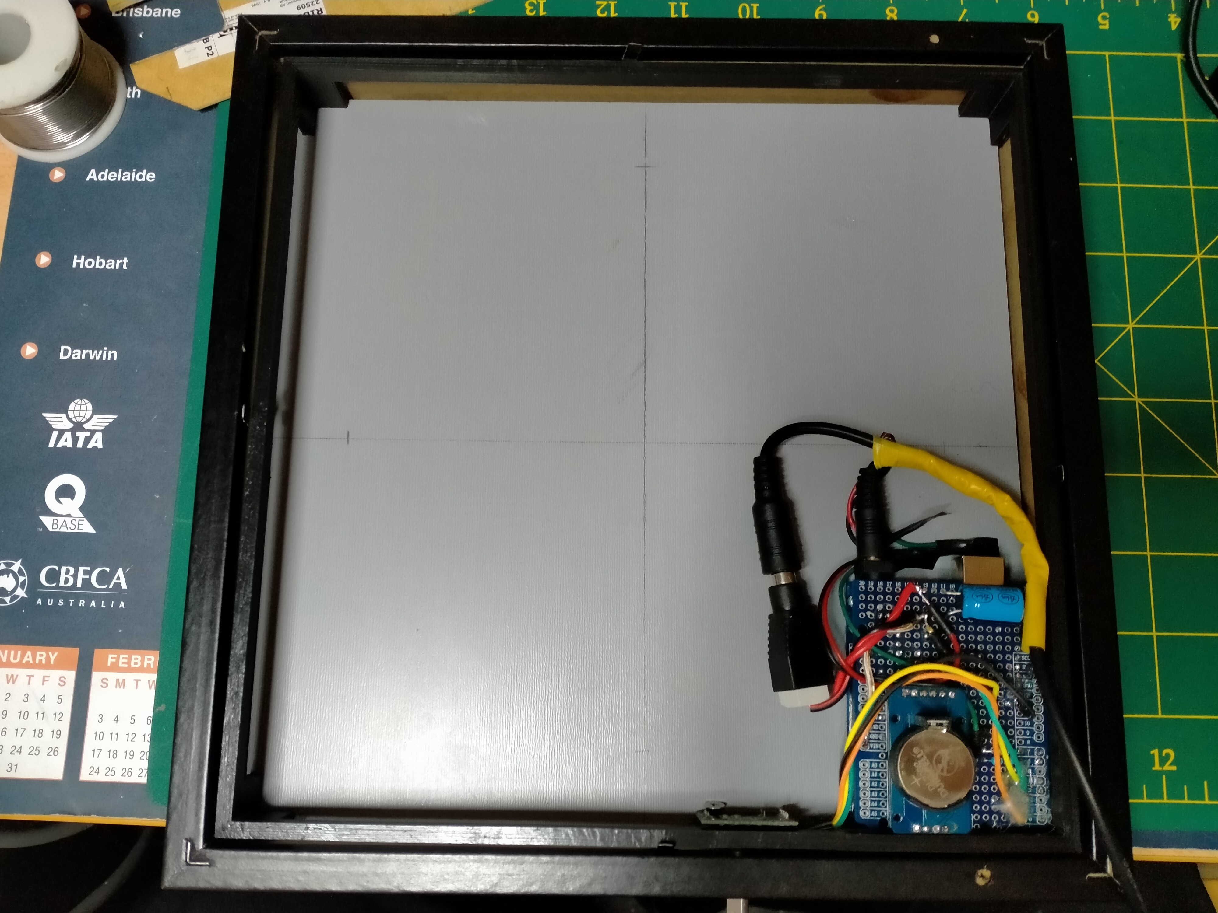
The rear of the frame with electronics in place. 3D printed spacer fitted as well.
The clock has been running for about a year now, still on the 1st CR2032 battery, and keeps good time.
Do not have to reset the clock every time it is turned off. 5volts is just for the lights, and the CR2032 handles the real-time clock.
After recently getting a desktop engraver, which came with a 2.0-2.5-watt laser as well, I did a little redesign and made a new clockface using Red and White 210gsm card stock, and burning in numbers, as well as cutting slots in the White material, allowing the Red to show through from behind. Also did a pattern in the 4 corners surrounding the clock face on the Red. It is a bit hard to see the pattern, so might do it again and infill some of the areas to make it show up better.
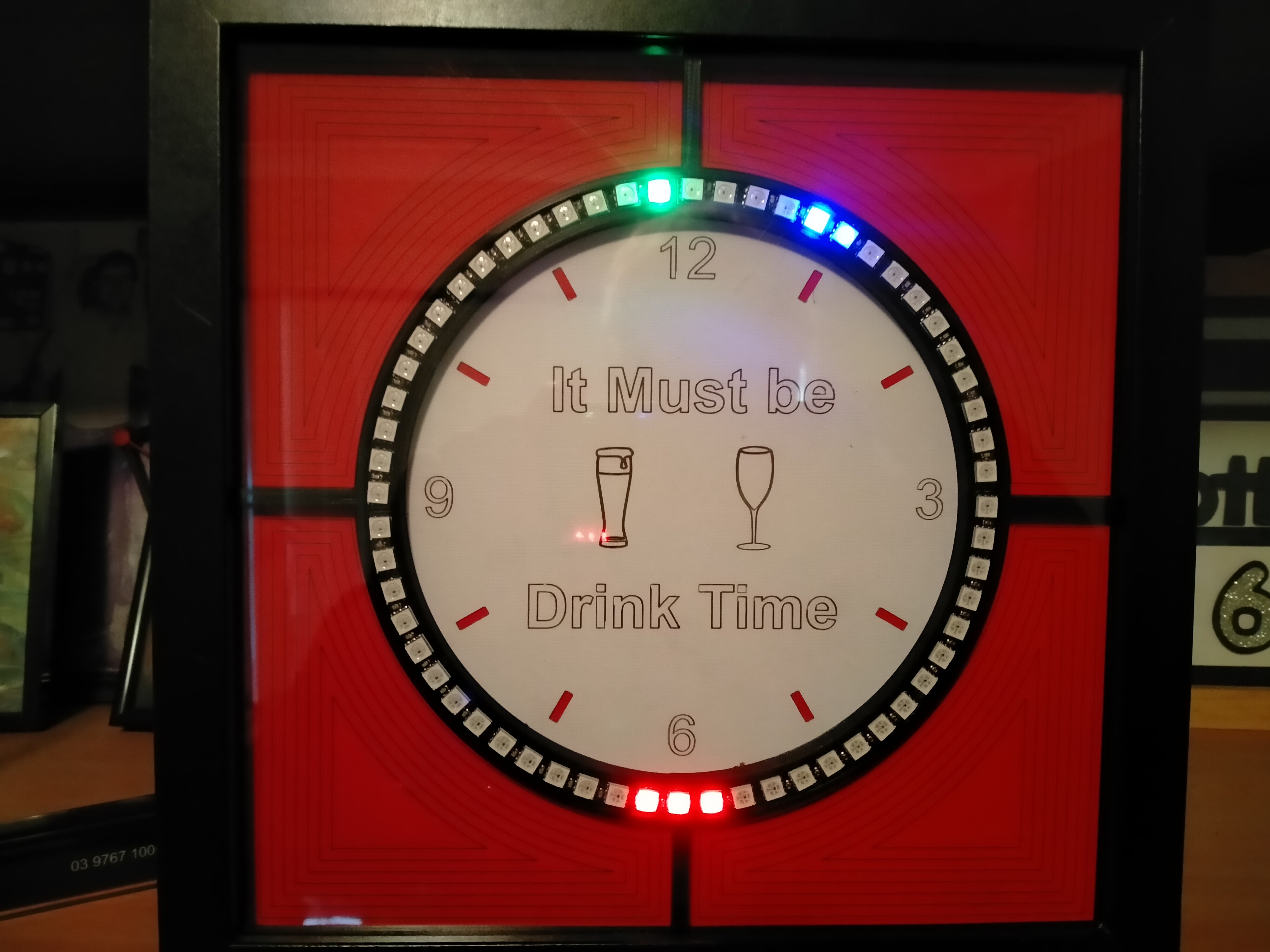
3 Red LEDs are for the hours, the Green one is for the minutes and the Blue is for the second hand.
Suggest you check out Cine-Lights on the link shown above, which shows all the available settings.
I Will possibly do another one with some sort of timber face, and either engrave numbers or use the Laser again to burn them in.