Endurance lasers present a universal laser pulse detector.
A Detector of Laser Pulses for a Wavelength of 400-1100 nm
The general mode of operation
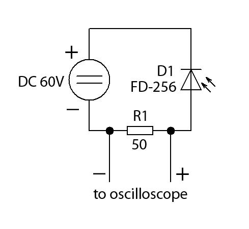
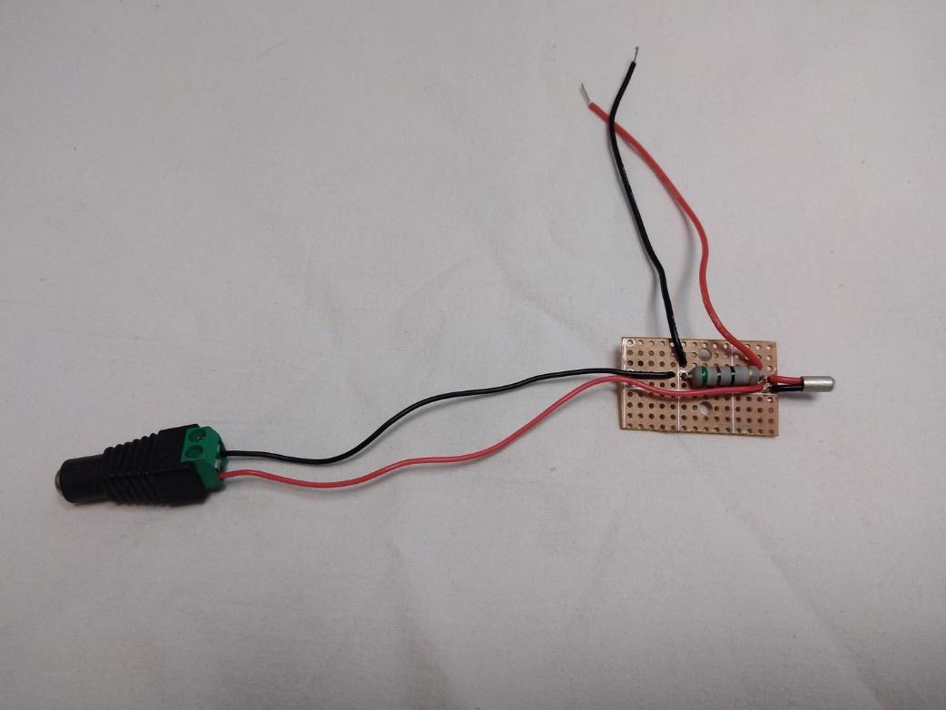
The pulse detector is based on a photodiode incorporated according to a photodiode circuit with a load resistor and an inverse power supply voltage polarity.
When a light signal hits a photodiode, charge carriers are generated inside it. Their quantity is proportional to the light signal power. These carriers are caught by the electric field created by the voltage applied to the photodiode, and an electrical current proportional to the light signal power is generated in the circuit. By measuring the load resistor voltage with an oscilloscope, it is possible to measure the shape and duration of the light signal pulses. To measure pulses the photodiode and oscilloscope time resolution should be several times less (preferably, by an order) than the duration of the measured pulses.
In our detector, we use a photodiode FD-256.
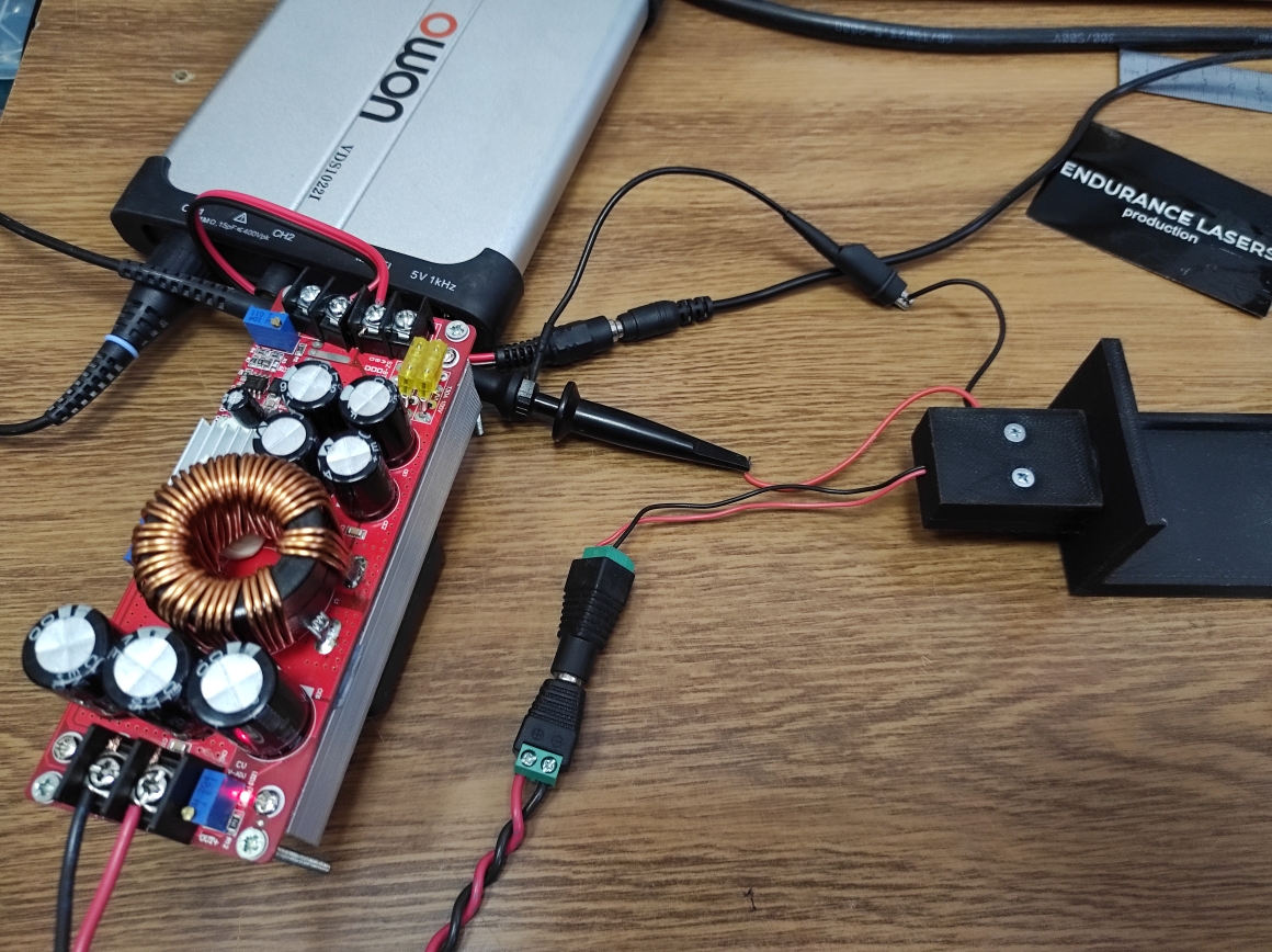
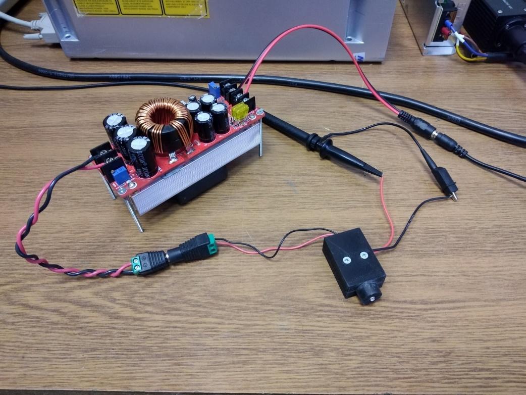
A universal laser pulse detector demo
A universal laser pulse detector in action

A universal laser pulse detector measurements
Photodiode features (the key component):
The photosensitive cell (effective) area is 1.37 mm2;
Service voltage 10 V
Spectral sensitivity range 0.4 – 1.1 µm
Maximum spectral characteristics 0.8 – 0.9 µm
Dark current, not above 5 nA
Integral current sensitivity, no less than 0.02µA/lx
Intrinsic time constant (U = 10 V), not above 10ns
Intrinsic time constant (U = 60 V), not above 2ns
As seen from the photodiode characteristics, its time resolution is 2 ns at a supply voltage of 60V. So, with its help, it will be possible to measure pulses with a duration of no more than 10 ns. While the oscilloscope should have at least 80MHz bandwidth. If its bandwidth is less, then 10 ns pulses will appear longer and with shape distortions.
To determine the required load resistor resistance you can use the ratio R*C << the measured pulse duration, where R is the resistor resistance, C is the oscilloscope input capacitance. The oscilloscope input capacitance should be specified in its specifications, but the approximate C value can be considered as 20pF (0.02nF). That is, if we measure a 10ns pulse then R*C should be several times less (preferably by an order ), but no more than 1-3. R = 1/C = 1/0.02 = 50 ohms.
Pulse detector circuit
Safety precautions when using the pulse detector
In order not to damage the photodiode it is necessary to protect it from direct laser radiation. Only unfocused scattered laser radiation is safe for the photodiode. To scatter the laser radiation it is necessary to install a light signal attenuator between the laser and the photodiode. One or more sheets of white paper or a piece of frosted glass can be used as a light attenuator. It is also possible to place the photodiode not in the center of the laser spot but at its edge. In addition to it, you can also install a special mirror between the laser and the light attenuators to reflect most of the laser beam energy.
Photodiode linearity range
In the process of measuring the photodiode must operate in the linear mode, otherwise, the pulse shape will be distorted, and the measurements of its duration will be incorrect.
To determine the linearity range of the photodiode it is necessary to send a light signal to it and register the signal voltage amplitude on the load resistor with the help of the oscilloscope. Then a light attenuator is placed in front of the photodiode and it is registered how much the amplitude has decreased percentage-wise. After this, it is necessary to increase the light signal power and again record the signal amplitude without and with the light attenuator in front of the photodiode. If the percentage amplitude change is the same as in the previous measurement then the photodiode operates in the linear mode and it is necessary to increase the light signal power again and continue measurements. If the percentage amplitude change differs from those obtained in the previous measurement then the photodiode operates in the non-linear mode.
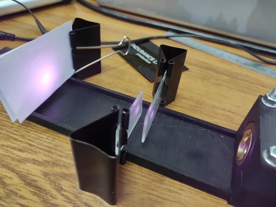
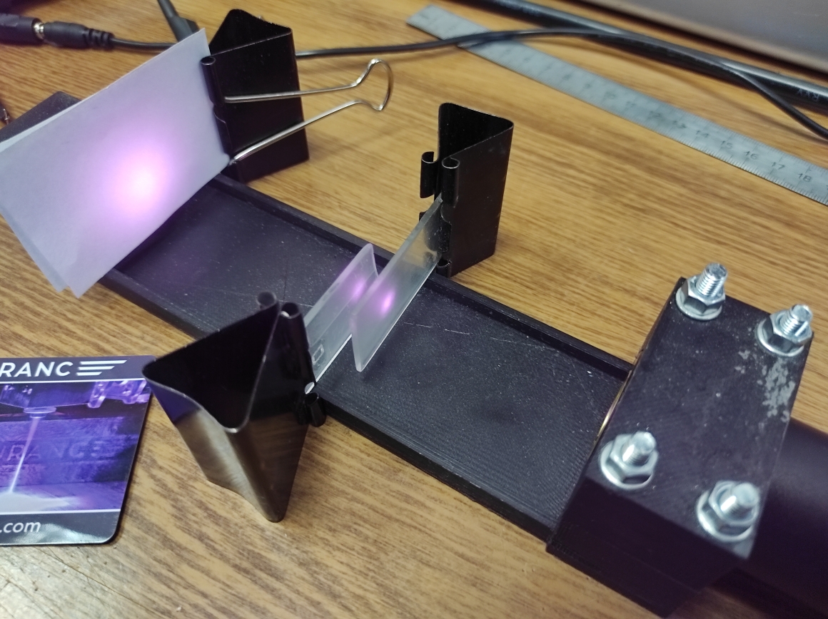
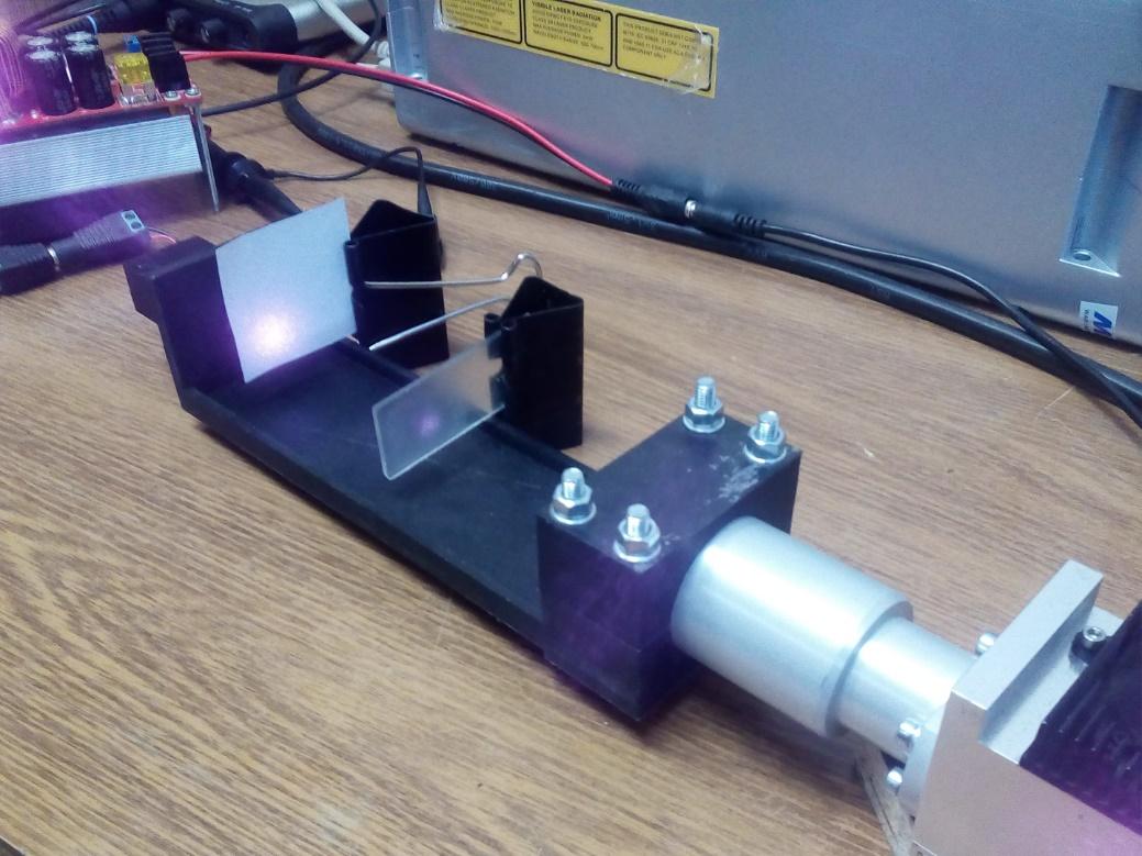
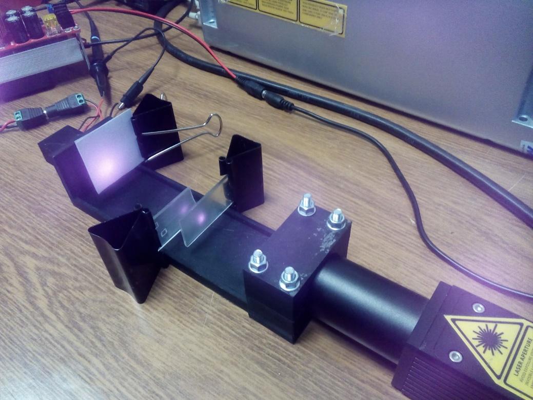
As a light signal source, a diode laser controlled by a PWM signal can be used. The laser power will be controlled through the voltage applied to the laser diode. Frosted glass will be good as a light attenuator. 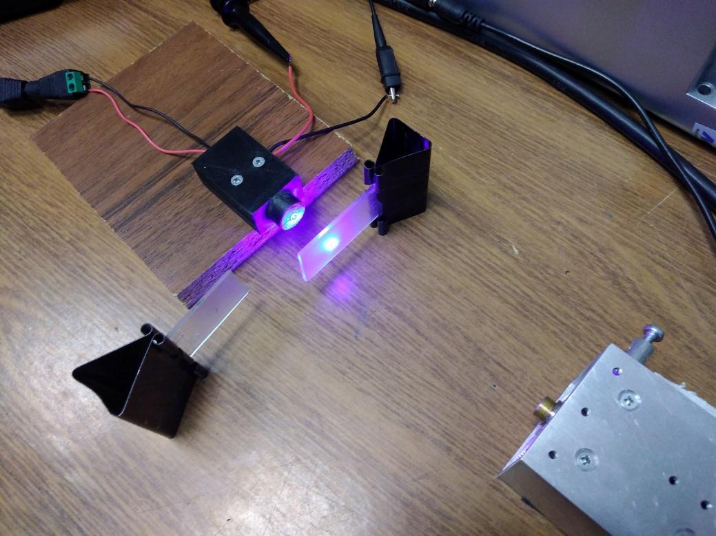
Here we use two frosted glasses. One is used to protect the photodiode from direct laser radiation, the other as a light signal attenuator for measuring its amplitude decrease. 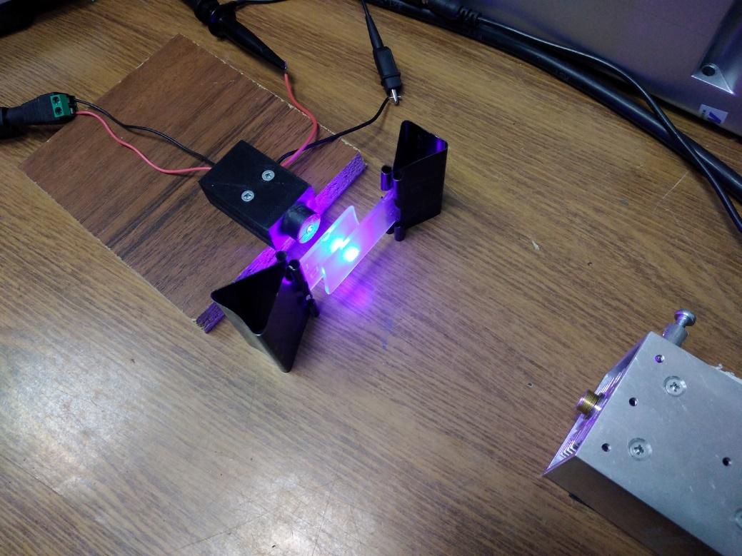
In the process of finding the photodiode linearity range, the location of the photodiode, laser, and signal attenuators should not be changed. As the second signal attenuator in front of the photodiode is to be installed and removed in the measuring process, it is important that it is put at the same place every time. The range between the detector and the laser, as well as the location of the signal attenuators between them, are chosen in such a way that when the laser is turned on at low power it is possible to detect the pulse and see it on the oscilloscope.
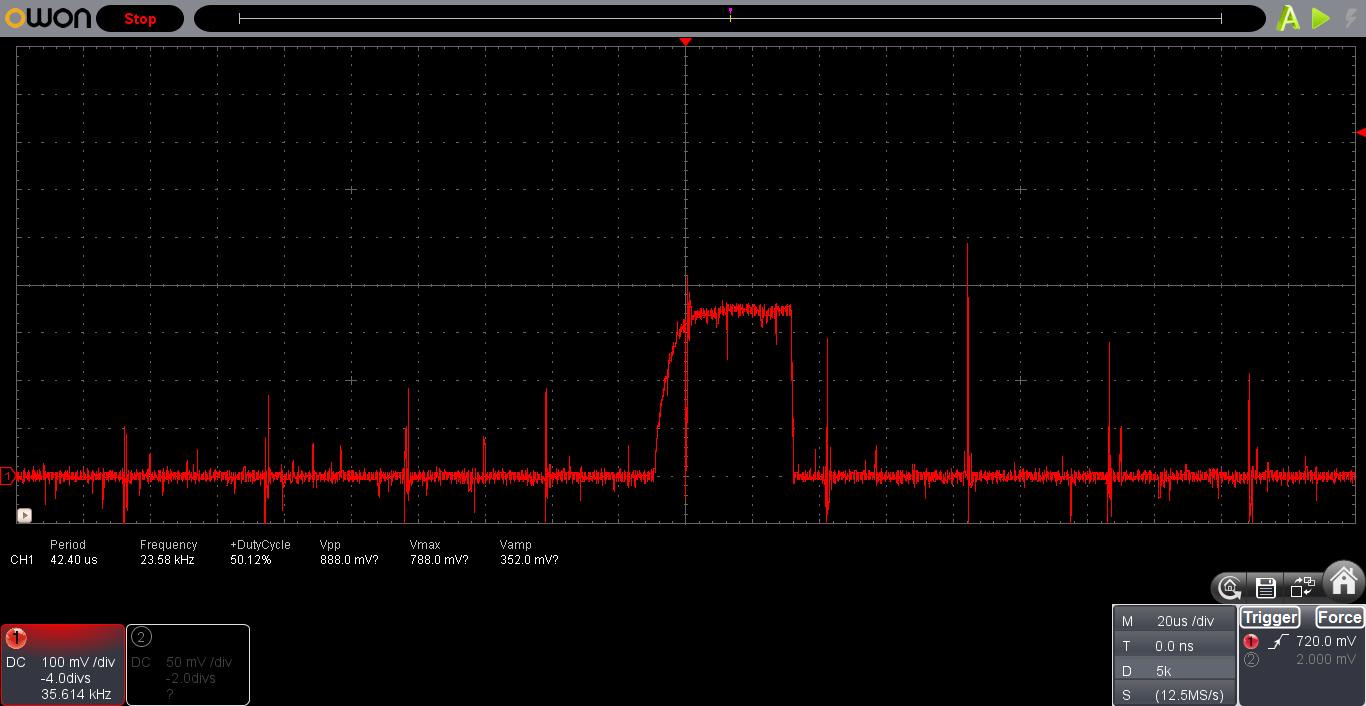
The laser is turned on at low power. Via the PWM signal, the laser is given the light pulse duration, which is 40 μs. Only one frosted glass is positioned between the laser and photodiode, the pulse amplitude is 350mV.
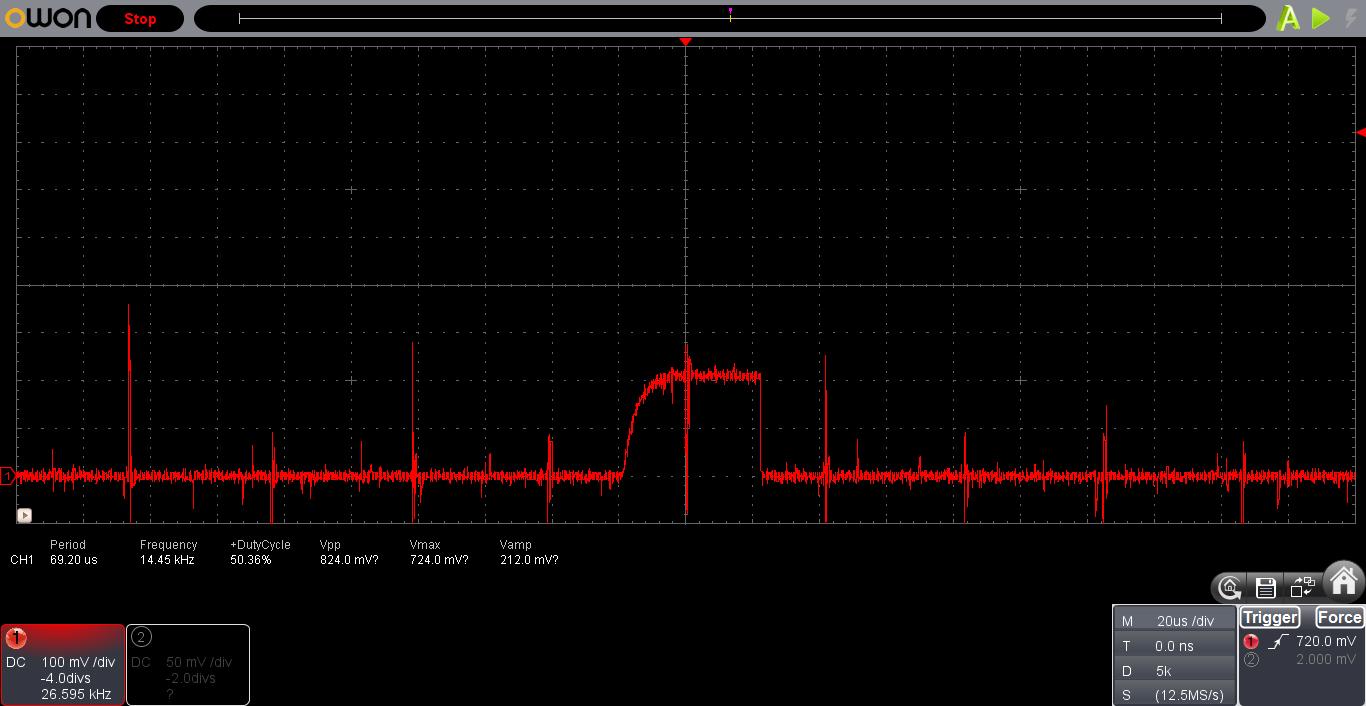
After installation of the second frosted glass in front of the photodiode, the pulse amplitude went down to 210mV, that is 60% of 350mV. So, the light signal has weakened by 40%.
By increasing the voltage applied to the laser diode, we increase the current passing through it. As a result, the power of the laser light signal is increased. Thus, the pulse amplitude registered by the detector will increase too.
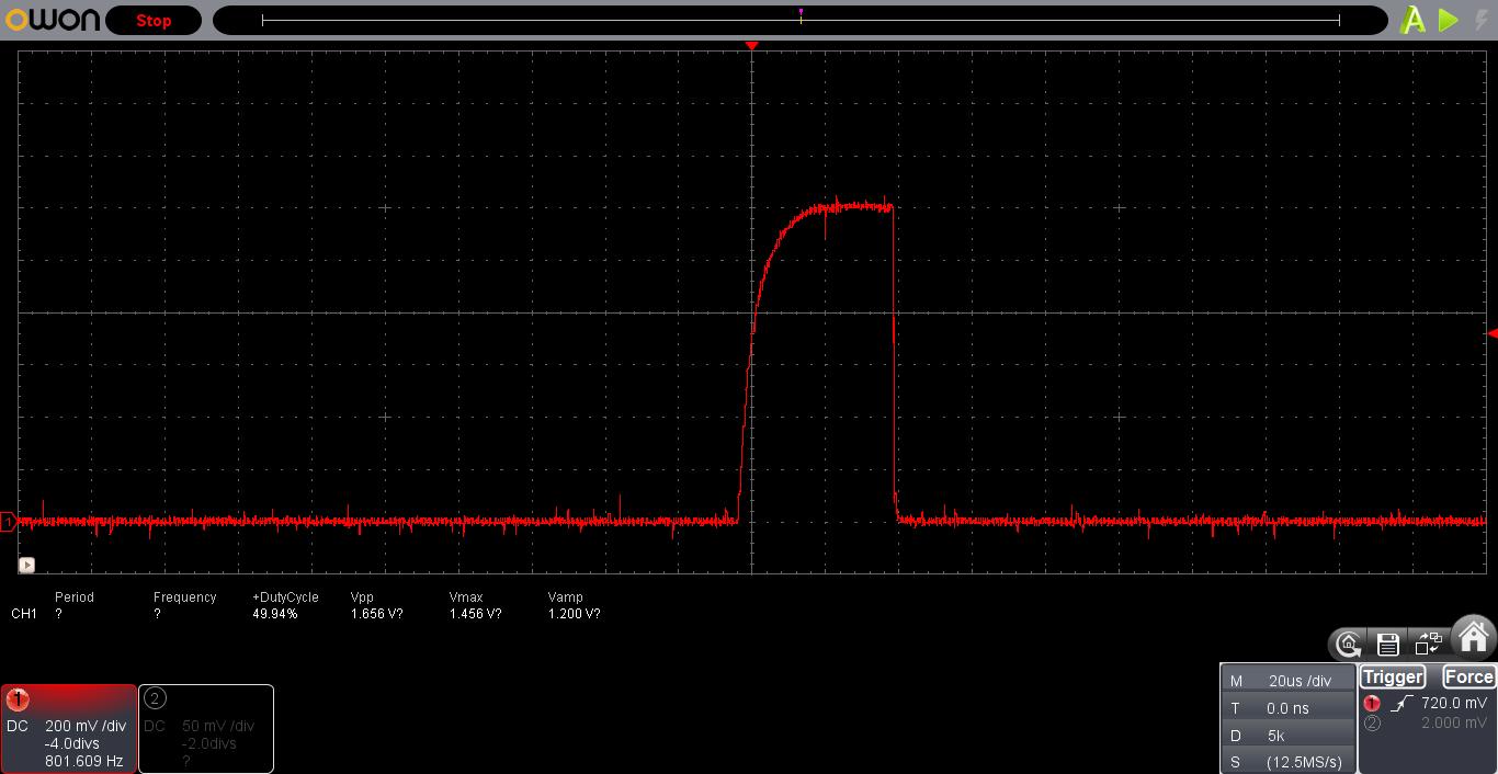
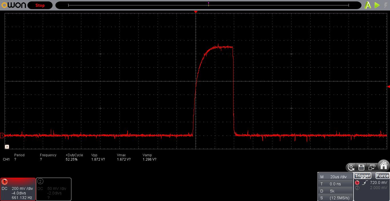
Gradually, we increase the power of the laser light and measure the amplitude decrease after each light flux increase. As a result, the amplitude reached 1200 mV.

After the second frosted glass installation in front of the photodiode, the amplitude dropped to 720mV. The amplitude drop is still 40%. So, the photodiode is in the linear mode.
The next increase of the light signal power. The amplitude is 1300 mV.

After the second frosted glass installation in front of the photodiode, the amplitude dropped to 800 mV. The amplitude drop is now 38.5%. So, the photodiode is in a non-linear mode.
We increase the light signal power again. The amplitude is 1500 mV.

After the second frosted glass installation in front of the photodiode, the amplitude dropped to 950 mV. The amplitude drop is still 37%. This confirms that the photodiode is in a non-linear mode.
Based on the measurements, we can argue that the photodiode operates in the linear mode if the amplitude of the registered pulse does not exceed 1200 mV.
Methods and the result of the pulse measuring
The detector and laser are positioned apart from each other with one or several light signal attenuators in-between them. The distance between them and the number of the attenuators depends on the laser power and is found by experiment. Thus, for the beginning, you can position the laser and the detector at a distance of 30, 50 or 100 cm from each other and place a few attenuators between them. After firing the laser (turn it on at low power first ), perhaps, you will need to change the distance between it and the detector, the position and number of the attenuators. Check the oscilloscope readings: if the pulses are not registered, then you need to shorten the distance between the laser and the detector/attenuator’s position/their number. It is also necessary to make sure that the photodiode operates in the linear mode, and if the pulse amplitude is too large (in our case it exceeds 1200 mV), then you need to perform reverse actions.
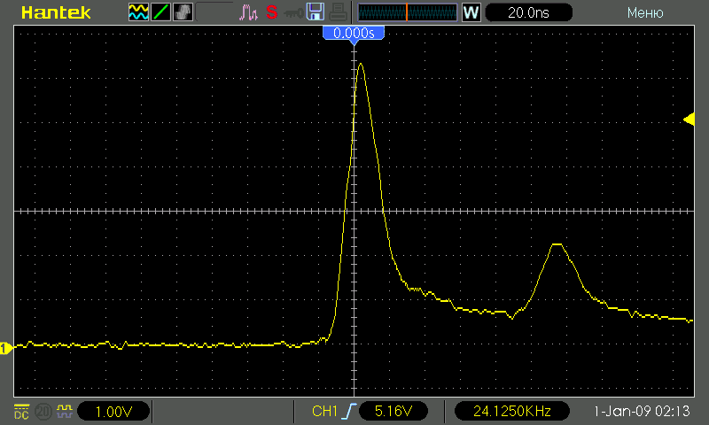
Diode laser measurements
We used frosted glass as a signal attenuator. 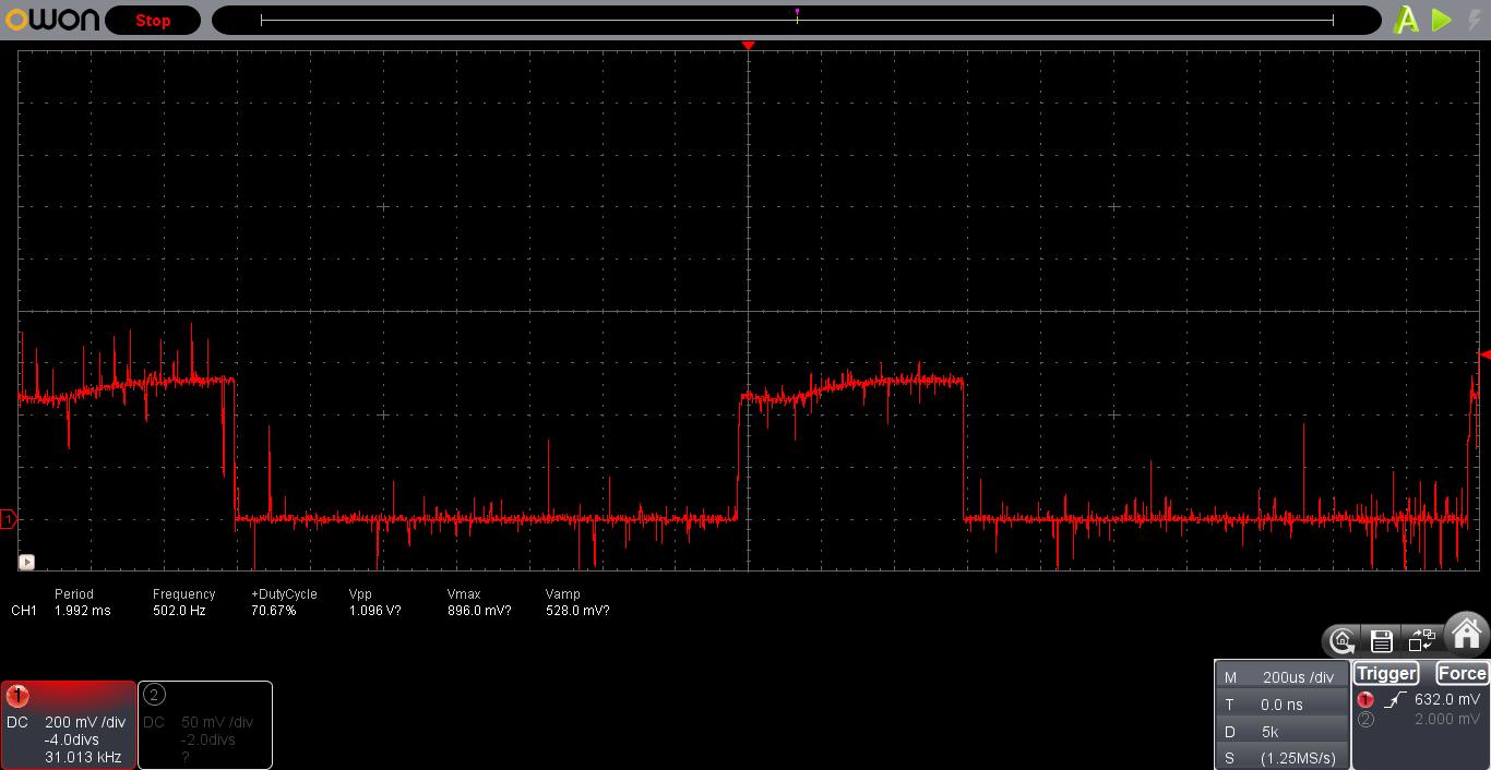
The pulse duration depends directly on the duty cycle of the control PWM signal Therefore, the pulse shape will be close to a rectangular one. In the current measurement the PWM signal frequency is 500 Hz, the duty cycle is set at 30%, the scope sweep is set at 200μs. The pulse duration is 600 μs (it is measured at the middle of its amplitude). The pulse amplitude is 520 mV.
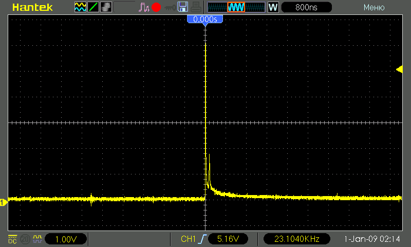
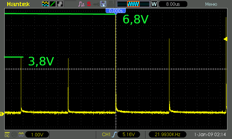
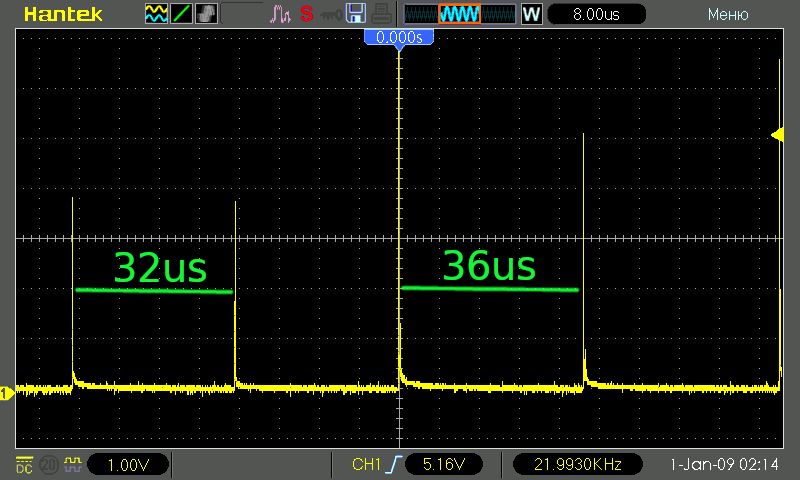
Solid-state DPSS laser measurements
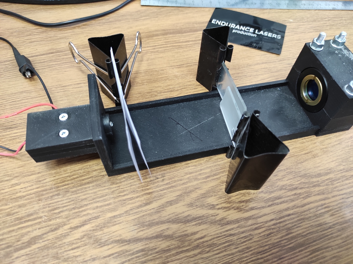
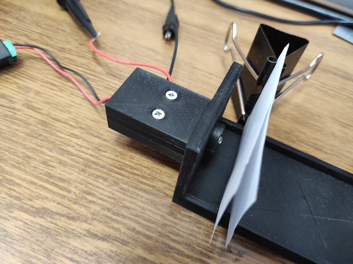
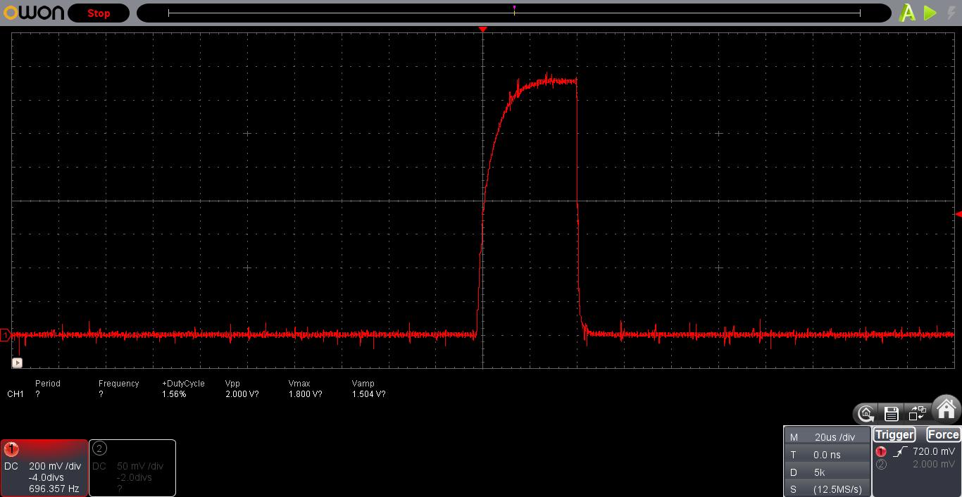
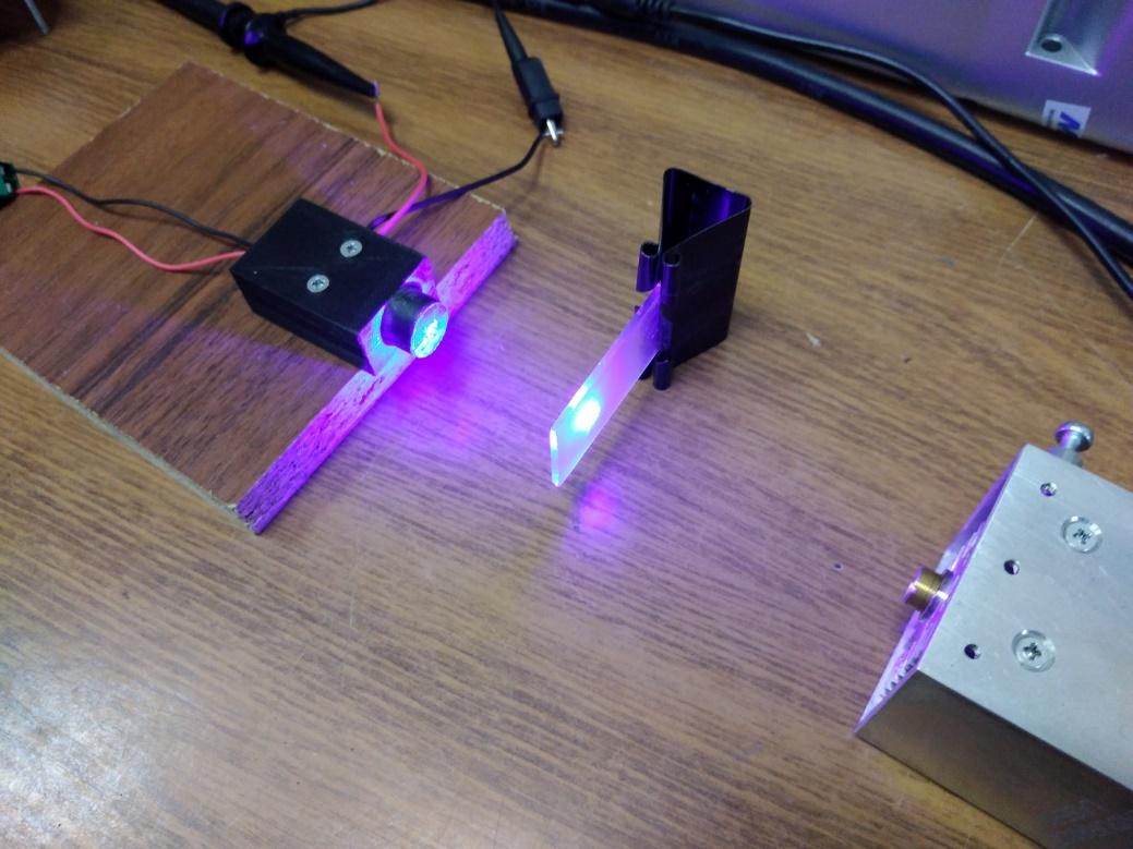
A telescope without a focusing lens is installed at the laser output. The laser is not focused. Since the laser wavelength is 1064 nm, and the laser spot is not visible to the naked eye, a special fastener is used to position the photodiode in the center of the laser spot. Frosted glass and one sheet of white paper are used as a light signal attenuator.

The laser power is 100%.
Here the pulse shape does not depend on the control signal. The scope sweep is set at 50 μs. The pulse duration is about 12-14 μs. The pulse amplitude is 1100 mV.
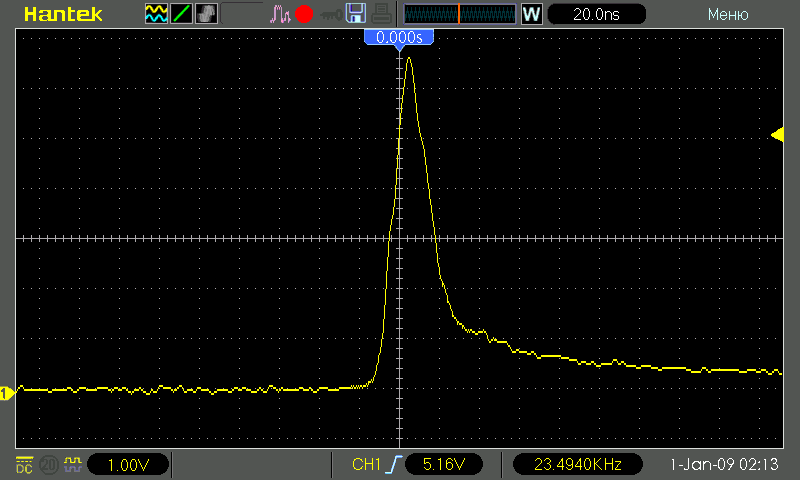
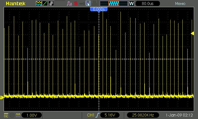
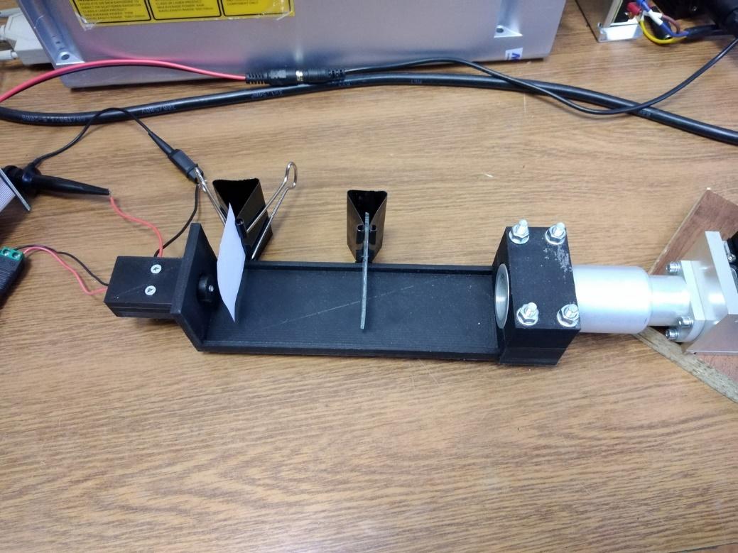
Raycus fiber laser measurements
Since the laser wavelength is also 1064 nm, and a telescope without a focusing lens is installed at the laser output, the measurements are performed in the same way as with the DPSS laser. Two frosted glasses and two sheets of white paper are used as a signal attenuator.

The laser power is 100%.
The pulse shape does not depend on the control signal. The scope sweep is set at 200 μs. The pulse duration is about 100 μs. The pulse amplitude is 1000 mV.