Endurance fiber-coupled diode laser 445 nm wavelength


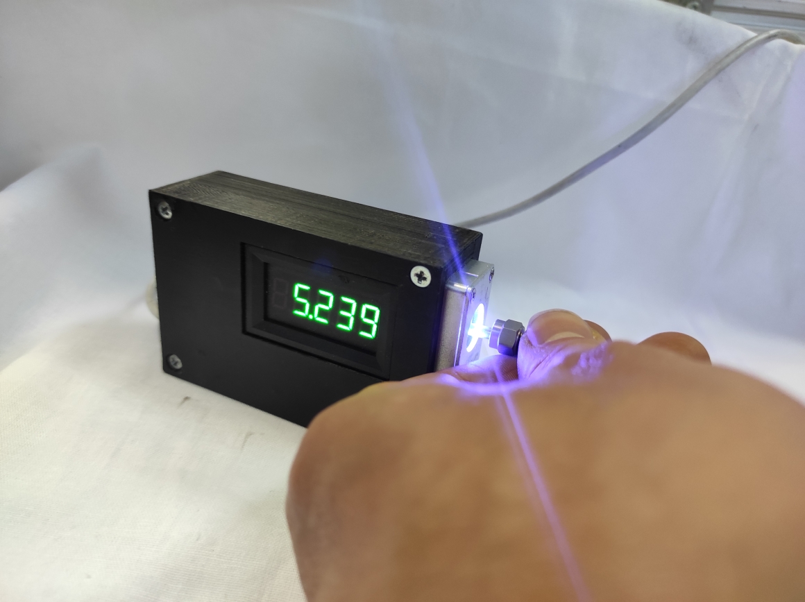
5.5 watt optical output SMA 905 output
Our laser system specification
Wavelength (nm) 445+- 2 nm
Operating mode CW
Output power (mW) 1-5500
Fiber core diameter (um) 100/ 200/ 400 / 600 / 800 /1000
Fiber connector FC/ PC or SMA905
Power stability (rms, over4h) <5%
Operating Temperature(℃) 15-30
Power supply 5VDC 90-264VAC
Modulation TTL/ Analog (Optional)
Expected lifetime 10000
Warranty 6 months
Note: Customized work available on request.
Estimate ВРР = (laser beam radius) х (numeric apperture).
Laser beam radius 0.1mm, NA 0.22 = 220 mRad.
BPP ~ 22 mm*Mrad
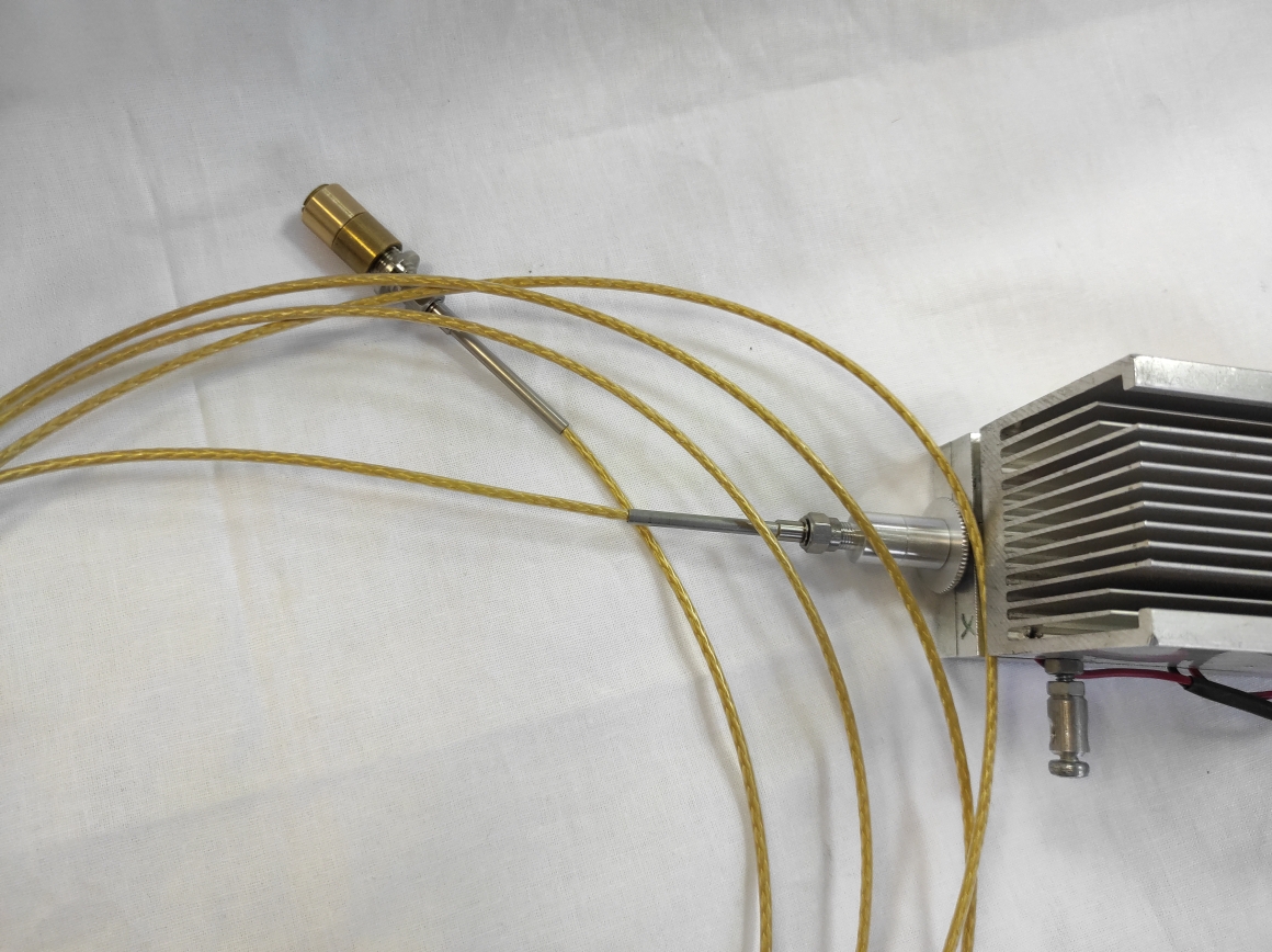
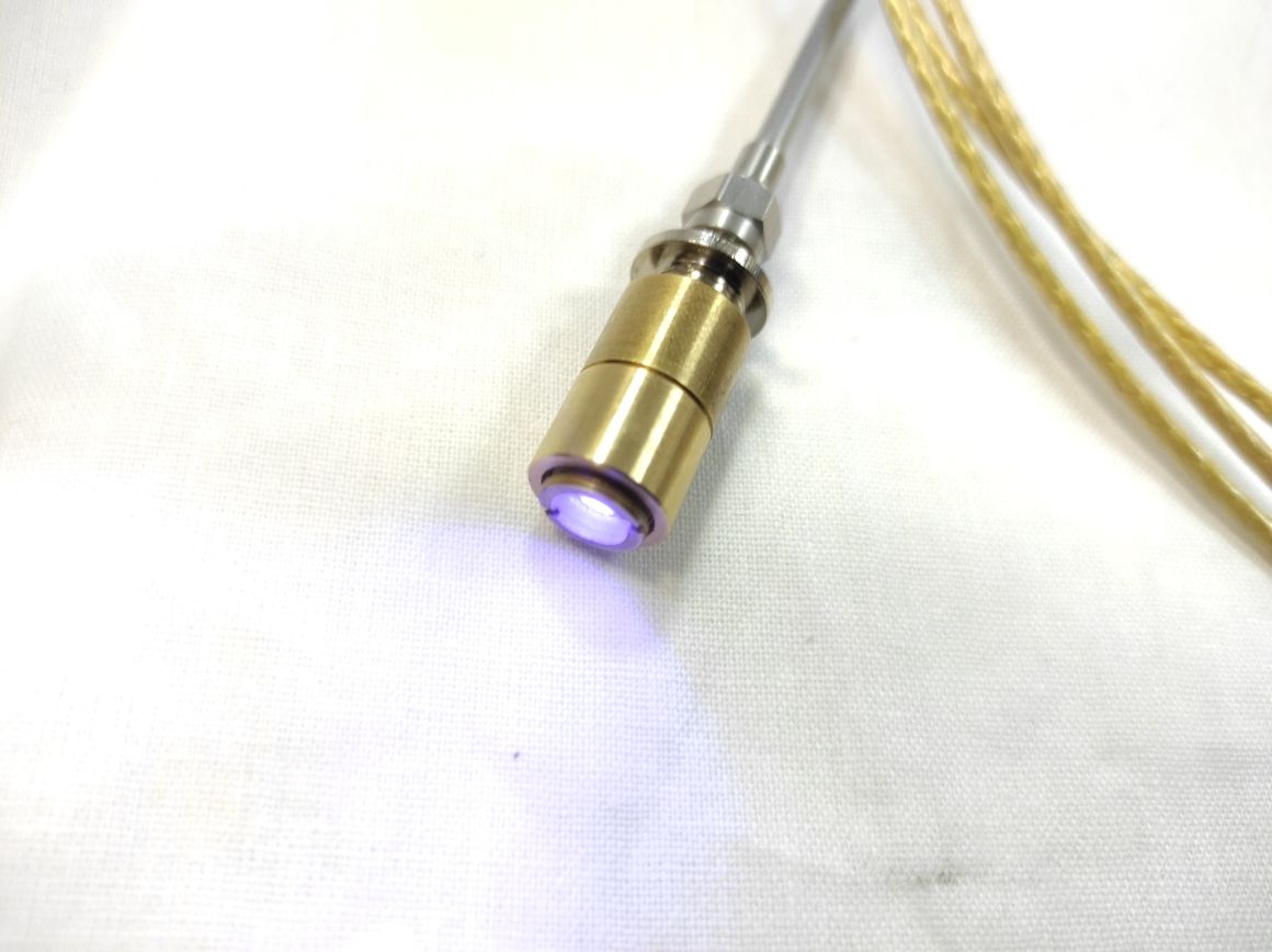
Fiber Coupled Laser Module with 5.5 watt (5500 mw) optical laser power output
Endurance offer different core diamter fibers: 105-1000 um MM fiber or SM fiber.
If you need a special optical system – we can make it.
The FC series (Fiber Coupled Laser System) integrates laser diode, laser cavity, fiber coupled optics, laser power supply, LD current and crystal temperature control into ONE box. The power is available for 1mW-15W with different dimensions. The characteristics of compact design and convenient functions make it very suitable for pumping, scientific research, industrial and medical applications.
Special offer multi-wavelength fiber coupled laser system are designed with integrated electronics and easy operation. 2~6 wavelengths can be combined into one box. USB or RS232 connector is optional.
Emdurance lasers can supply the even beam distribution of laser modules and laser systems, features a flat beam profile with different wavelengths. They are suitable for the fields of medical treatment, ultraviolet curing, fluorescent detection, criminal investigation and scientific research.
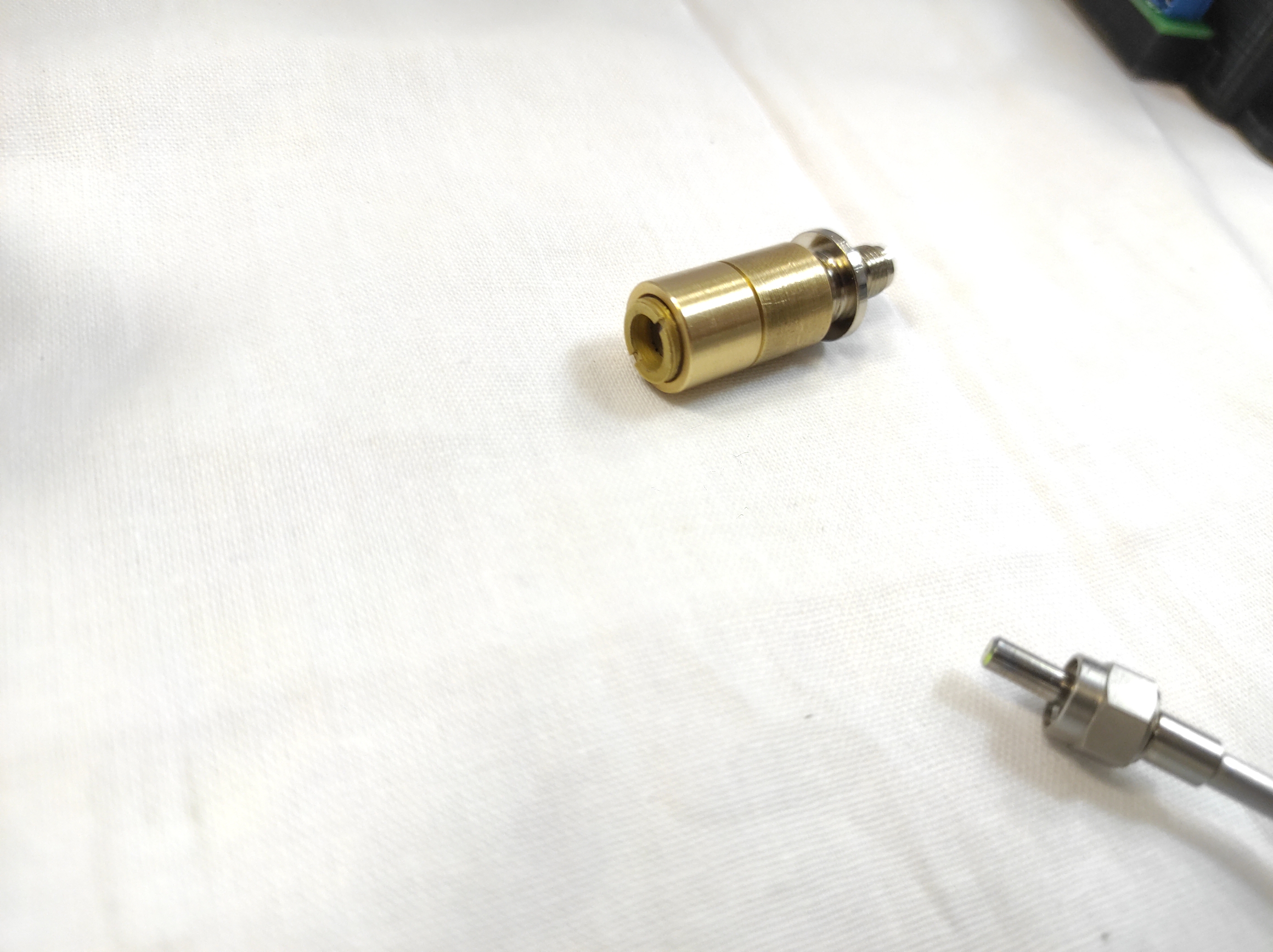
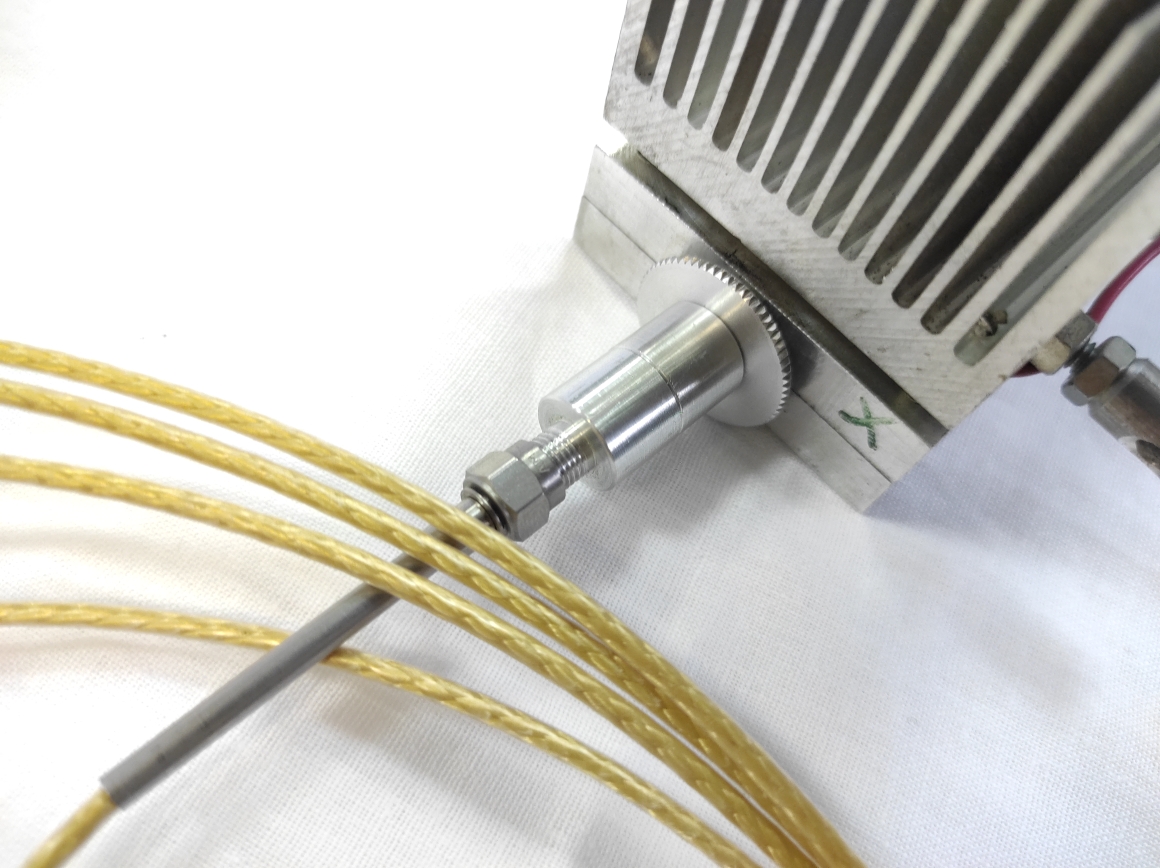
Endurance Fiber Collimator design for
Single-mode fiber with core diameter 4-9 μm
Multi-mode fiber with core diameter 50-1000 μm
Used to collimate the beam at the end of fiber
Focus adjustable collimator optional
We can develop a green and a red laser-based system designed and performance-optimized to be the ultimate tool for trace evidence detection, particularly of latent prints. It is a compact forensic light source for use in crime labs and at crime scenes, as well as for covert and homeland security applications.
Focusing on the Radiation Coming out of the Fiber
Input data:
fiber diameter – dcore = 800 µm
numerical aperture NA=0.22
radiance power 50 W at a wavelength of 0.8 µm
distance between the surface of the end lens and the focus Lfoc = 20-25 cm
A dual-lens scheme is usually used for this. The first lens collimates the beam, the second one focuses it. The second (end) lens focus spot diameter equals:
where: fcol and ffoc are focuses of the collimating and focusing lenses, correspondingly.
This equation is written in the geometric optics approximation. Since the focal length of the focusing lens is given, there is only one free parameter with which we can change the spot size. This parameter is the focus of the collimating lens fcol. Theoretically, by increasing this focus, it is possible to obtain an arbitrary small focal spot. If we take into account the wave properties of light, it appears that the minimum theoretical spot size is limited below by a value of approximately dcore NA, i.e., about 180 μm. Practically, it is not possible to obtain a spot of this size due to the aberrations of any real lenses (even aspheric ones).
Besides, a decrease of the focal spot diameter means a focus waist-length reduction. In the geometrical optics approximation for the focal depth Lwaist we can write:
Here, by the focal depth is meant the length of such a segment around the focal point within which the beam diameter differs by no more than 2 times.
With the increase of the collimating lens focus its diameter dcol must increase proportionally according to the formula:
Let’s consider the possibilities of focusing when real lenses are used.
Let’s take two identical quartz lenses, fcol = ffoc = 250 mm
Their parameters must be as follows:
the curvature radius ROC= 112.5 mm
the diameter – no less than 105 mm
the thickness – no less than 13 mm
Let’s take lenses with a diameter of 105 mm and a thickness of 14 mm. Since in a wide beam the effective focus (the distance to the maximum focus point) is less than the lens focus, we’ll position the lenses in such a way that the distance between the fiber end and the first lens is approximately the same as the distance between the second lens and the minimum focal spot. The distance from the fiber end to the first lens was 230 mm.
Fig.1 shows the beam path in the system (the fiber is at the left)
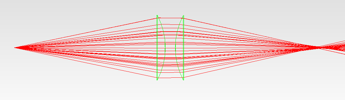
Fig. 1. The beam path in the system with two identical quartz plano-convex lenses with a focus of 250 mm.
Calculations show that aberrations in such a system are large. Fig. 1 proves this. The effect of the aberrations can be assessed numerically if you look at the following figures. Fig. 2 demonstrates how the spot diameter changes at a certain power level depending on the distance from the end lens. We consider the diameter at a certain power level because the spot has no clear outline (fig. 4).
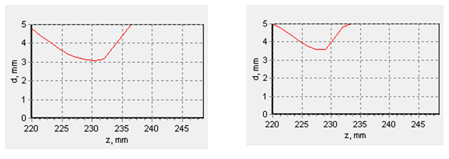
Fig. 2. The dependence of the spot diameter from the distance to the second (end) lens at power levels of 80% (left) and 90% (right).
And here is the maximum spot intensity at different distances:
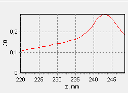
Fig. 3. The maximum spot intensity depends on the distance from the end lens. The intensity relative to the intensity at the fiber end is plotted along the lateral axes.
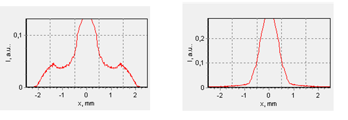
Fig. 4. Radial profiles of the spot intensity at a distance of 227 mm from the end lens (the minimum spot size point at a power of 90% power) are on the left and at a distance of 243 mm from the lens (the maximum intensity point) are on the right. The intensity as well as in fig. 3 is normalized to the end fiber beam intensity.
As it is seen, the aberrations of this system decrease the focal spot intensity by more than three times. Quartz is a poor lens material in terms of aberrations due to its low refractive index. To reduce aberrations, heavy glass lenses are often used.
For example, if we use LASF9 glass from Schott with a refractive index of n=1.83 at a wavelength of 0.808 µm then the lens parameters for the focus f=250 mm should be:
the curvature radius of ROC= 208 mm
the diameter – not less than 105 mm
the thickness – not less than 8 mm
Let’s take a lens with a thickness of 10 mm, to be more precise. Then the symmetrical position corresponds to the fiber-1st lens distance and the 2nd lens-focus distance, approximately 240 mm.
Calculation:
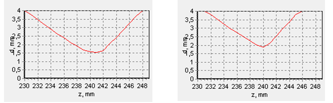
Fig. 5. The dependence of the spot diameter from the distance from the 2d lens at 80% power (left) and 90% power (right).
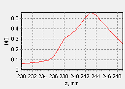
Fig. 6. The maximum spot intensity depends on the distance from the 2d lens. The intensity relative to the intensity at the fiber end is plotted along the lateral axes.
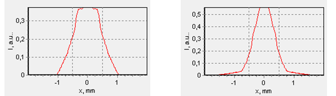
Fig. 7. Radial profiles of the spot intensity at a distance of 240 mm from the 2d lens (the minimum spot size point at a power of 90% power) are on the left and at a distance of 243 mm from the lens (the maximum intensity point) are on the right. The intensity is normalized to the end fiber beam intensity.