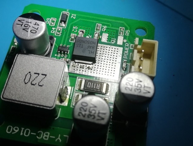
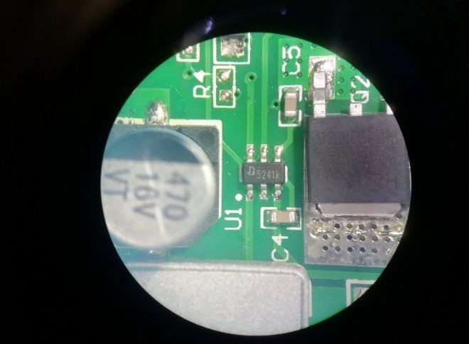
Exploring weaknesses and potential troubles in the electronics circuit.


This laser diode is built on the basis of the QX5241 High-side Sense High-brightness LED Driver chip.
The typical circuit positioning of the QX5241 chip is shown in the picture below.

The printed laser circuit of the Ortur laser driver has no essential improvements if we compare it with the typical QX5241 chip application.
The only significant addition to the typical QX5241 chip application will be a capacitor connected in parallel to the laser diode, which is marked as C1.
The operation of the circuit is based on the principle that the current in the circuit cannot increase instantly and due to the L1 inductance the current will increase gradually. The QX5241 chip drives the Q1 transistor. When Q1 is on, the laser diode current starts to build up. The laser diode current is set by the resistance of the resistor Rcs, and is calculated by the equation:

The Rcs resistance in the circuit of the Ortur laser driver is 0.055 Om (two 0.11Om resistors are connected in parallel).

When we substitute these data in the equation the laser current should be approximately 3.6A. This value is confirmed in practice and corresponds to the current indicated on the shield of the Ortur laser.

Ortur laser inspection. Remark 1.
In the accompanying document to the chip we see that the maximum output current is 2.5A.

It is known that every chip manufacturer has their “safety margin”, but how much it is nobody will tell.
Exceeding of the maximum parameter can result in unpredictable chip operation. As the laser is powered by a supply voltage of 12V, an uncontrolled voltage supply will lead to an uncontrollable increase of the current in the circuit.
Ortur laser inspection. Remark 2.
Another specific feature of the chip is the Maximum Dimming Frequency value, which is 5 khz. In the laser this is the maximum PWM frequency of your CNC controller. In the Ortur driver circuit, the chip pin is connected via the resistor to the PWM pin of the laser power connector. Again, exceeding of this value will prevent the chip from the correct control of the current in the circuit.

Ortur laser inspection. Remark 3.
The Input Low-Level value is also very important. The QX5241 Dim input voltage is only 0.6V. Don’t forget that this is the value of the PWM signal voltage. This low voltage leads to a well-known fact of laser self-starting at 50-70% of the maximal power at the moment when the CNC controller turns on or when the PWM wire is not connected to the controller.
Ortur laser inspection. Remark 4.
This is actually not a remark but the key feature of the operation of this driver type. As we have mentioned already at the beginning of the article, a C1 capacitor is added to the typical QX5241 chip schematic. This capacitor is necessary to reduce the current pulsations in the laser circuit. When the Q1 transistor is closed this capacitor discharges via the laser diode. In doing so it prevents the radiation fail-fast during the chip switching.
Let’s have a closer look at it:
In the picture below we see a signal with a 1 khz frequency and an operation cycle of 10% is being sent to the PWM input.

The current going through the laser diode is shown in the picture below.

When a high-level signal (over 0.6V as the chip manufacturer claims) is sent to the PWM input, the QX5241 chip starts to open and close the Q1 transistor, the current in the laser circuit begins to increase. As soon as the PWM input receives a signal to turn off the laser, a low level signal turns on the laser. By the effect of the self-induction EMF in the coil L1 and C1 capacitor, the laser keeps on burning for about 70 us. This means that if the PWM frequency is high and you need to quickly turn on and off the laser, the laser will not have time to turn off during pauses.
Our website visitors complaint about Ortur lasers and that is why they come to explore Endurance lasers

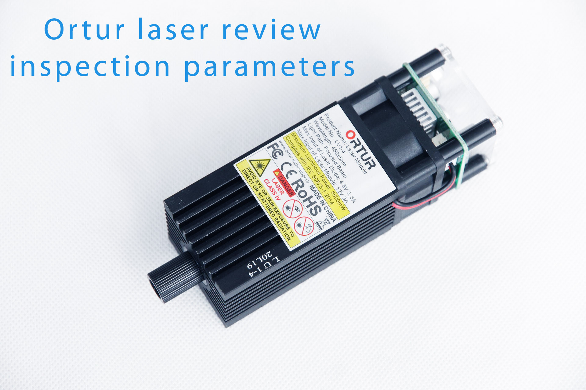
Review and an inspection of 5500 mW (5.5 watt) Ortur laser blue laser module
