Problem statement: demonstrate the operation of a plate for determining beams of different lasers.
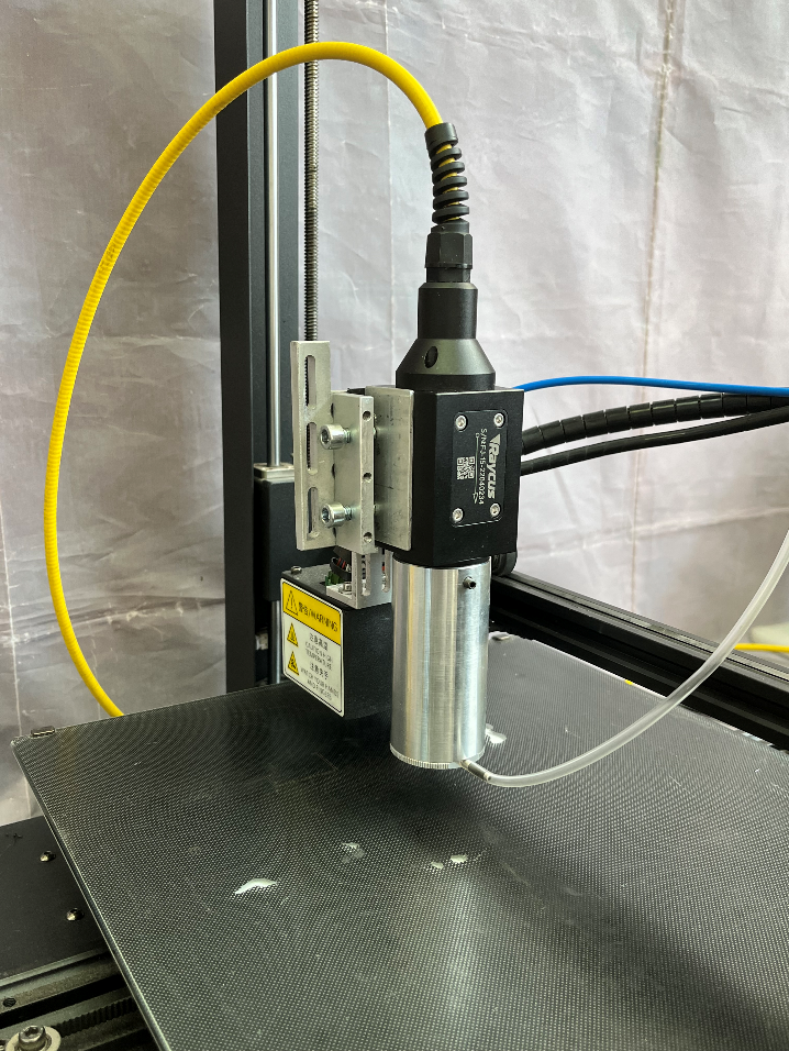
Infrared sensor cards visualize laser radiation in a wide spectral range and control the beam path for safe laser work. Due to the polymer base, the visualizers have high mechanical characteristics and high water resistance. In this work, we used four standard plates on a plastic substrate (reflection), shown in Figure 1.
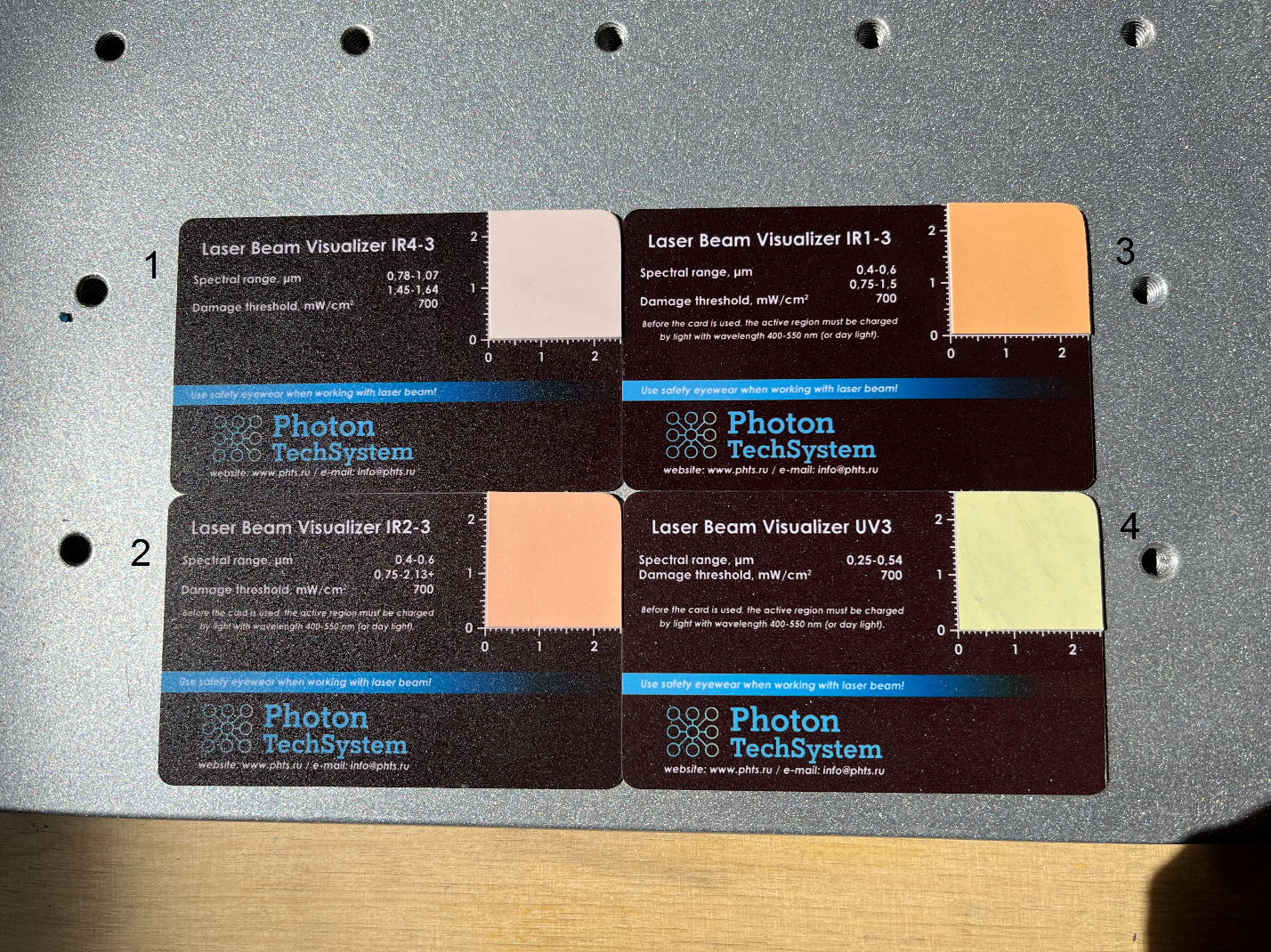
Characteristics of plate #1
The IR4 series renderers are a plastic card with a working surface made of luminescent polymer. Infrared sensor cards IR4 visualize laser radiation in the spectral range 0.78-1.07; 1.45-1.64 µm and control the beam path for safe laser work.
- Damage Threshold, mW/cm2 : >700
- Spectral Sensitivity, µW/cm2 : <2 (808 nm), <0.175 (960 nm), <100 (1550 nm)
- Color Emission: Green
- Charge Required for Emission: No
Characteristics of plate No. 2:
The IR2 series renderers are a plastic card with a working surface made of luminescent polymer. IR2 infrared sensor cards visualize laser radiation in the spectral range of 0.75-2.1 microns and control the beam path for safe laser work.
- Damage threshold, mW/cm2: >700
- Spectral sensitivity, µW/cm2: <150 (at 808 nm), <100 (at 960 nm), <100 (at 1550 nm), <2000 (at 1940 nm)
- Emission color: red
Characteristics of plate #3
Visualizers of the IR 1 series are a plastic card with a working surface made of luminescent polymer. IR1 infrared sensor cards visualize laser radiation in the spectral range of 0.75-1.5 microns and control the beam path for safe laser work.
- Spectral absorption ranges, µm: 0.75-1.5
- Damage threshold, mW/cm2 : >700
- Spectral sensitivity, µW/cm2 : <6 (at 808 nm), <2 (at 960 nm), <250 ( at 1470 nm)
- Emission color: red-orange
- Requires charge for emission: Yes
Plate Specifications #4
UV 3 series visualizers are a plastic card with a working surface made of luminescent polymer. Ultraviolet UV 3 sensor cards visualize laser radiation in the spectral range of 0.25-0.54 µm and control the beam path for safe laser work.
- Damage threshold, mW/cm2: >700
- Emission color: blue.
- Before using the cards, you need to charge them under daylight for about 5 minutes.
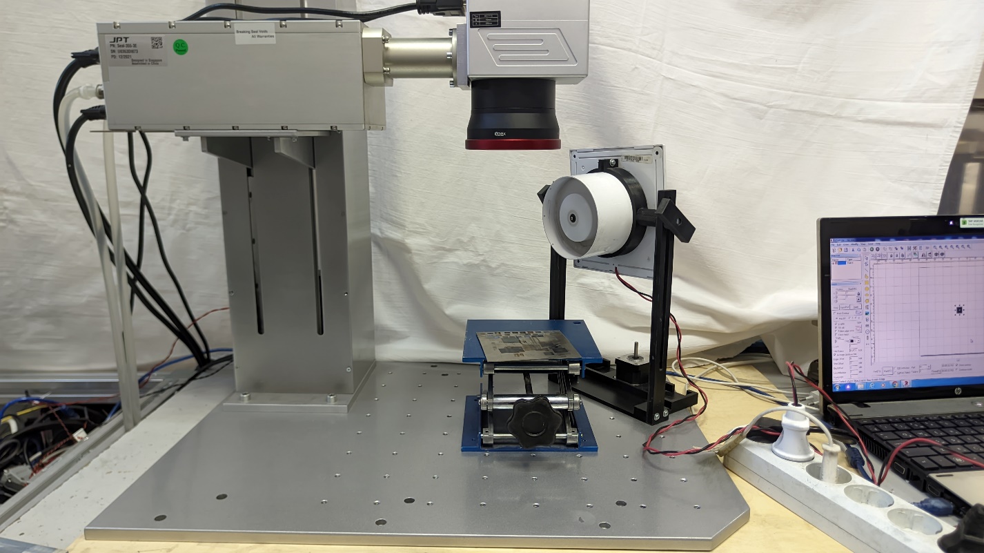
The first experiment was carried out with the JPT laser seal -355 with a wavelength of 355 nm, with an average power of 3 W (Figure 2).
We also tried to use a plate designed to indicate a beam of a different wave
A)
B)
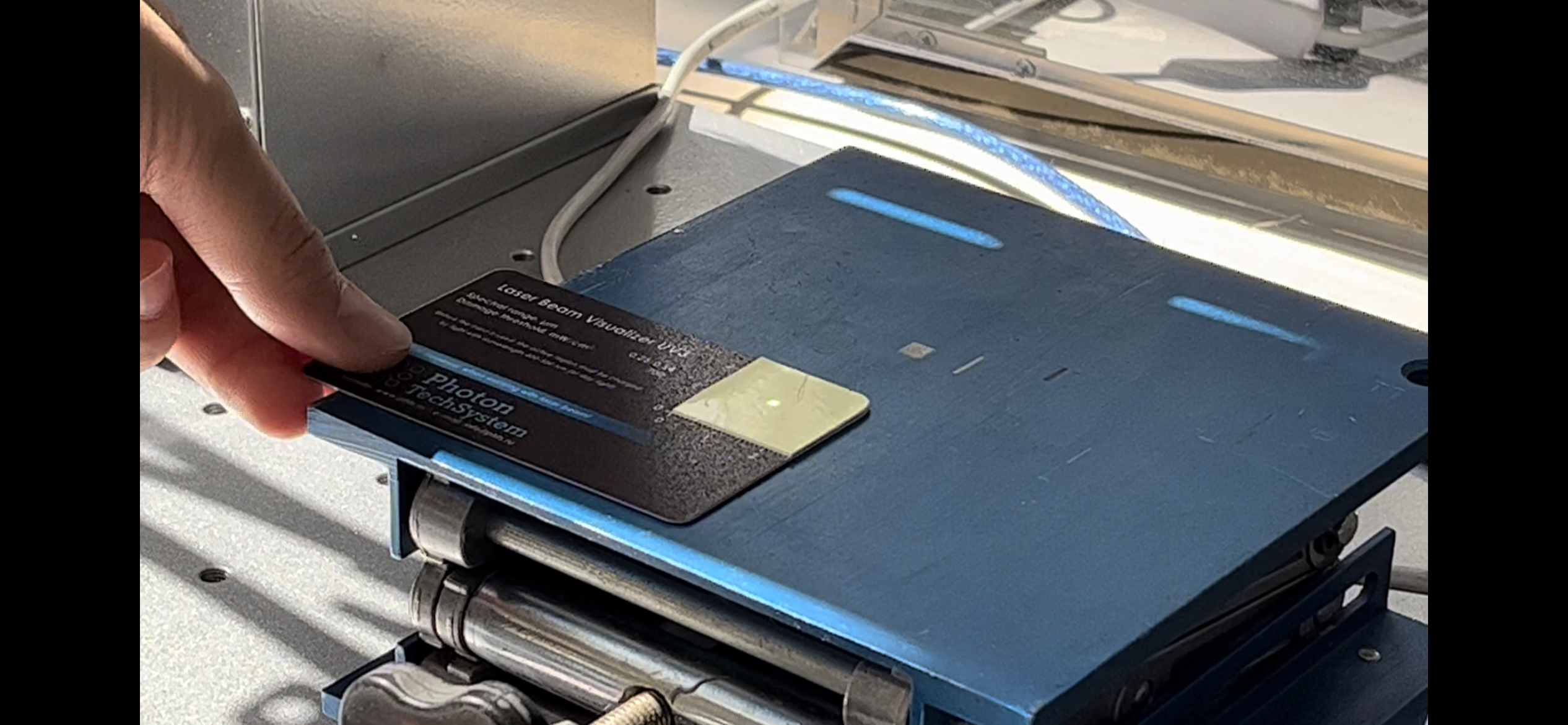
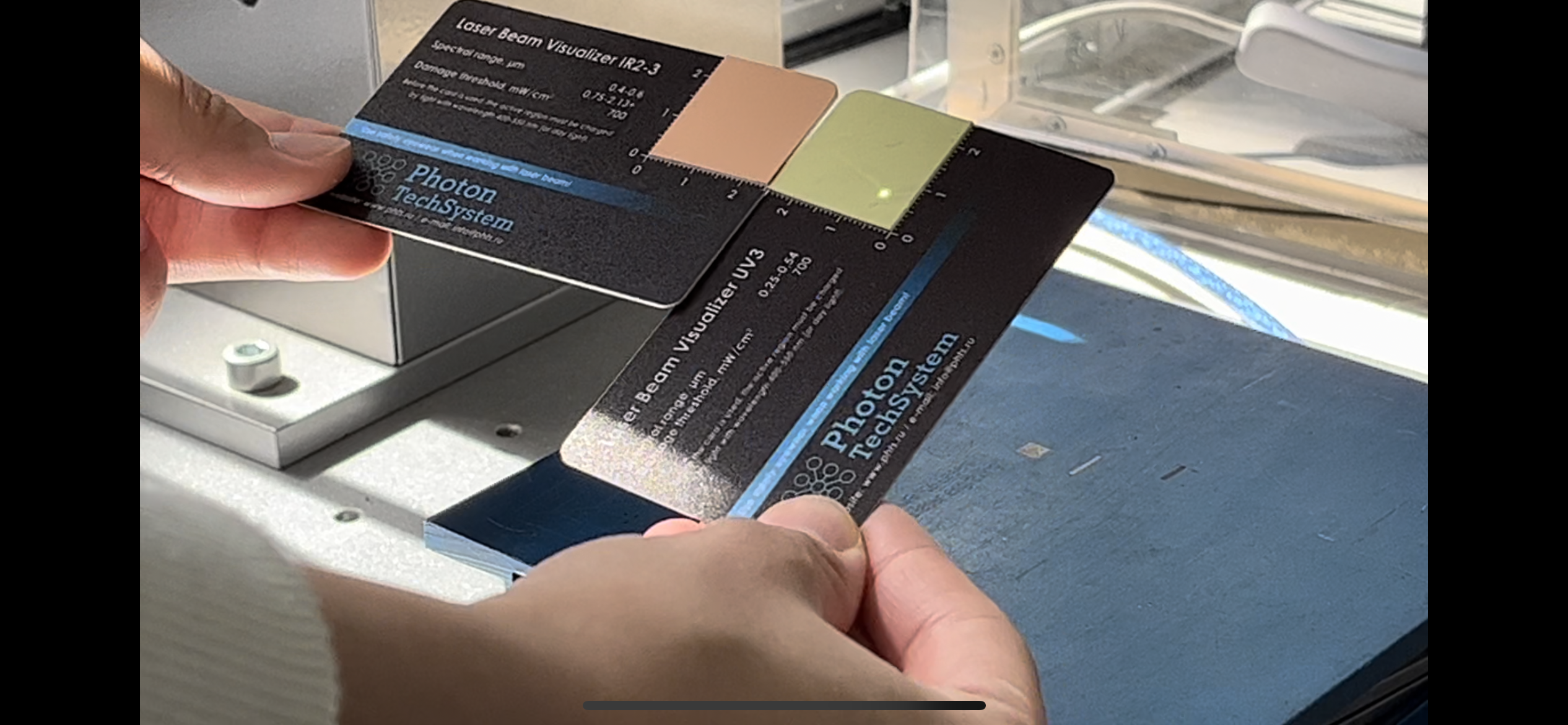
Figure 4 – Demonstration of the JPT laser beam seal -355.
A) IR 1-3 for the spectral range 0.4-0.6 µm. B) UV 3 for the spectral range 0.25-0.54 µm.
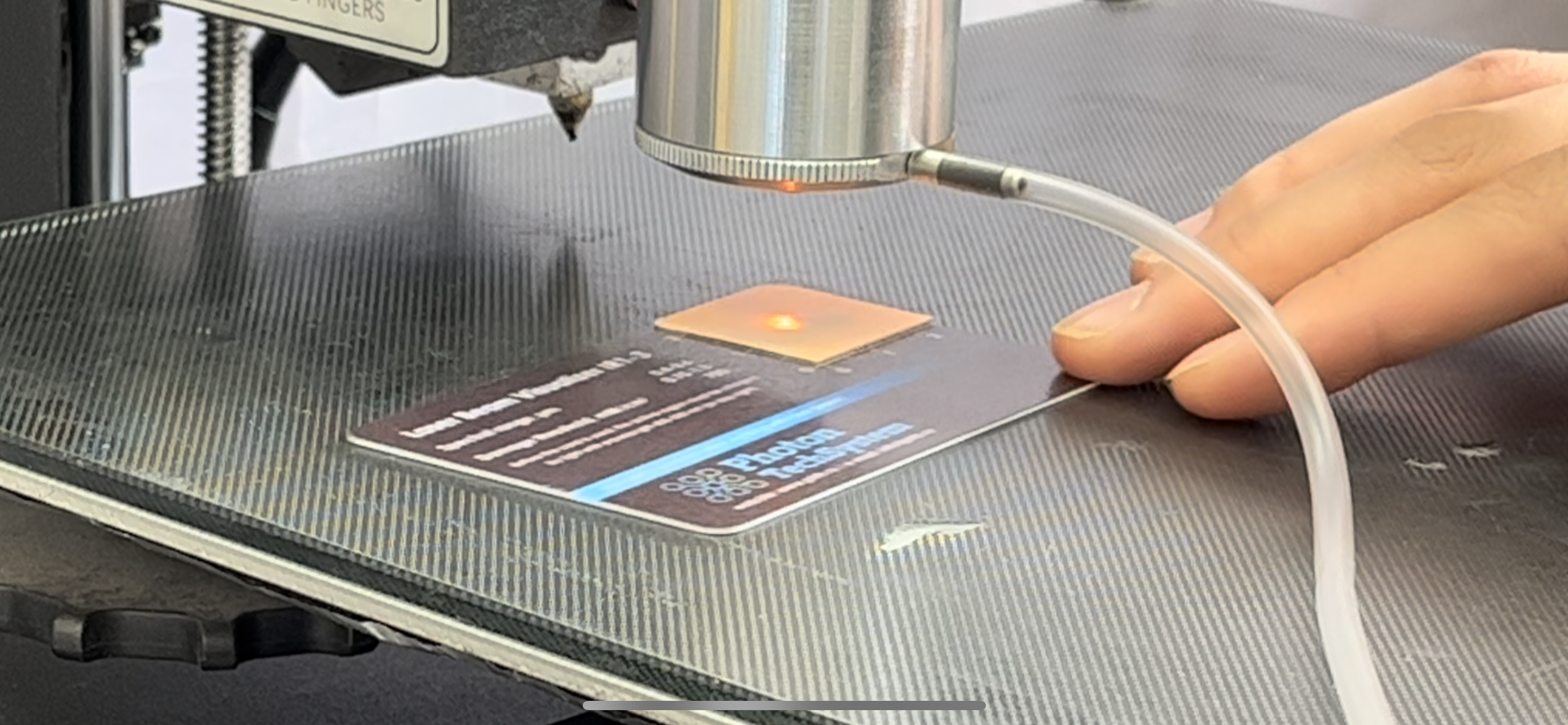
Note that the first map (Figure 4 A) does not represent the actual laser beam scatter circle. From this we conclude that it is important to correctly select the visualizer for the wavelength of the beam. Also suppose that thanks to the analyzer it is possible to presumably determine the wavelength of the laser beam if it is not known.
The second experiment was carried out with a Raycus RFL-P50QB laser with a wavelength of 1060-1080 nm and a power of 50 W (Figure 5). Plates IR 2-3 and IR 1-3 came up for indication, since the laser wavelength (1060-1080 nm) is among the allowable plate values.
A)
B)
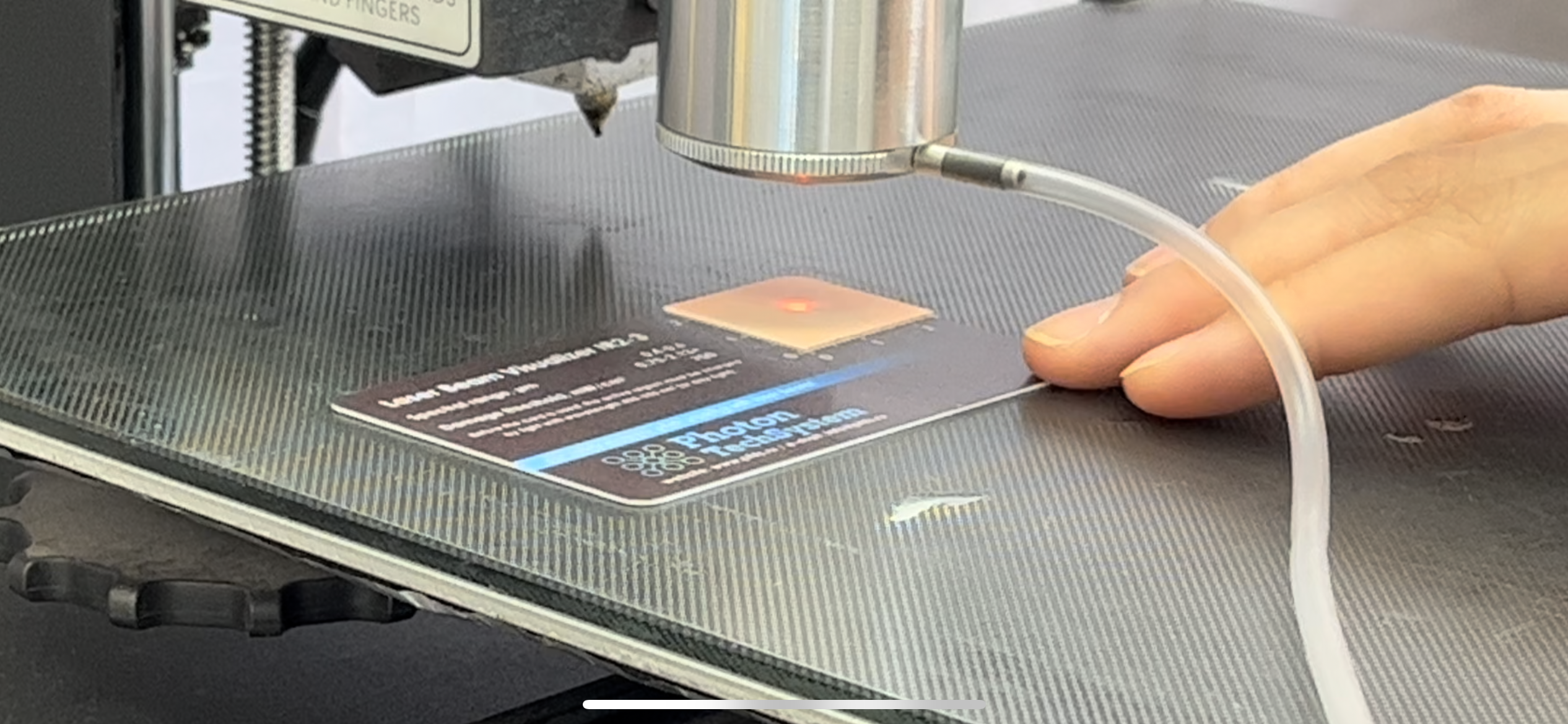
Figure 6 – Demonstration of the laser beam “Raycus RFL-P50QB”
A) IR 1-3 for the spectral range 0.75-1.5 µm B) IR 2-3 for the spectral range 0.75-2.13 µm
On the IR 4-3 visualizer, the beam was displayed as a dot (Figure 7) since it is not included in the spectral range of 1.14-1.64 µm.
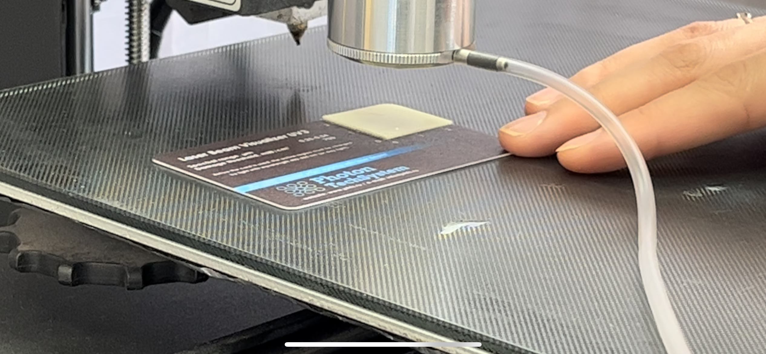
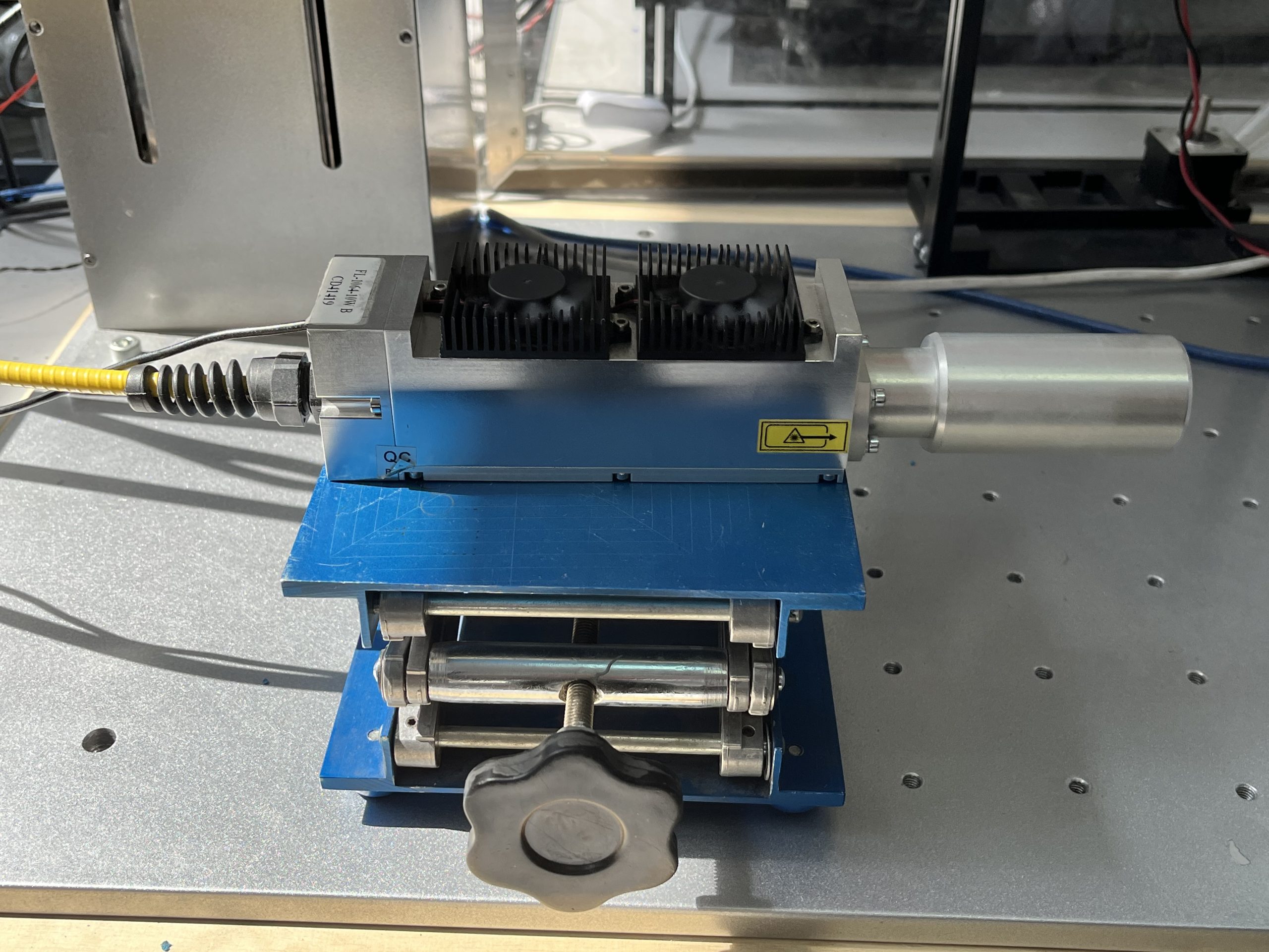
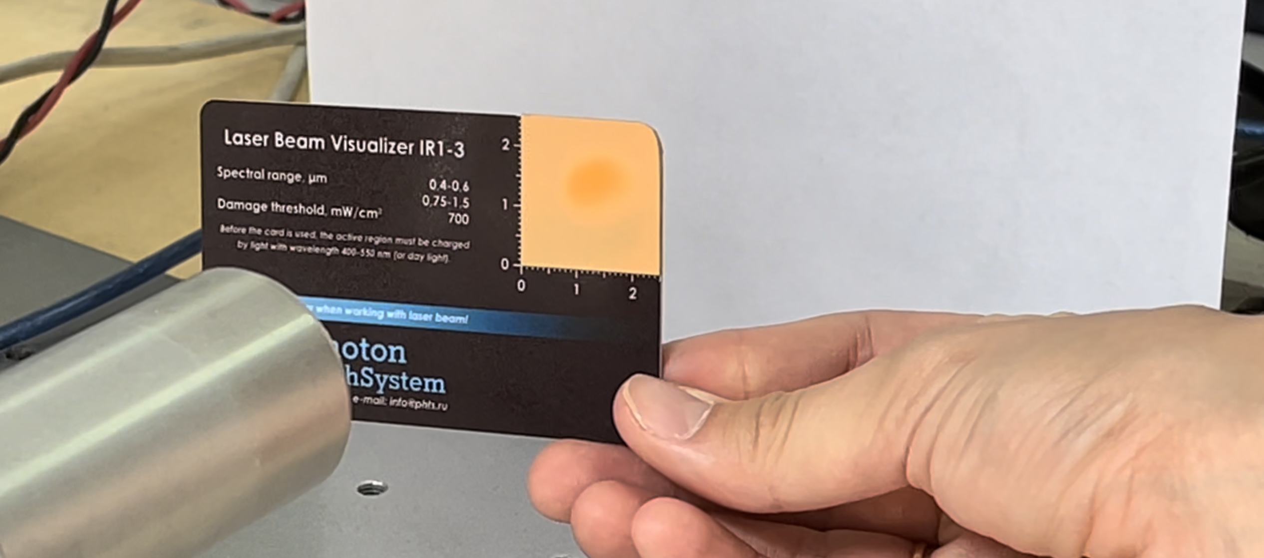
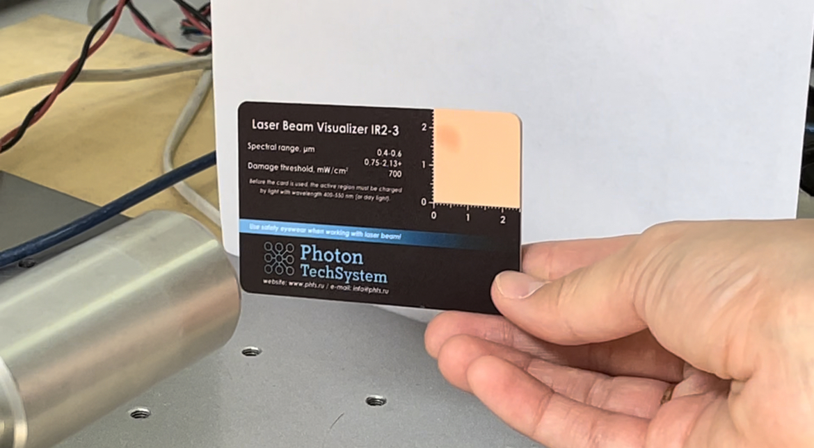
The third experiment was carried out with a FL-1064-10W marking laser with a wavelength of 1064 nm and an average power of 10 W (Figure 8). For indication, the IR 1-3 and IR 2-3 plates were best suited (Figures 9-10). The use of two other plates did not give any result.
As a result of the experiments, the operation of plates for visualizing the laser beam of three different lasers was demonstrated.