Detailed guidance of how to add 30 / 50 watt fiber laser emitter (Raycus) on 3D printer / CNC router.
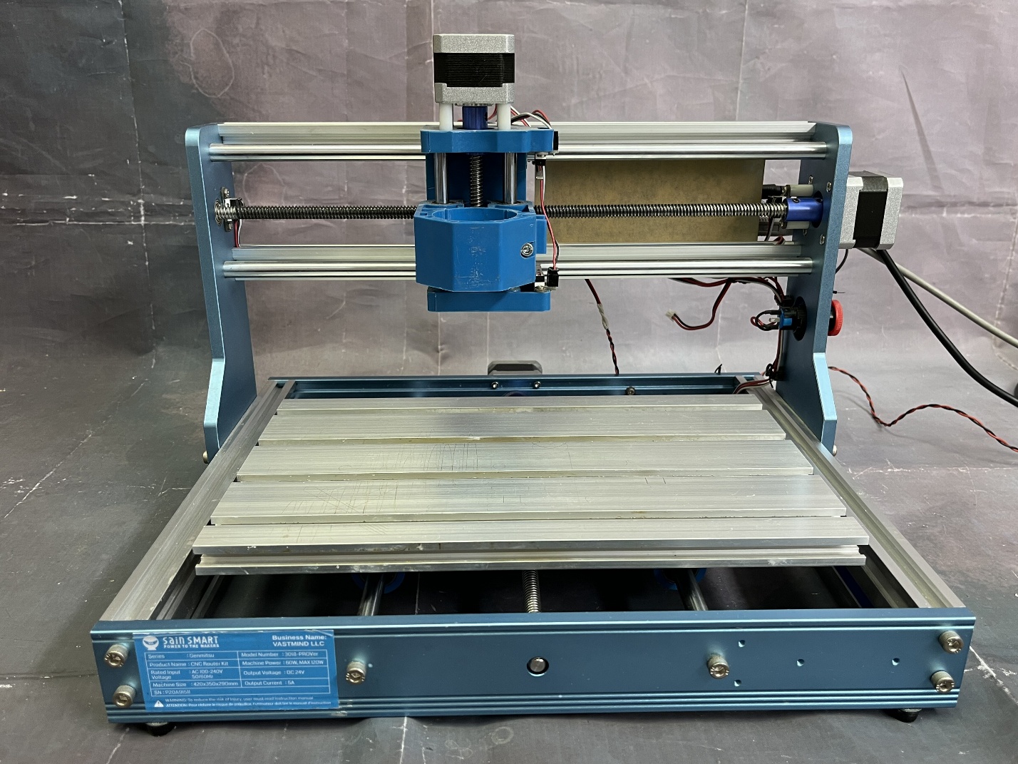
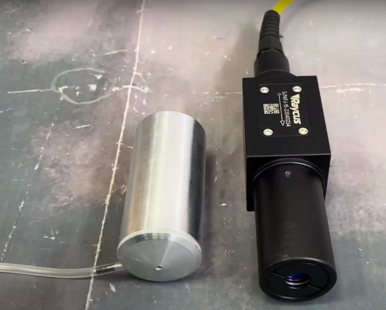
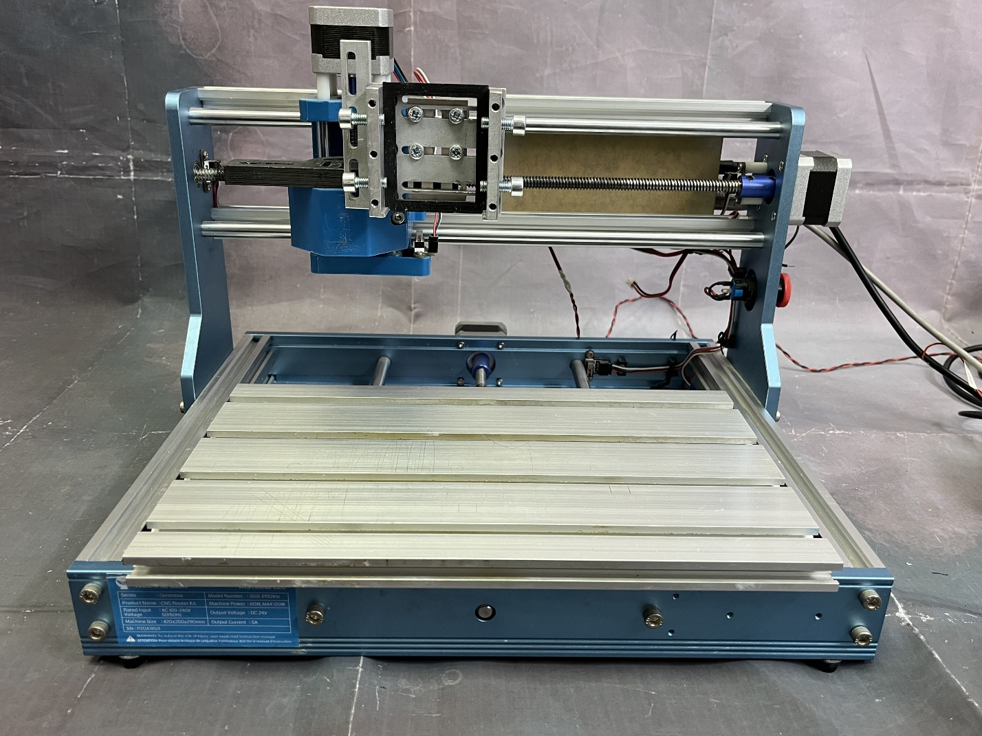
To complete the task, a desktop CNC milling machine ” Genmitsu” was used. 3018- PROVer “. This machine, in addition to working with milling, allows you to work with a laser. It is equipped with three axes, a maximum travel speed of 1500 mm/m, a working field of 300 mm by 180 mm (Figure 1) and subsequently a Raycus pulsed fiber laser mounted on it. RFL – P 50 QB » power 50 W and wavelength 1060-1085 nm (Figure 2). There is also a detachable laser attachment with a converging lens with a focal length of 30 mm . To prevent engraving products from getting on the lens, the nozzle is equipped with a nozzle for supplying gas to the laser area. The laser and the tank are controlled using the LightBurn program.
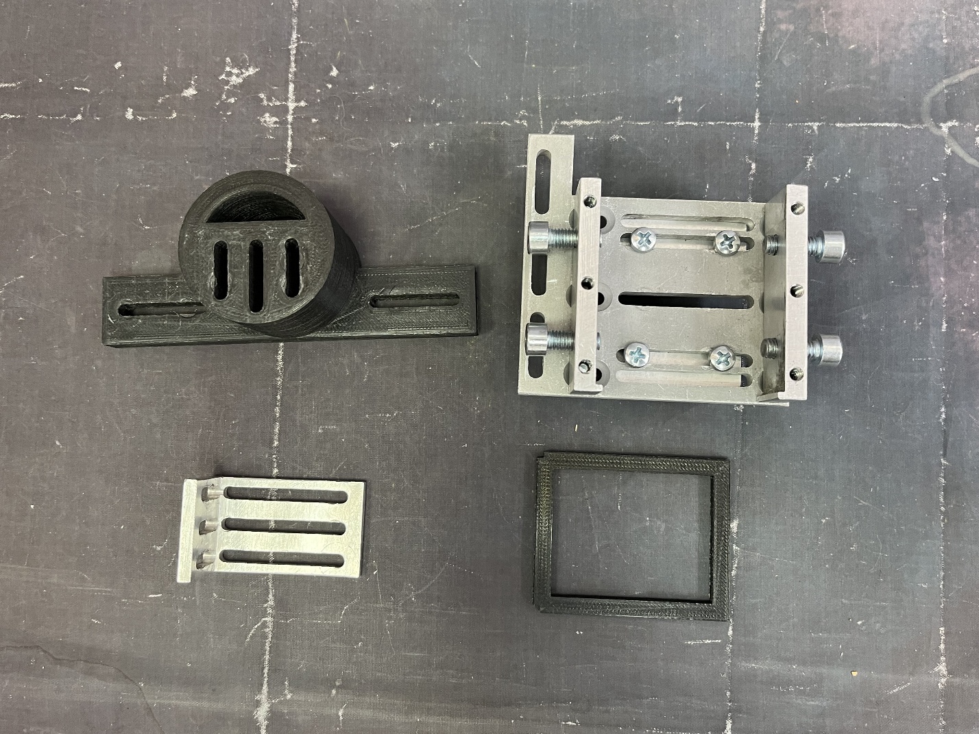
To accomplish the task, universal fasteners were used; plastic fasteners printed on a 3D printer , installed in the place where the spindle is attached. Both fasteners will be connected together using an L – shaped fastener. An additional plastic spacer was used in the universal mount for a more secure mounting of the laser . The fiber laser device does not turn off the ability to control the laser using a PWM signal, so a special adapter was used to control it , with which the laser is connected to the control board of the machine.
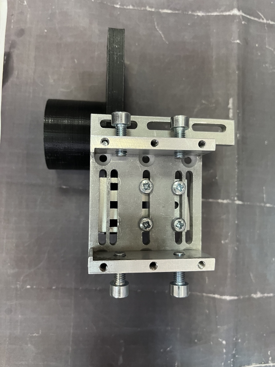
As a result of the first assembly stage, the result shown in Figure 4 was obtained.
At the next stage, the assembled mount is fixed on the installation. First of all, it is necessary to install a plastic stand for a more correct position of the laser, and also to prevent damage to it by the mounts. The appearance of the installed mount with a plastic stand is shown in Figure 5
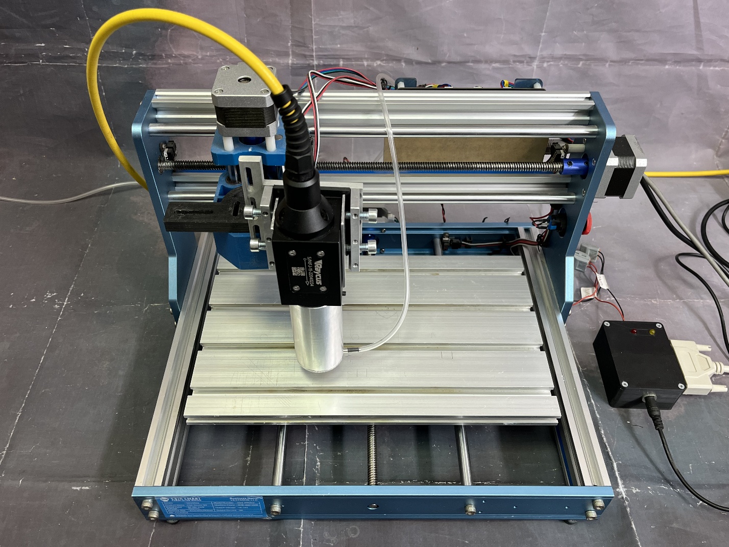
At the third and final stage, the laser itself is fixed with its nozzle already put on it and it is connected. To protect the laser body from damage from the side, metal plates were placed at the points of contact with the fasteners. To properly set up the laser, it is recommended to use a level or measuring angle to ensure that the laser is level. The result of the installation is shown in Figure 6.
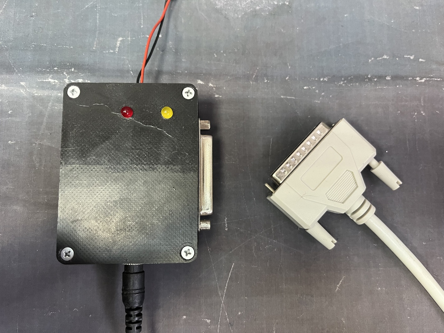
After installation, it is necessary to connect the laser to the machine using an adapter, which is shown in Figure 7. The adapter is equipped with two wires that receive a PWM signal from the machine control board. The laser is connected to the adapter via a DB 25 connector. The adapter also requires a separate DC 12 V power supply.
When the adapter is connected to the mains, the red indicator light emitting diode lights up, indicating that the adapter does not have a connection to the laser. After power is supplied to the laser, it goes out, which means that the laser is connected to the adapter.
Fiber laser upgrade package: PWM control box + focusing system
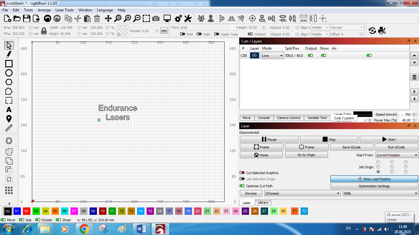
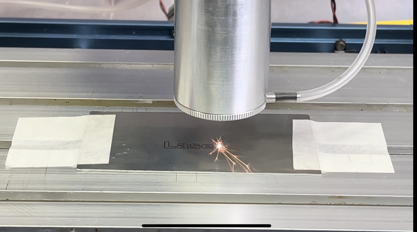
The second task is to check the quality of the work of the fiber laser installed by us. For this, an engraving was made on a stainless steel plate. Since the machine is three-axis, the program LightBurn (figure 8) we can adjust the height of the laser to match its focal length. In the process of making several experiments, it was found that for each speed a different power should be set. So for a lower speed, 20-25% will be enough, for a higher 30-50%. Optimal parameters for engraving: speed 700 mm/m, laser power 40%. In our case, we chose the speed so that the corresponding power does not burn through the plate much. Since the machine has a movable table on which the plate is located, there is a need to fix the plate on the working area of the machine in order to avoid its shift during the engraving process. The work process is shown in Figure 9.
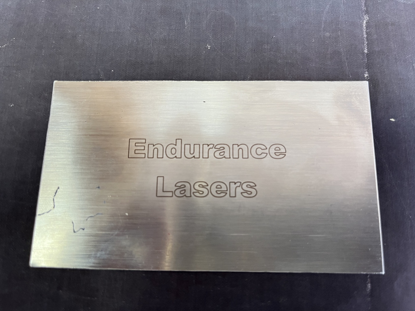
At the output of the process, we got the following result (Figure 10):
The work carried out shows that the Raycus fiber laser RFL – P 50 QB » can be used on a CNC machine.