Statement of the problem: it is necessary to install a Raycus 50W fiber laser on a 3D printer and check its performance.
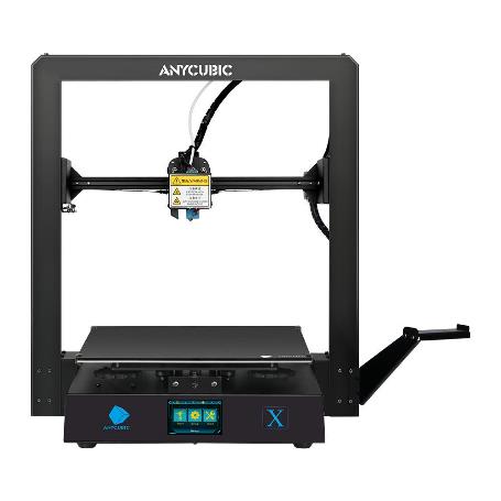
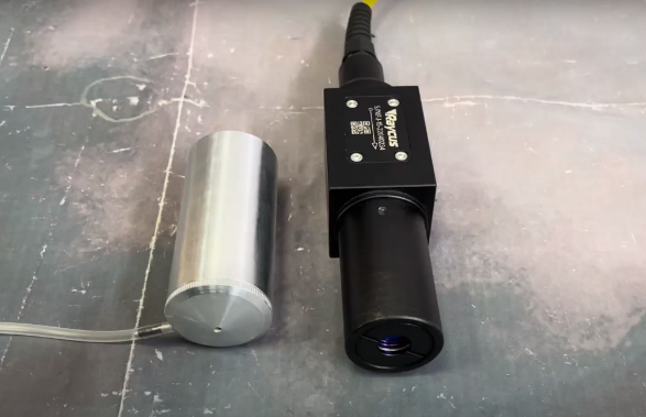
To complete the task used: Anycubic 3D printer Mega X. The printer print speed is 20-100 mm/s (recommended 60 mm/s), the working field is 300 by 300 mm (Figure 1) and subsequently the Raycus pulsed fiber laser installed on it RFL – P 50 QB » power 50 W and wavelength 1060-1085 nm (Figure 2). There is also a detachable laser attachment with a converging lens with a focal length of 30 mm . To prevent engraving products from getting on the lens, the nozzle is equipped with a nozzle for supplying gas to the laser area. The laser and the tank are controlled using the LightBurn program .
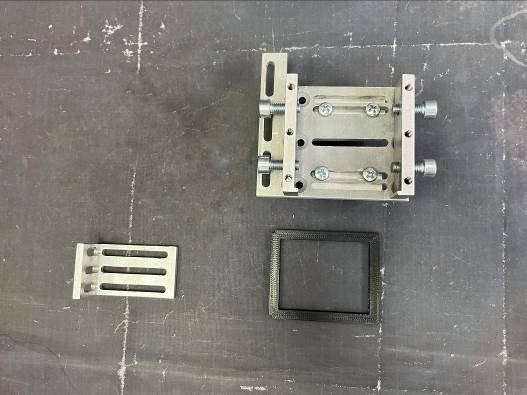
To accomplish the task, universal fasteners were used. The extruder and universal fastener will be connected together using an L – shaped fastener (Figure 3). An additional plastic spacer was used in the universal mount for a more secure mounting of the laser .
As a result of the first assembly stage, the result shown in Figure 4 was obtained.
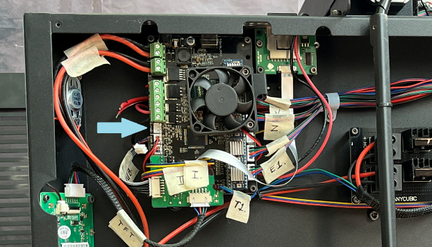
The laser is controlled using a PWM signal, the connection is made to the control board of the 3D printer in the connector for connecting the fan blowing the printed model during 3D printing marked “ FAN 0” (indicated by an arrow in Figure 5). Since the chamber is located inside the printer, for ease of control, the wires leading to the fan were brought out and provided with terminal connectors.
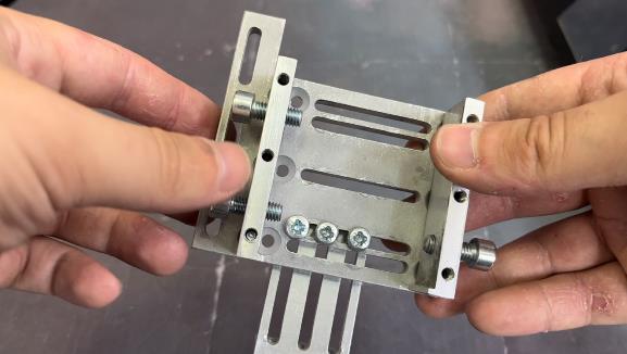
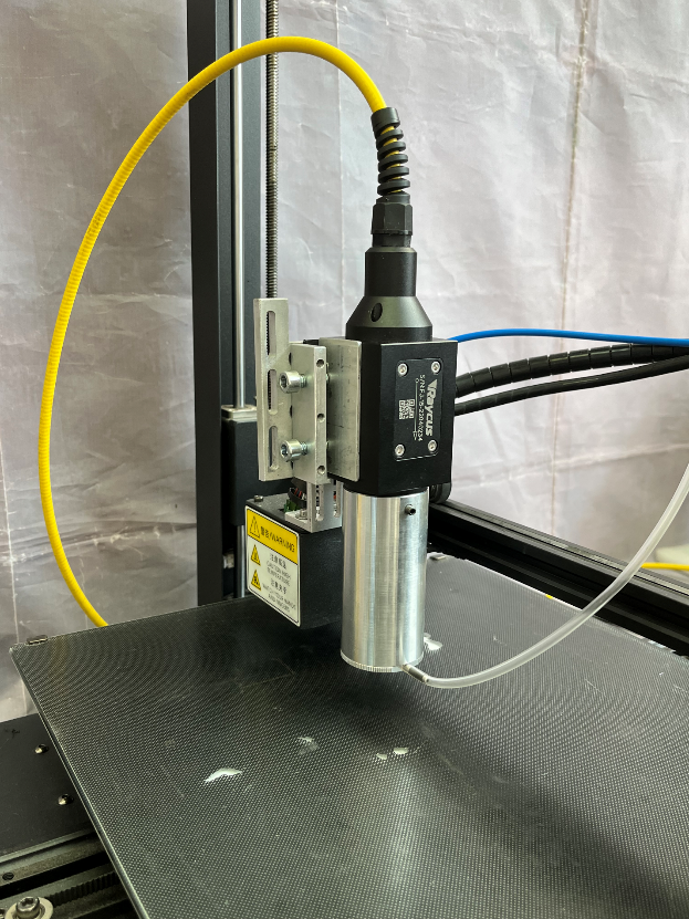
At the next stage, the assembled mount is fixed on the installation. First of all, you need to fix the mount on the extruder using the L-shaped fastener. After that, the laser is fixed in the mount. In order to prevent damage to the mounts, a plastic spacer and metal plates are installed inside. To properly set up the laser, it is recommended to use a level or measuring angle to ensure that the laser is level. The appearance of the installed mount with a laser fixed in it is shown in Figure 6
The fiber laser device does not turn off the ability to control the laser using a PWM signal, so a special adapter was used for control, which allows you to control the laser using a PWM signal.
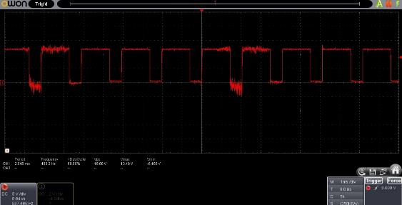
Before connecting, the PWM signal was checked on an oscilloscope. According to the measurement results, it was found that the printer, when the fan is turned on at maximum speed, produces a PWM signal with a duty cycle of 70%, a voltage of 12 V and a frequency of 500 Hz
The adapter uses a PWM signal to connect the laser with a frequency of 1000Hz, according to the measured PWM signal, it is not possible to turn on the laser at 100% power. To correct this, a dynamic PWM signal regulator was used. With this connection scheme, the printer’s PWM output is always set to 100% power, and the laser power is controlled using a dynamic PWM signal controller.
To get a PWM output signal with a duty cycle of 100%, you need to use a capacitor that is connected in parallel to the input of the regulator. When using a 1uF capacitor, the minimum voltage when the printer fan was turned on was 5V (Figure 8).
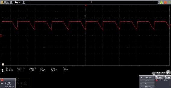
The minimum input PWM signal voltage at the input of the regulator is 3.5 V. Therefore, the PWM signal shown in Figure 8 will be perceived by the regulator as a PWM signal with a duty cycle of 100%
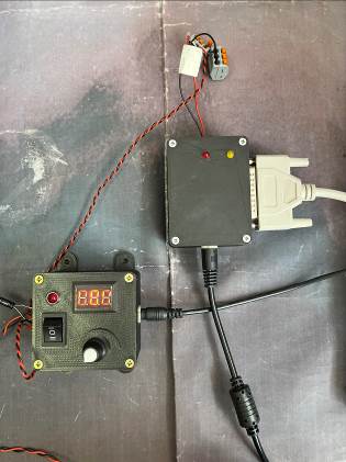
The connection scheme is as follows: the wires going to the printer fan are connected to the dynamic PWM signal controller ( IN 2 input terminals), the adapter is connected to the controller output terminals. The laser is connected to the adapter via a DB 25 connector. The adapter and the controller also require a separate DC 12 V power supply.
When the adapter is connected to the mains, the red indicator light emitting diode lights up, indicating that the adapter does not have a connection to the laser. After power is supplied to the laser, it goes out, which means that the laser is connected to the adapter.
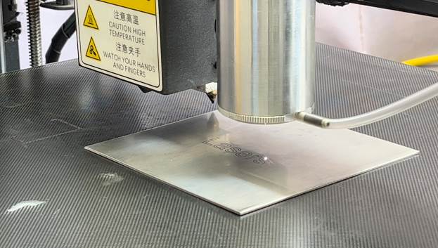
The second task is to check the quality of the work of the fiber laser installed by us. For this, an engraving was made on a stainless steel plate. Because the machine is three-axis, we can adjust the laser’s lift height in LightBurn to match its focal length. In the process of making several experiments, it was found that for each speed a different power should be set. Optimal parameters for engraving: speed 270 mm/m, laser power 30% . In our case, we chose the speed so that the corresponding power does not burn through the plate much. The work process is shown in Figure 9.
Technically, the printer has the ability to move the laser at a higher speed, but due to the specific design of the extruder carriage, vibrations occur at high speeds, which can affect the quality of the engraving.
At the output of the process, we got the following result (Figure 11):
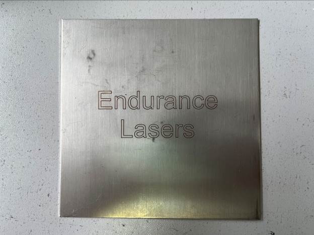
The work carried out shows that the Raycus fiber laser RFL – P 50 QB » can be used on a 3D printer for engraving.