A detailed post of how to replace a laser diode and setup voltage and current on DC/DC converter.
All you need to know how to fix your laser.
Valid for Endurance 10 watt / 10 watt Delux / 10 watt PLUS / 10 watt PRO’s
10 watt basic "Invincible" laser attachment for laser engraving and laser cutting
10 watt (10000 mw) PLUS laser cutting attachment (includes air nozzle and air compressor)
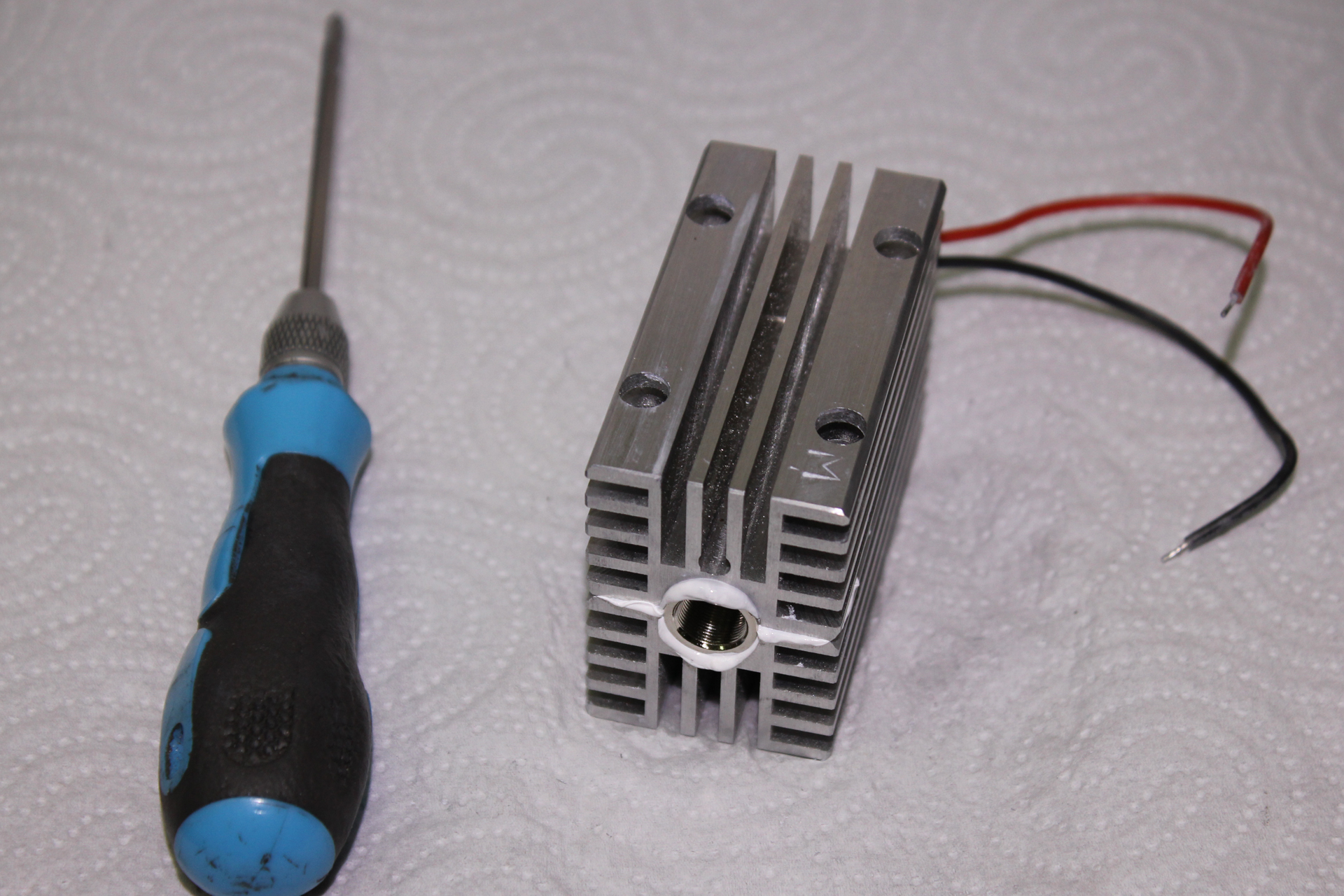
Remove the braid and remove the heat shrinkage from the wires to which the laser diode is connected (these 2 wires are thicker than the others).

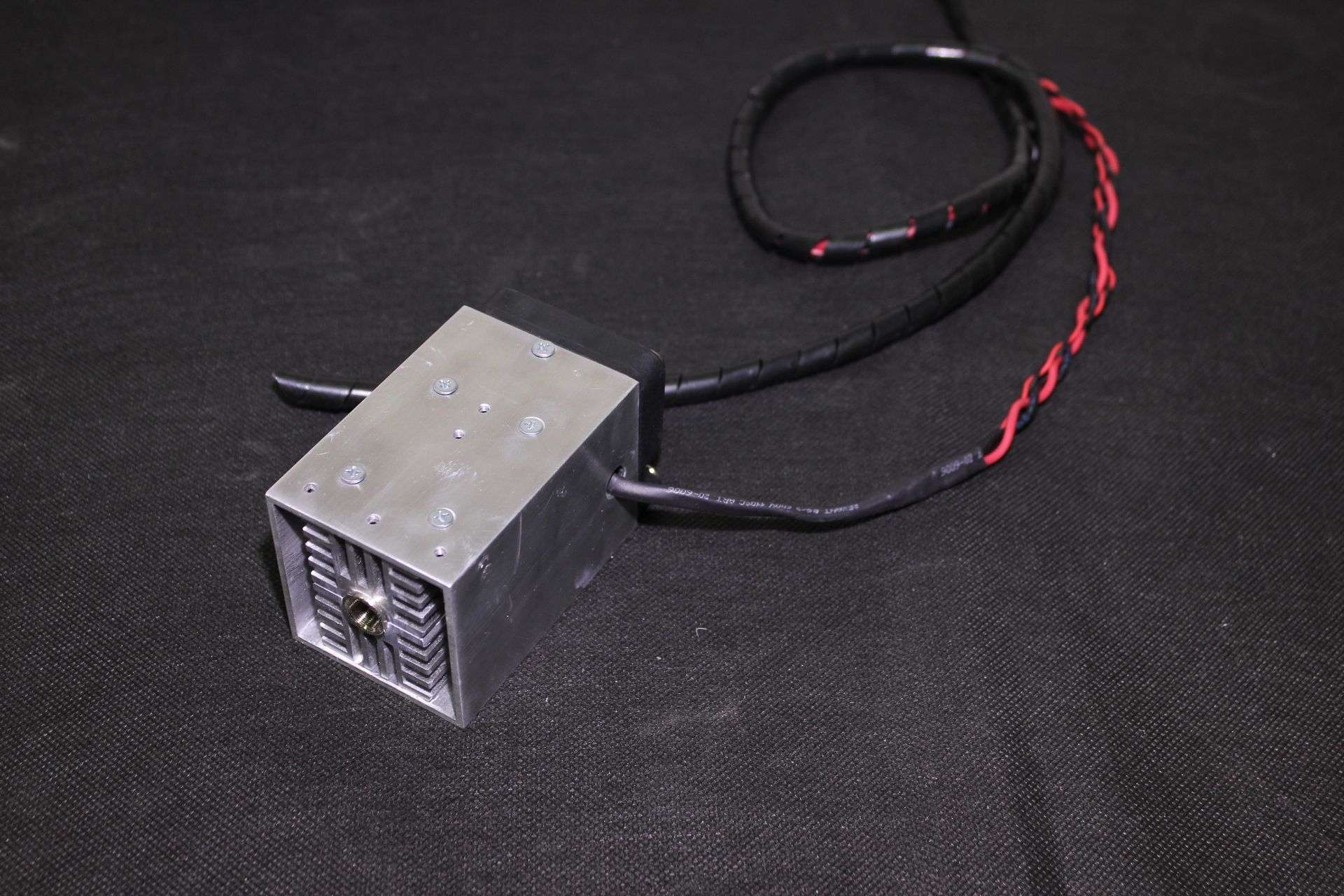
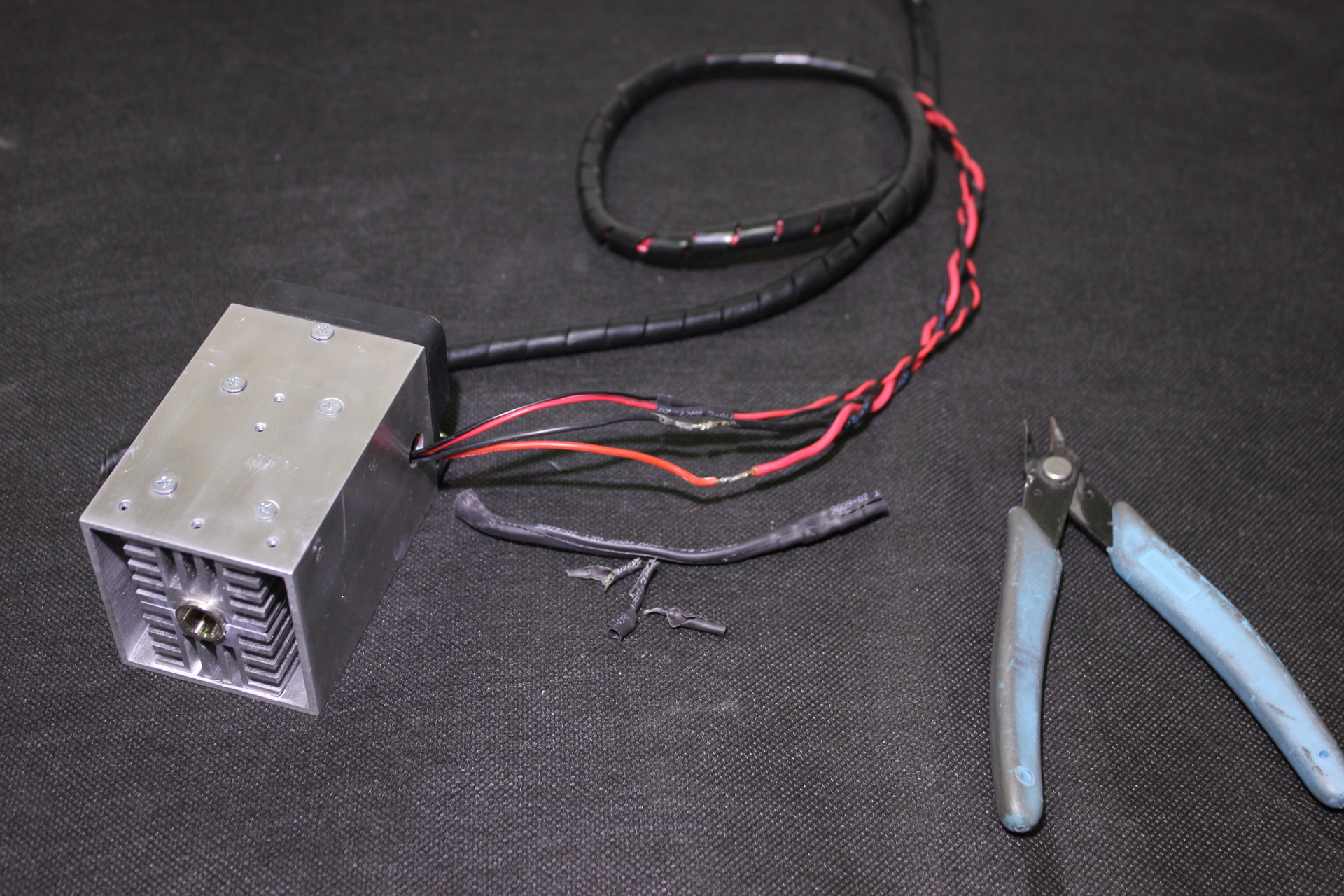
We unsolder the wires to which the laser diode is soldered.

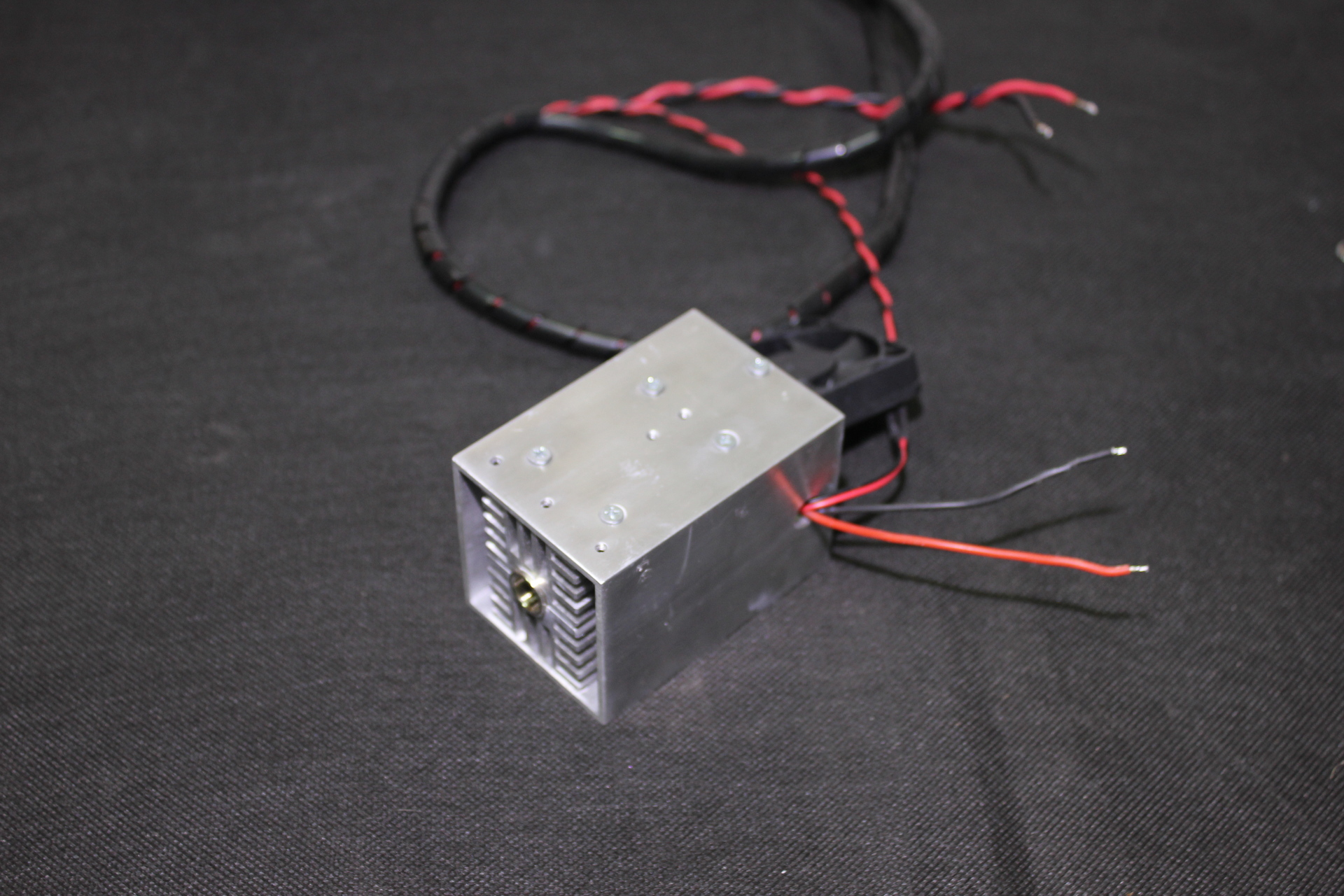
Unscrew the screws holding the fan and remove it from the laser housing.
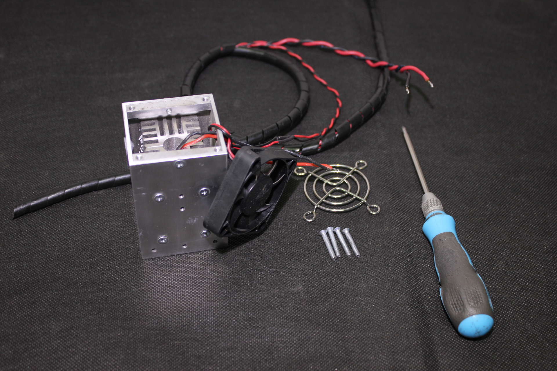
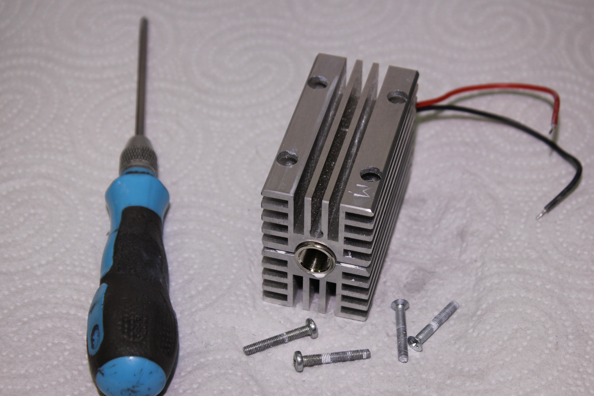
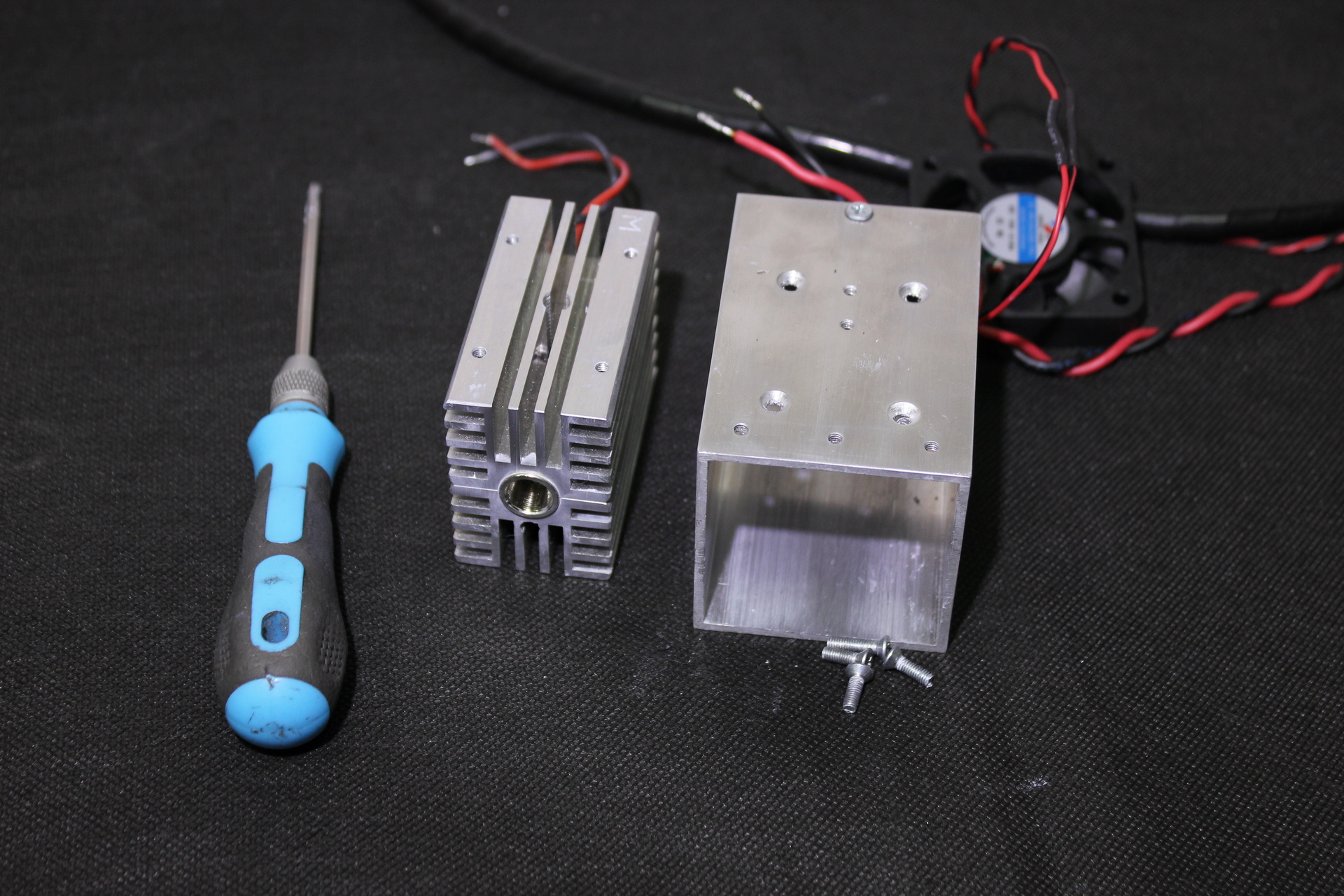
Unscrew 4 screws on the laser housing and take out the radiator with the laser diode.
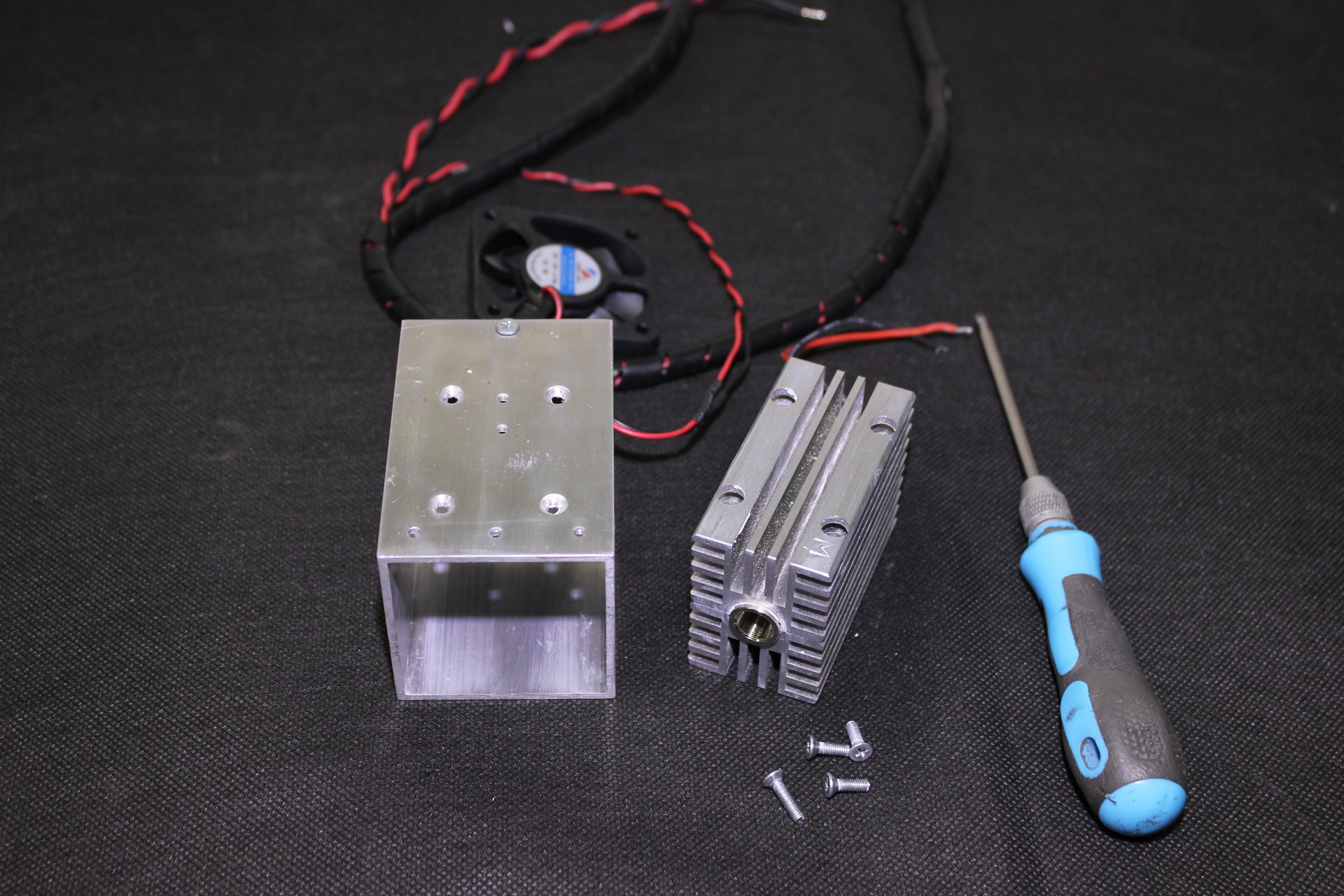
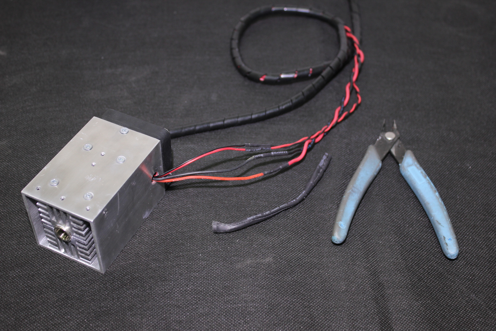
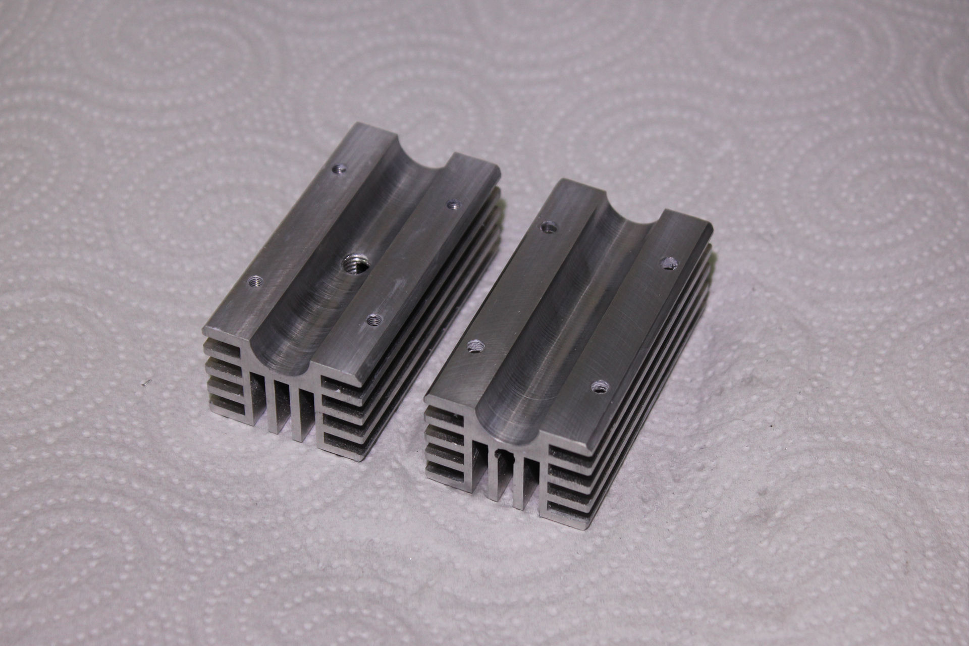
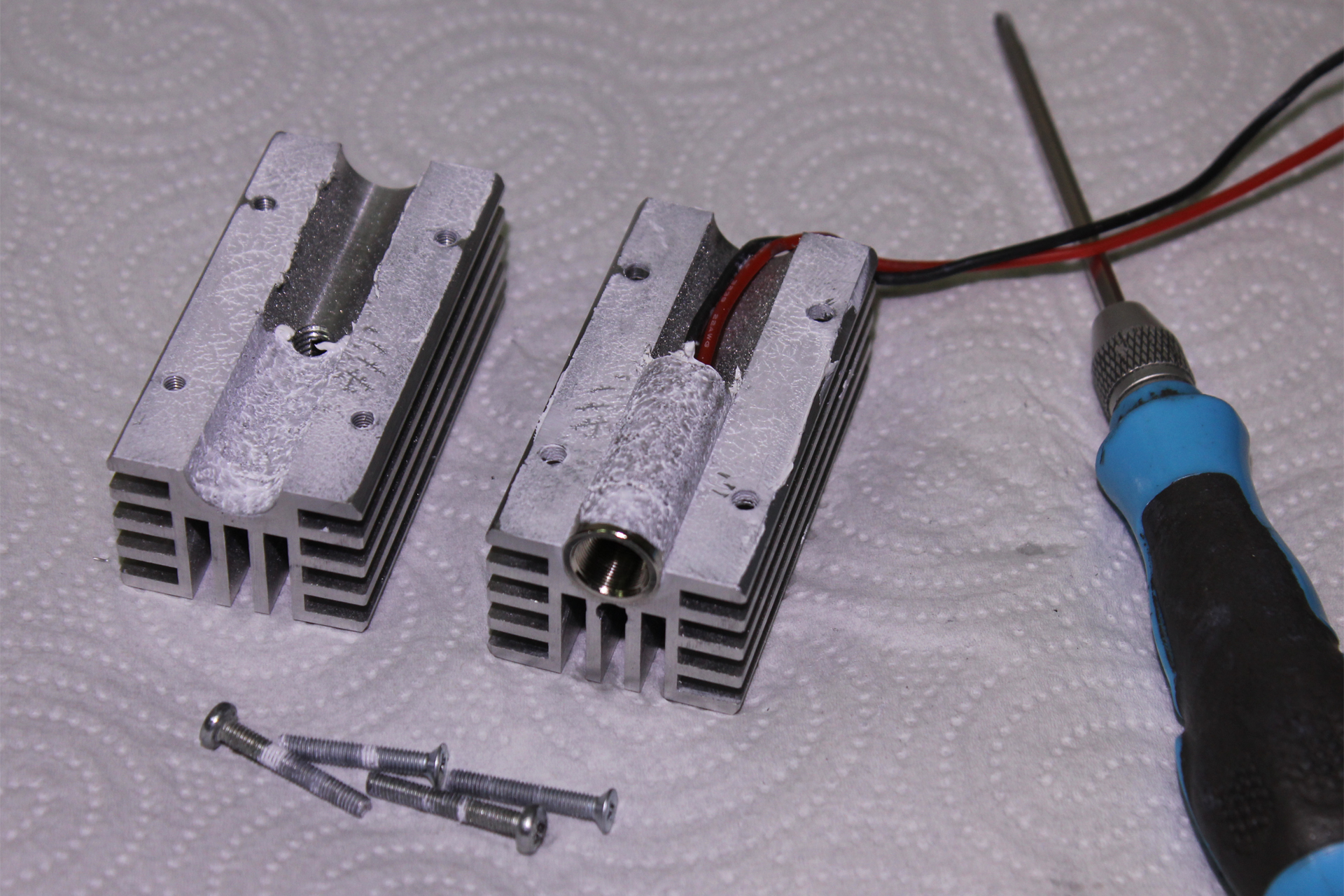
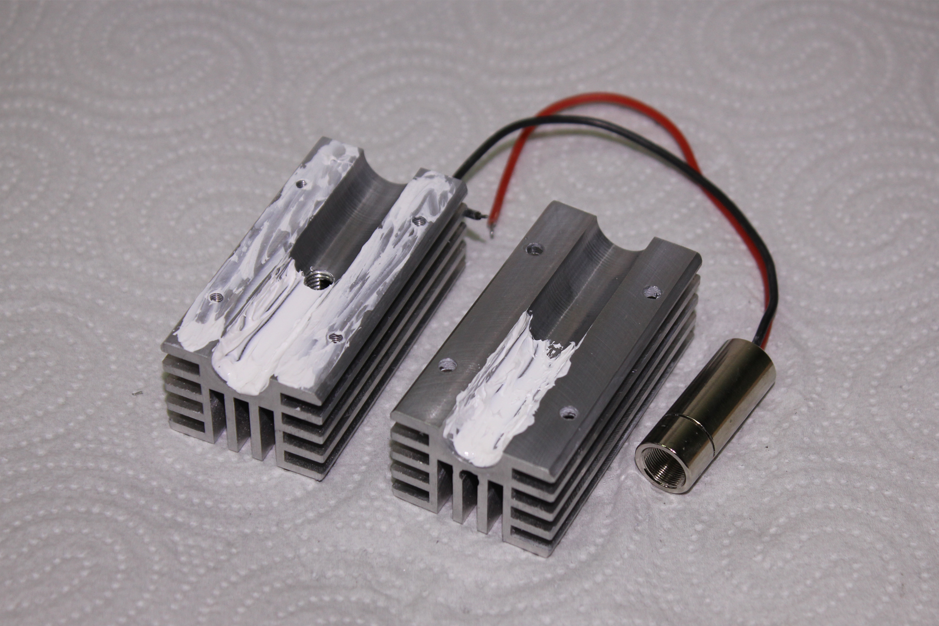
The radiator consists of two parts connected by screws. We unscrew the screws and disassemble the radiator.
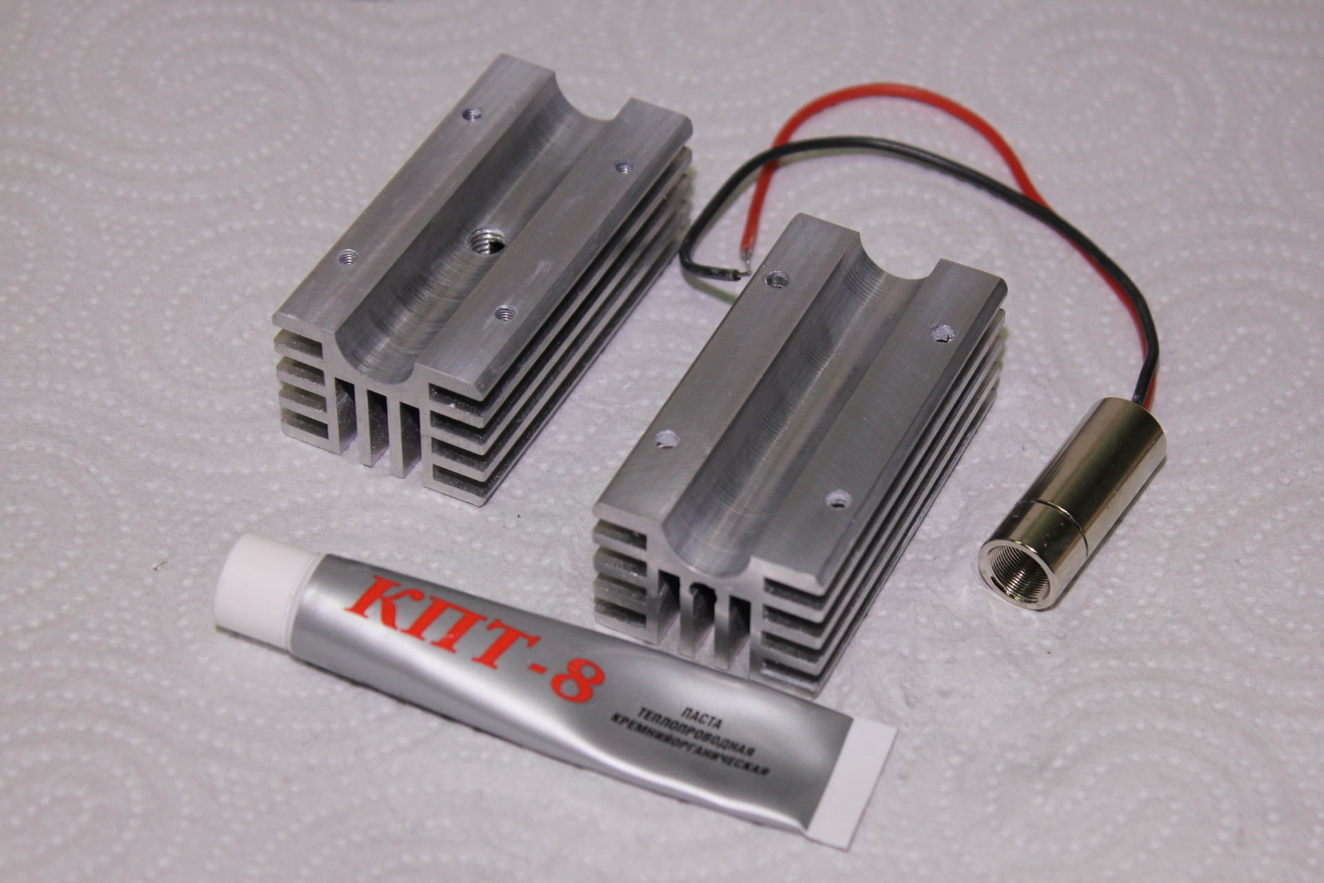
We take out the faulty laser diode from the radiator and clean the old thermal paste from the radiator.
Apply new thermal grease to the inside of the radiator and install a new laser diode in the radiator.
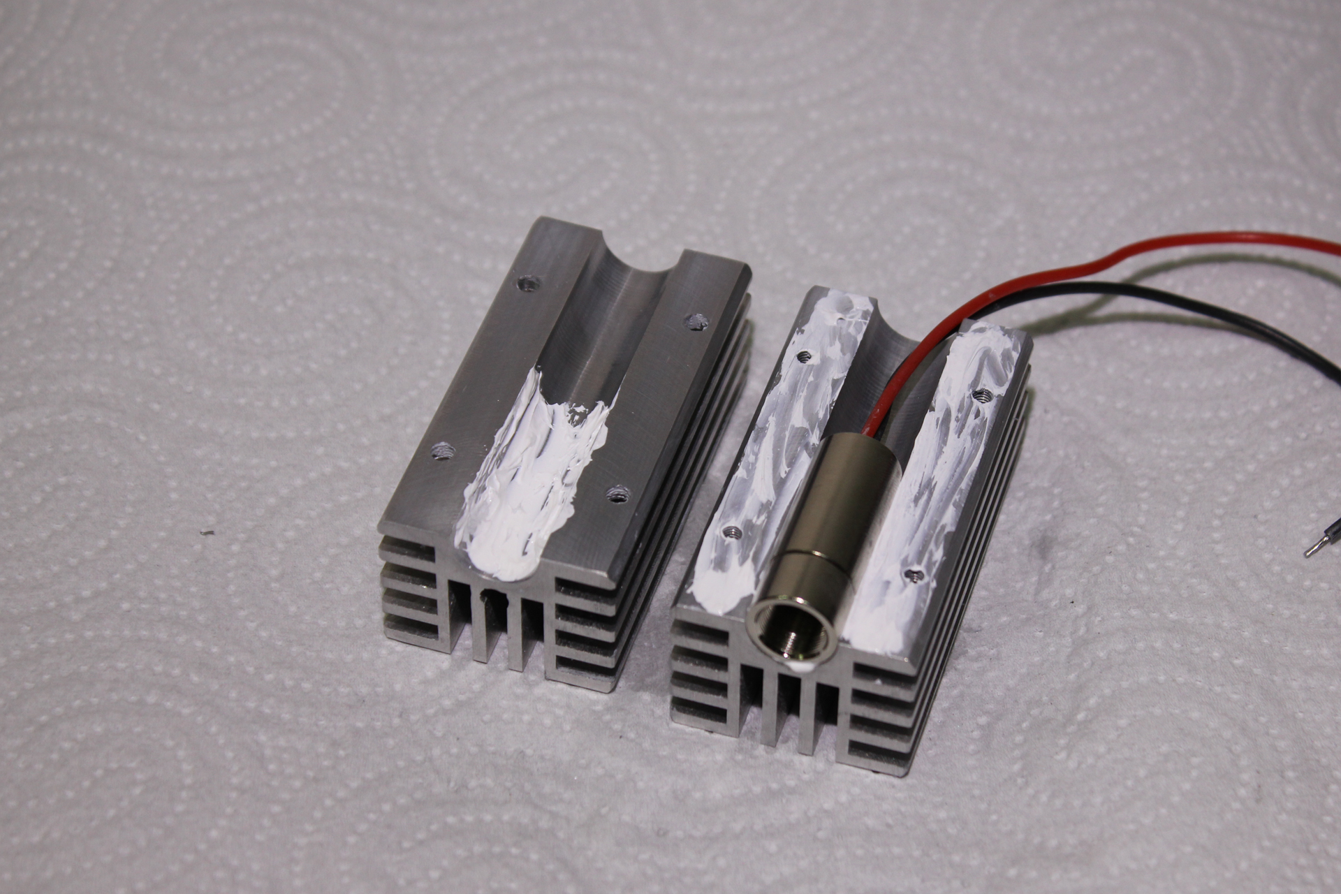
We collect the radiator. We screw it up with screws. Excess thermal paste with a napkin. In hard-to-reach places, you can use cotton swabs.
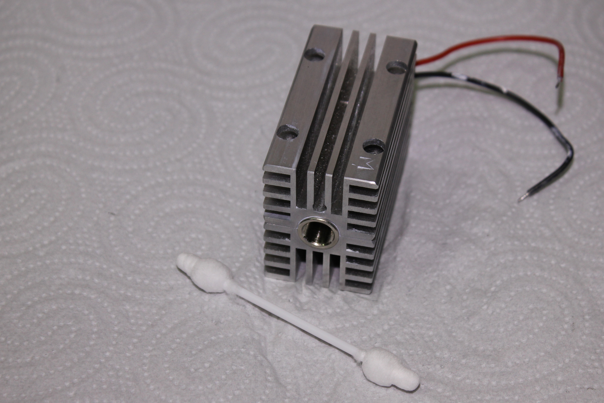
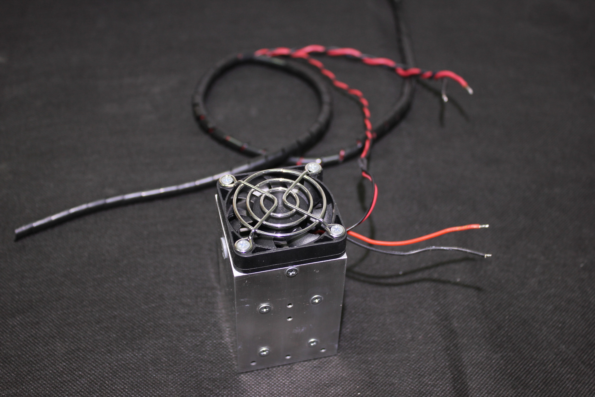
We put the radiator back into the case. We screw it on. We bring the wires from the laser diode to the outside of the case. We screw on the fan.

We put a heat-shrink tube on the wires. This can be done at the very end, after the final adjustment of the laser, but then you will have to re-solder one of the wires.
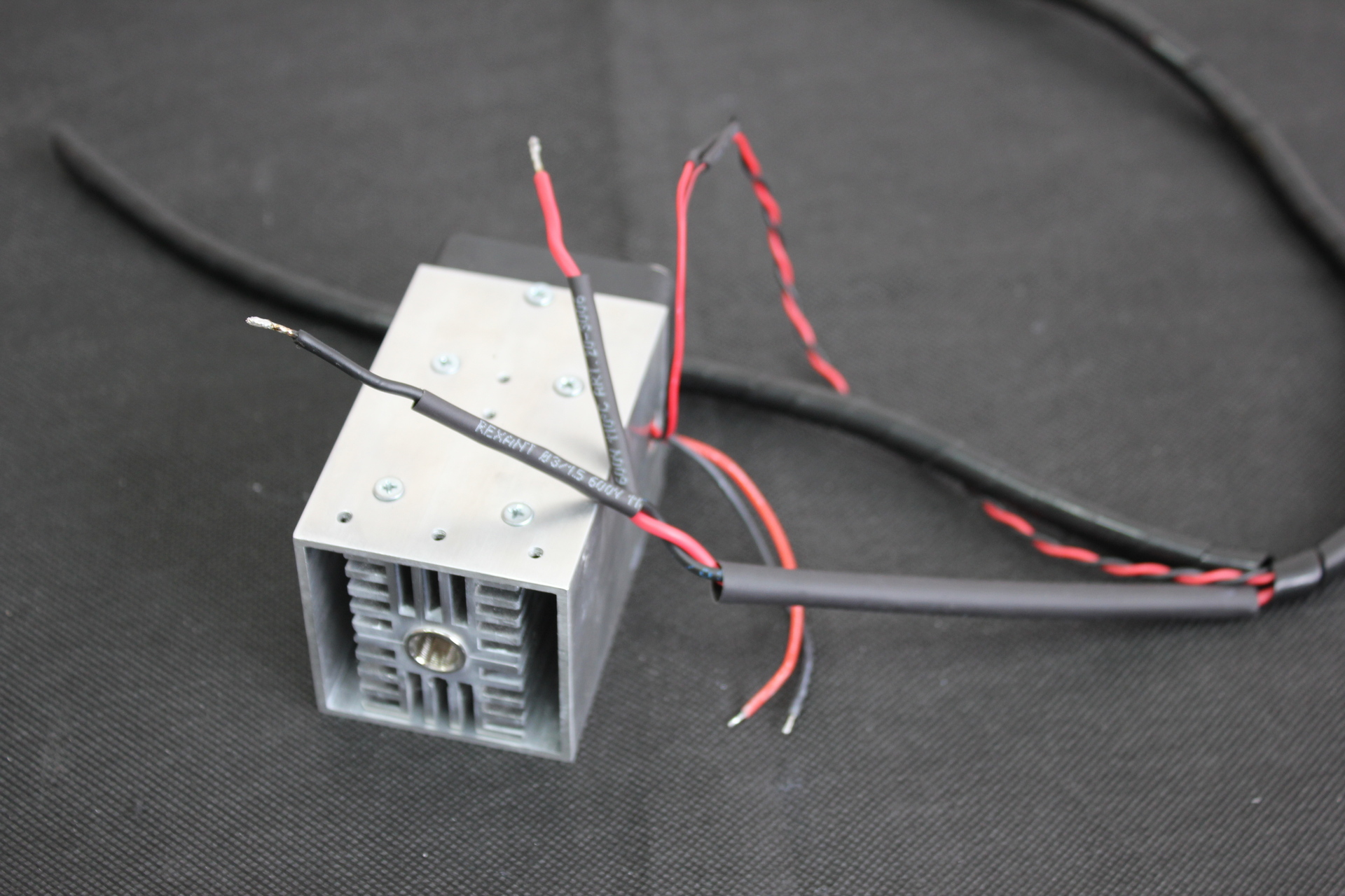
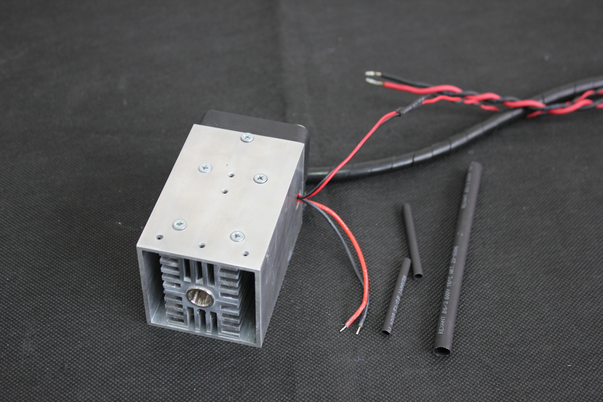
We solder the negative (black) wire from the laser diode to a similar wire from the laser control unit. Do not touch the positive (red) wire yet.

Unscrew the screws securing the cover to the laser control unit.
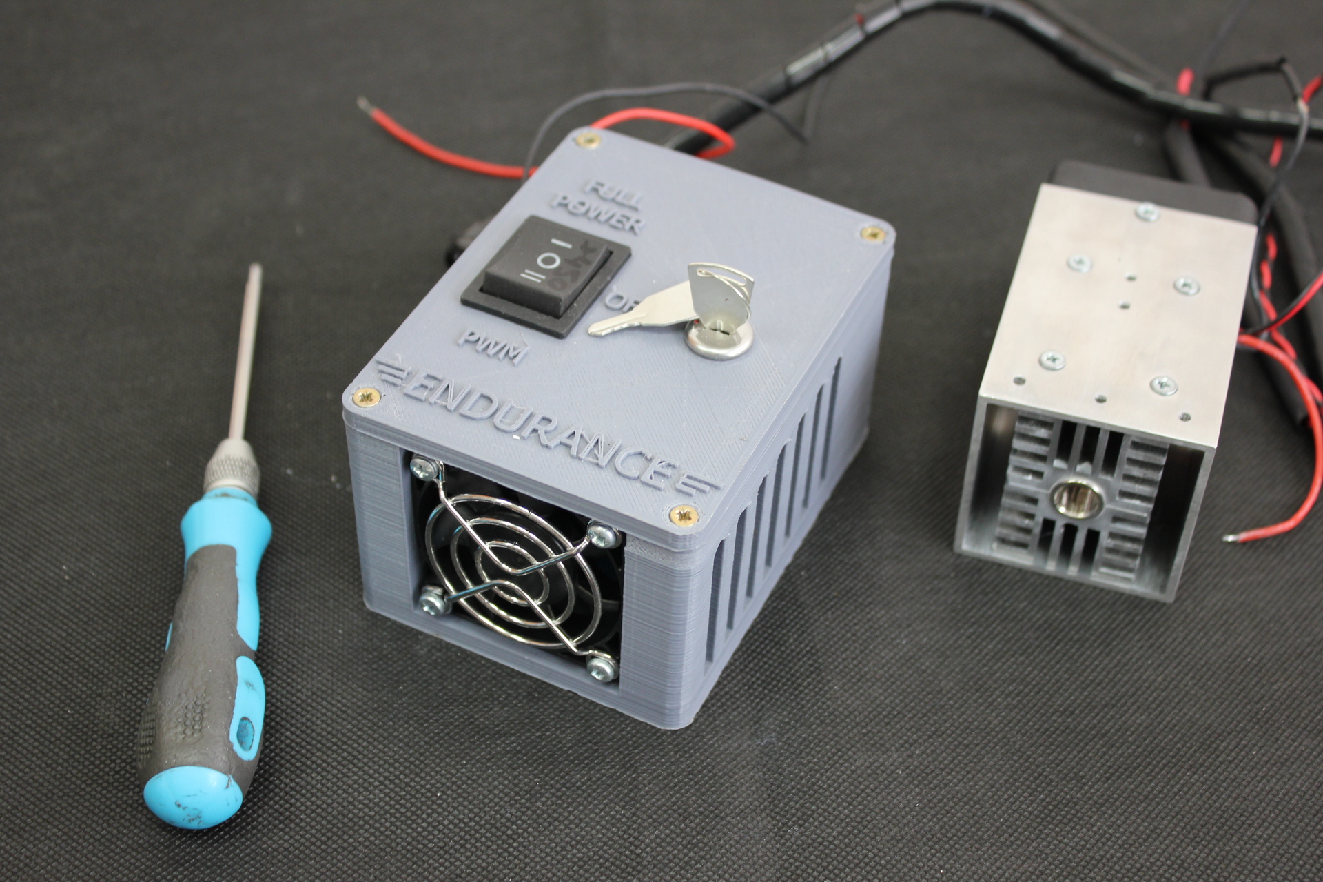
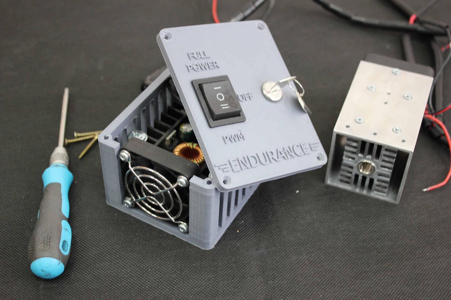
The laser control units use 2 types of DC-DC modules.

1 – Input voltage from power supply “+”
2 – Input voltage from the power supply “-”
3 – Output voltage to laser “+”
4 – Output voltage to laser “-”
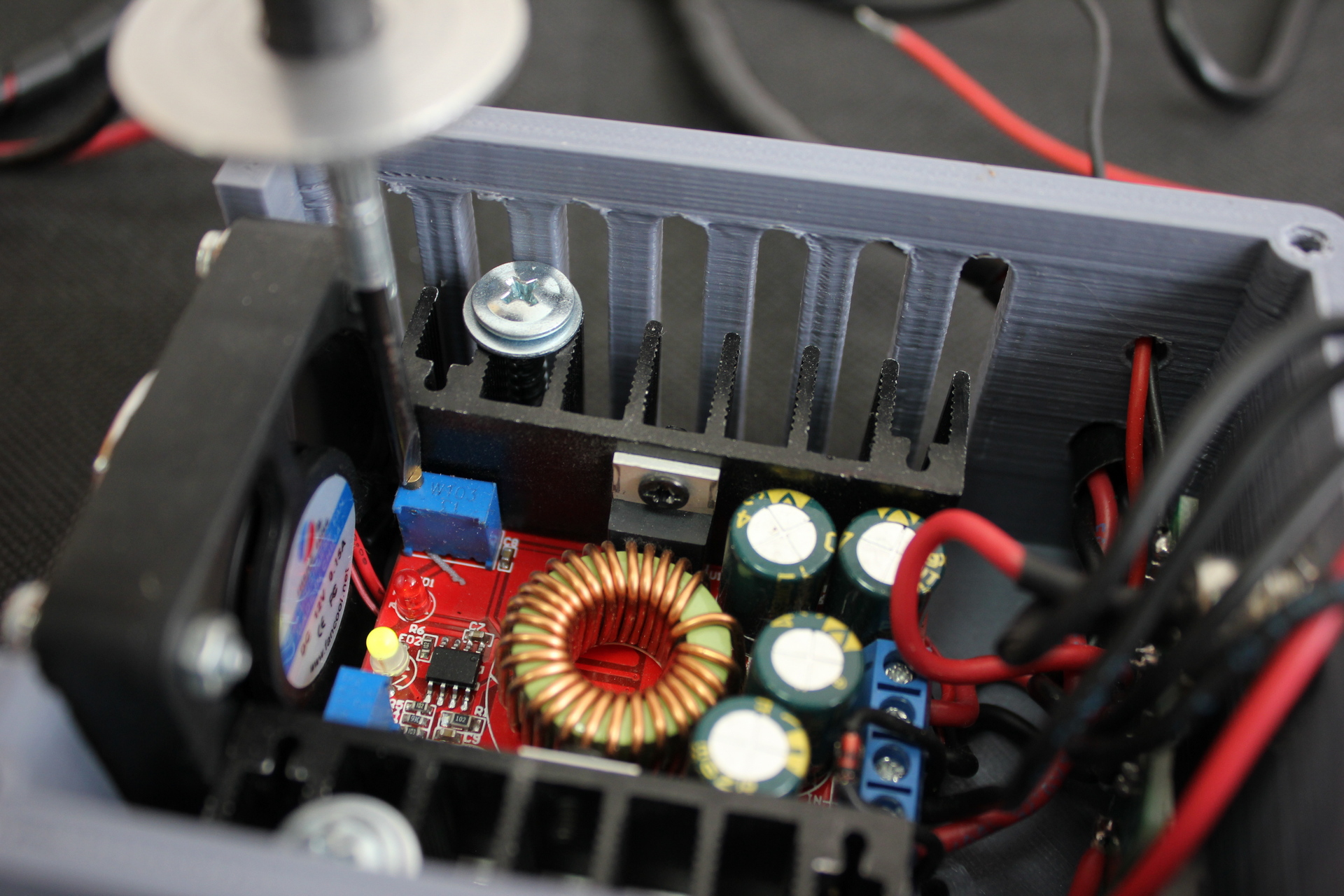
5 – Voltage regulator. Counterclockwise rotation – increase, clockwise rotation – decrease.
6 – Current limiter. Clockwise rotation – increase, counterclockwise rotation – decrease.

1 – Input voltage from power supply “+”
2 – Input voltage from the power supply “-”
3 – Output voltage to laser “+”
4 – Output voltage to laser “-”
5 – Voltage regulator. Clockwise rotation – increase, counterclockwise rotation – decrease.
6 – Current limiter. Clockwise rotation – increase, counterclockwise rotation – decrease.
Features:
– Fixed turn lamp current is 0.1 times the current value
( Used to identify whether the battery is fully charged When charging).
– Made from a dedicated benchmark IC and high-precision current sensing resistor, proving a more stable constant current,
(when 20°C to 100°C constant current 1A, temperature drift less than 1%). Particularly suitable for LED.
– High output current, the max output current can reach 8A.
– Four high-frequency capacitance, can lower output ripple, enhance the work stabilization.
– Double heat sink design. MOS Schottky diode independent heat sink,
which heat dissipation is good, and won’t affect each other.
– Using large size Sendust Core and double pure copper wiring, improve working efficiency, reduce fever.
– 3296 multiturn potentiometer, high accuracy voltage and current regulation, good stability.
– Double color lamp, working condition be clear at a glance
– Voltage and current are adjustable, which effect is good.
Parameters:
– Module Properties: Non-isolated step-down constant current, constant voltage module (CC CV) charging module
– Input Voltage: DC 7-32V
– Output Voltage: (1) DC 1.2-28V continuously adjustable. (2) Fixed output:Choose between 0.8v-28v
– Output Current: 8A (when power tube’s temperature exceeds 65 degrees, please add cooling fan)
– Constant Current Range: 0.2-8A (Adjustable)
– Turn Lamp Current: Constant current value * (0.1), turn the lamp current and constant value linkage,
such as constant current value is 3A, turn the lamp current is set to a constant current is 0.1 times (0.1 * 3A = 0.3A)
– Lowest Pressure: 1V
– Output Power: Maximum power is about 200W
– Conversion Efficiency: Up to about 95%
– Operating Frequency: 300KHZ
– Output Ripple: 20M bandwidth
– Input 24V Output 12V 5A ripple around 50mV (Excluding noise)
– Output Short Circuit Protection: Yes, constant current
– Input Reverse Polarity Protection: None
– Output Prevent Backflow: None
– Wiring: Terminal
– No-Load Current: Typical 20mA (24V switch 12V)
– Load Regulation: ± 1% (Constant)
– Voltage Regulation: ± 1%
– Dynamic Response Speed: 5% 200uS
– Potentiometer Adjustment Direction: clockwise (increase) , counterclockwise (decrease),
the potentiometer(CV) closed to the input voltage is used to regulate voltage,
the potentiometer(CC) closed to output voltage is used to regulate current (CC)
– Operating Temperature: Industrial grade (-40 °C to +85 °C) (please note the actual use of the power tube temperature ,
high-temperature heat strengthened)
– Indicator: dual color indicator, charging indicator light is red, the green light means fully charged (No load is green)
– Size: Approx. 65 x 47 x 23.5mm/2.56 x 1.85 x 0.93”
– Precision of Constant Current and Temperature: On the actual test, the module temperature from 25 degrees to 60 degrees,
the constant current value change is less than 5% (5A constant current value)
– Output Short Circuit Protection: Yes, Constant current (the current setting constant current value)
– Input Reverse Connect Protection: NO
– Output Prevent Reverse Fow: NO
– Wiring Method: Amphenol connector
(ABOUT DC/DC)
The control unit has numbers marked with a marker ranging from “+150” to “+450”. They can be applied to a button, a fan, or the case itself. Before starting laser tuning, they must be substituted into the formula
V = 5.1- (value of digits / 1000)
V is the maximum allowable voltage at the DC-DC output when the laser is operating in PWM mode. Exceeding this voltage may damage the DC-DC or laser diode. When the laser is off, the voltage may be slightly higher than when it is on. This is allowed.
The maximum allowable voltage at the DC-DC output in any mode is 5.1V.
Testing DC/DC

In our case, the numbers are “+450”. We substitute them into the formula
V=5.1-(450/1000)=4.65В
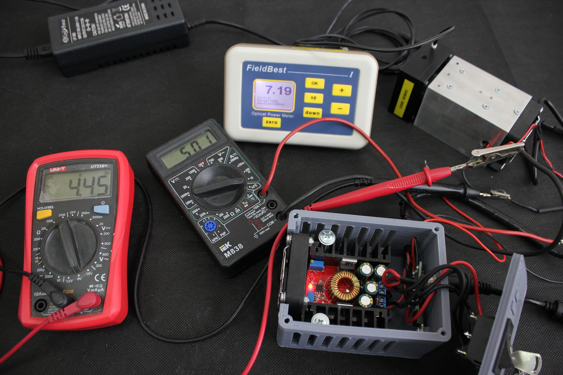
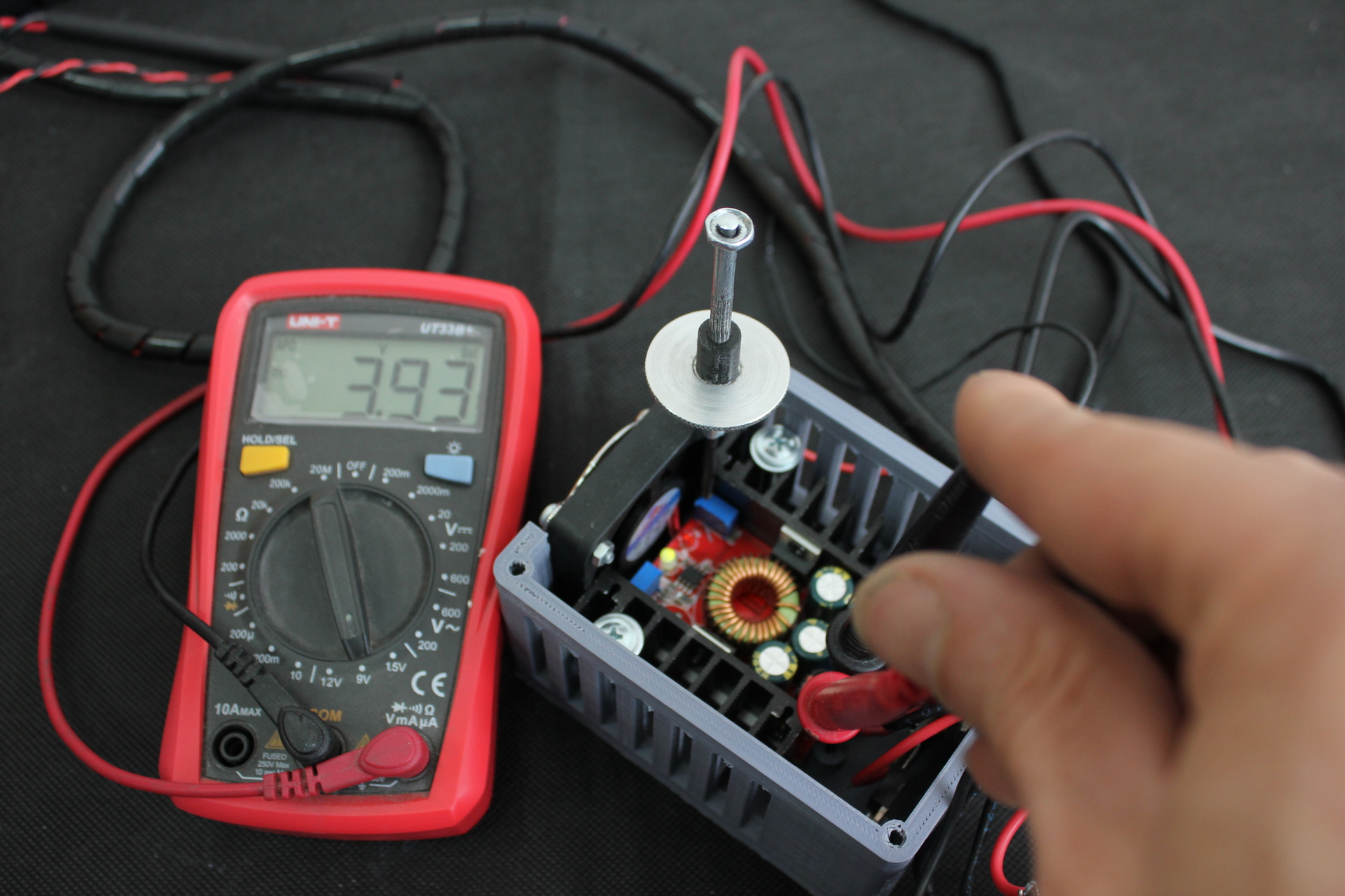
To configure, we need 2 multimeters – one for taking readings of the current value (hereinafter referred to as an ammeter), the second for taking readings of the voltage value (hereinafter referred to as a voltmeter). One multimeter can be used, but this will slow down the tuning process. A calorimeter will also be needed to measure the thermal power of the tuned laser.
Before starting the setup, make sure that the laser control button is in the “OFF” position

We connect an ammeter in the measuring range of 10A. Positive (red) wire of the ammeter to the positive (red) wire from the control unit, negative (black) wire of the ammeter to the positive (red) wire of the laser diode.

We set the voltmeter in the measurement range of 7-12V.

The laser control button remains in the “OFF” position. We measure the voltage at the DC-DC output.

The voltage 4.63V corresponds to the permissible one. For safety reasons, using a voltage regulator, we reduce the voltage at the DC-DC output to about 4V. This is done so that when the laser is first turned on, not a very large current flows to it.
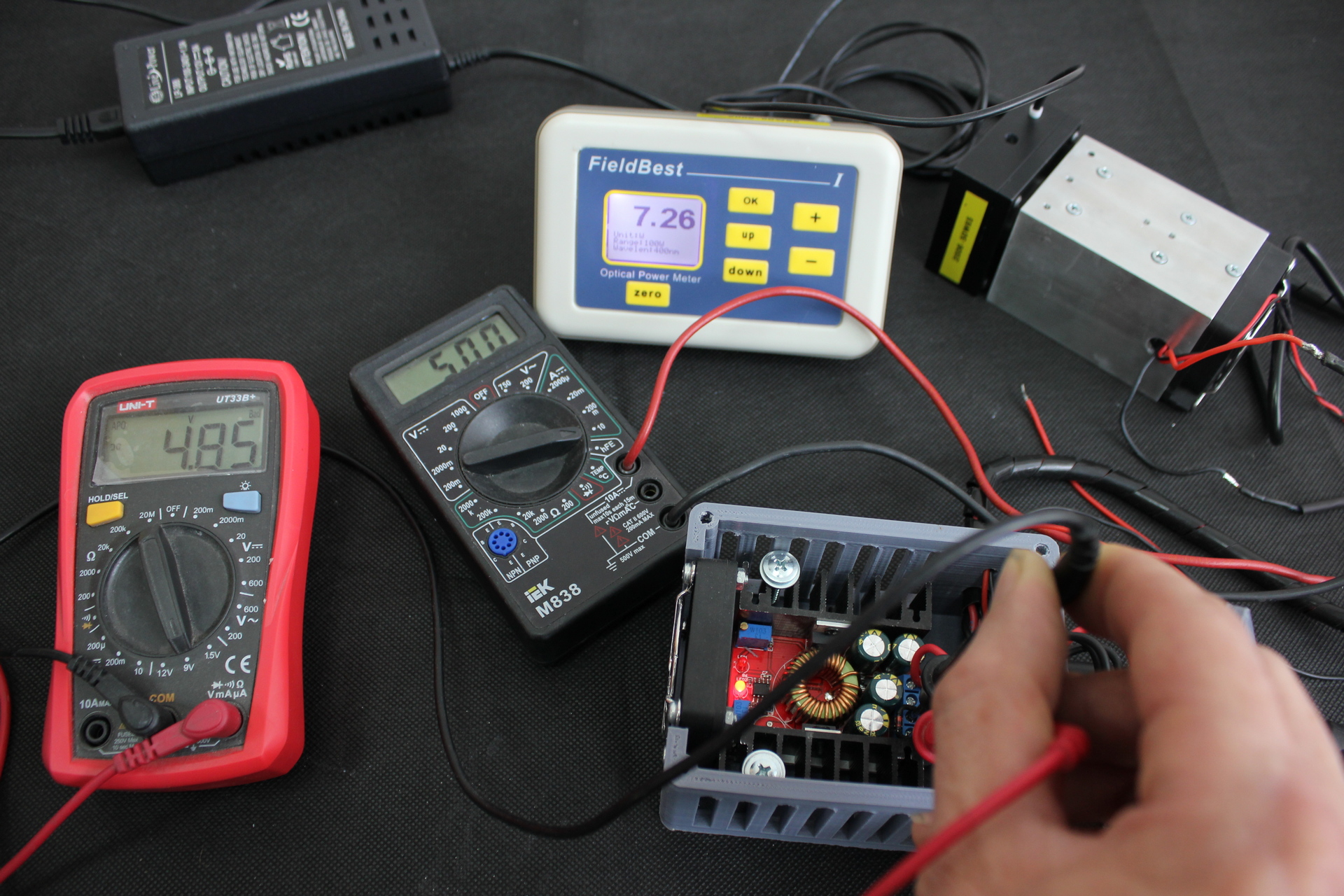
We turn on the laser in the “FULL POWER” mode.
Laser current 1A, output power 1.28W. Gently start increasing the voltage to increase the current. The recommended optimal current is 4.3-4.4A.
WARNING: Regulators are very sensitive. Turn the adjusting screw very slowly and carefully.
During the adjustment process, a situation is possible when during the rotation of the screw by 180-360 degrees (half-turn-turn) the current stops growing. This may be due to the fact that the current limit was set using the limiter. In this case, it is necessary to reduce the voltage by 1V. Then turn the screw on the current limiter 2-3 turns. Then the process of raising the current can be continued.

Presetting result: Output voltage DC-DC 4.64V, laser current 4.04A, output power 6.46W.
Let’s raise the current to 4.3A.

Output voltage DC-DC 4.71V, laser current 4.36A, output power 6.75W.
The 4.71V voltage is slightly higher than 4.65V, but this is acceptable now.
Now we measure the voltage across the laser diode. To do this, we connect the voltmeter to the wires coming from the laser at the point where they are soldered to the wires coming from the control unit. When using 2 multimeters, the positive (red) wire of the voltmeter is connected in the place where the negative (black) wire of the ammeter is connected.

The voltage across the laser diode is 4.35V.
Since the multimeter has its own resistance, when we disconnect the ammeter from the circuit, its resistance will decrease and the current will increase by about 0.2-0.3A. In order for it to remain in the desired value, we will reduce it by 0.3A. You can also use a current limiter. To do this, you can slightly raise the current – by 0.05A and use a limiter to reduce it. After adjusting the limiter, the current must still be reduced by 0.2-0.3A.
After the adjustment is made, disconnect the ammeter and solder the positive (red) wire from the laser diode to the positive (red) wire coming from the control unit.

We connect the voltmeter to the soldering point of the laser diode wires and the wires of the control unit. We raise the voltage to 4.35V.

The voltage across the laser diode is 4.37V. The specificity of DC-DC adjustment is such that it is quite difficult to set the voltage with an accuracy of 0.01V. In addition, the measuring instruments themselves have an error in the readings. Therefore, a discrepancy of 0.02 is acceptable.
Now we measure the voltage at the DC-DC output.

Output voltage DC-DC 4.65V, which corresponds to the permissible value.
This completes the laser setup.
We isolate the soldering points of the wires. To do this, we put on heat-shrinkable tubes at the places where the wires are soldered and we seat them with a special hair dryer. You can also use a regular lighter instead of a hair dryer. This must be done carefully so that the insulation on the wires does not melt. For reliability, you can use another heat-shrink tubing for general insulation of the “laser” pair of wires. In the absence of a heat shrink tubing, ordinary electrical tape can be used to insulate the wires.
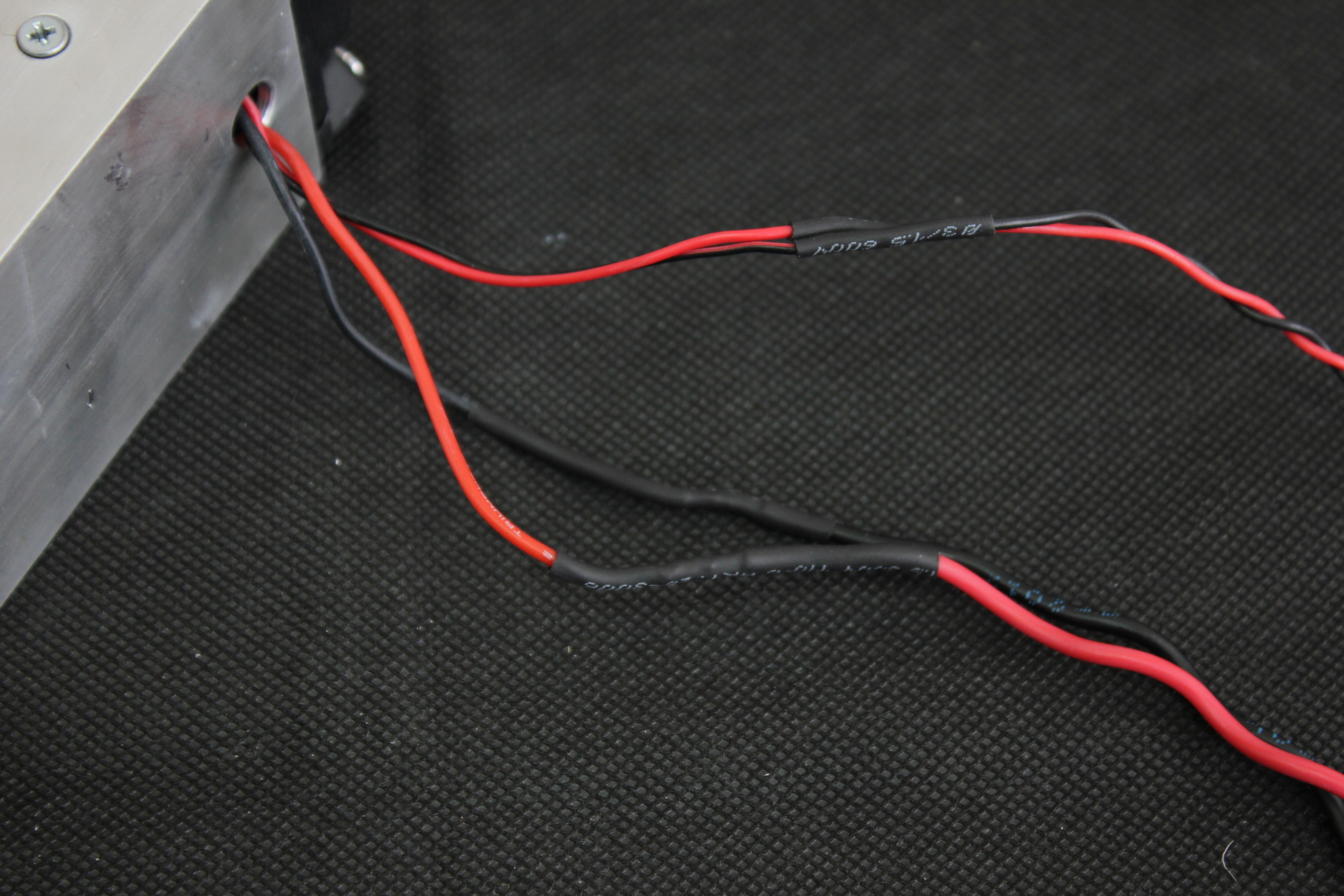
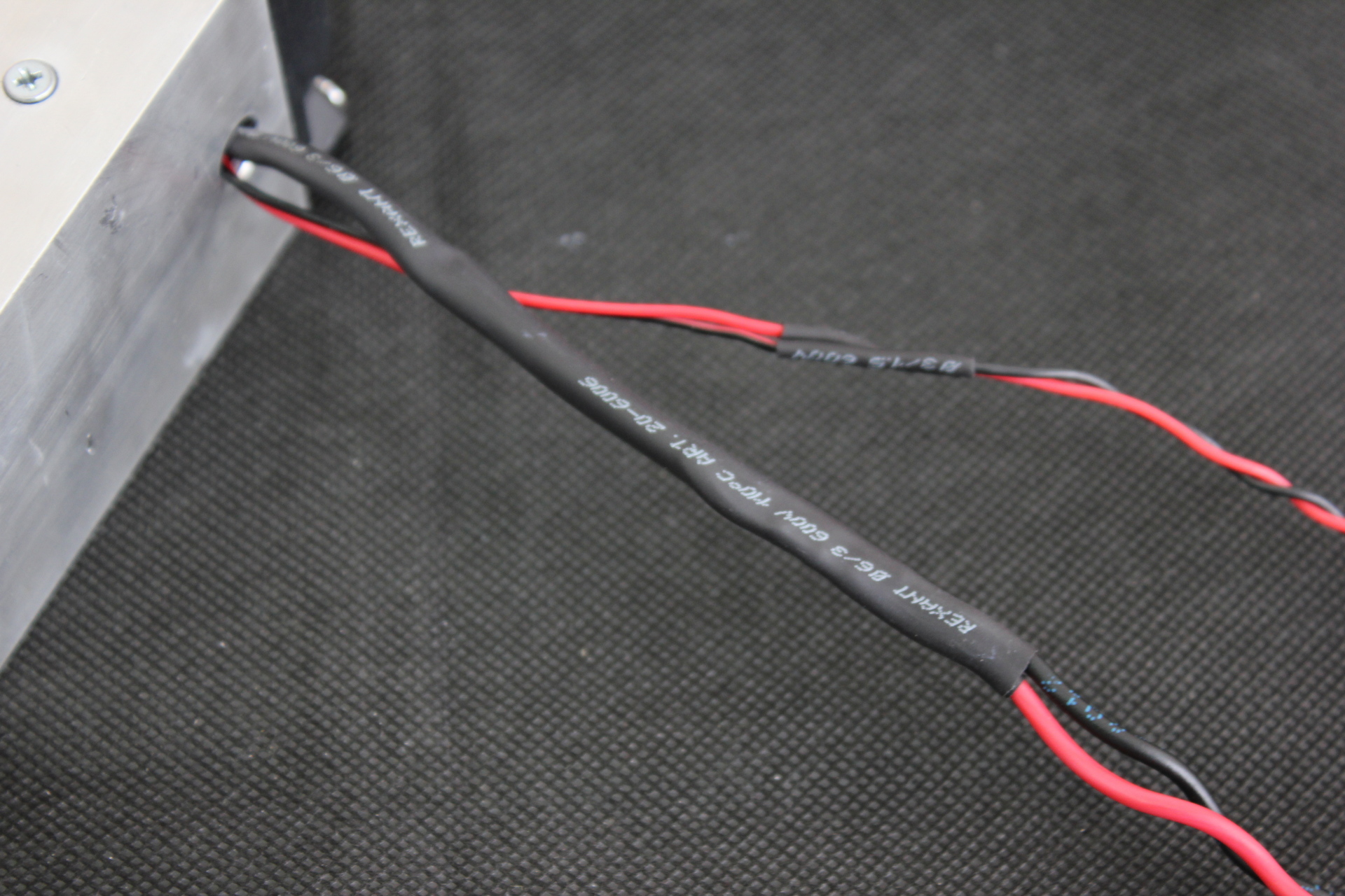
Then we wind the braid on the wires, screw the cover of the control unit into place, put the lens. The laser is ready for use.

ADDITION
The laser diode can supply it with a current of 5A. This increases its power, but this operating mode is close to the limiting capabilities of the laser diode and can shorten its life. In addition, not every control unit will allow a current of 5A to be supplied in normal mode, since the DC-DC output can produce a voltage of more than 5V, which can also damage the laser diode. In addition, at a higher current, the heat release of the laser diode increases and it must be cooled more, since a higher temperature can also affect the life of the laser diode.