
Introduction to CNC for a Total Novice
Part of a series by Graham Bland
Setting up an Endurance Laser on a 3018
Contents
- Introduction
- Other files in this series
- Disclaimer
- Accompanying files
- Background reading
- Endurance Lasers
- Some terms and descriptions
- What’s in the package?
- SAFETY!
- Mounting the Laser
- Putting it together.
- Connecting the Laser Control module.
- Laser Beam and Focus.
- Maintenance
- Regaining Cutting area
- 3D Printer Notes
Introduction
An introduction on how to mount, connect and setup an Endurance 10W laser module on a SainSmart 3018-PRO or PROVer CNC Router running the Grbl control system.
A lot if not all of this will apply to other 3018 routers, in fact it should be the same for any 3018 using a 42mm 775 spindle motor mount.
What am I using?
- A SainSmart 3018 Pro CNC router.
- A SainSmart 3018 PROVer CNC router (optionally with the 3040 extension kit).
- An Endurance 10W Plus diode laser module and power supply. (Applies to the Std version as well)
NOTE: There is an increasingly misleading habit developing of Laser Sellers to quote the INPUT power of the Laser, this is a meaningless figure but is often used as it is a bigger number and looks better. Endurance Lasers and other reputable sellers quote the OUTPUT power of the Laser which is the only figure that matters. An Endurance 10W Laser has an output power of 10W. Note the power supply is rated at 6 Amps at 12V which would give it an INPUT power of 72W!!!
I am producing this as a document, mainly because it is an edited series of notes I made, partly because I am tired of watching instructional videos on YouTube which play at Mach 2 and so I am constantly stopping, rewinding and re-watching. Also I have been told I have a body made for Radio, a voice most suited to the Deaf and I still haven’t worked out how to use the video camera on my phone properly.
Other files in this series
All these are in the files section of the Facebook SainSmart Genmitsu CNC Users Group (https://www.facebook.com/groups/SainSmart.GenmitsuCNC/) and other locations. there may be more or less guides as I am not going to update everything if I add a new one or remove one.
Find them in the files section of the Facebook group by searching for ‘Introduction to CNC for a Total Novice’ Or ‘Introduction to CNC for the Total Novice’ Consistency has never been one of my strong points, just search for ’Introduction to CNC’!!
| Title | Contents | FaceBook link | ||||||||||||
| – Getting Started | Introduction to the process and how to check | https://www.facebook.com/groups/SainSmart. | ||||||||||||
| and test your 3018. READ THIS FIRST! | GenmitsuCNC/permalink/2352850398359114/ | |||||||||||||
| – Making a Spoilboard | Example of how to cut, fix, face and engrave | https://www.facebook.com/groups/SainSmart. | ||||||||||||
| a 3018 Spoilboard with specific instructions | GenmitsuCNC/permalink/2451607738483379/ | |||||||||||||
| for 3018-Pro and PROVer. | ||||||||||||||
| – Setting up a Laser | Fitting, focussing and starting out with a Blue | https://www.facebook.com/groups/SainSmart. | ||||||||||||
| Diode Laser on your 3018. | GenmitsuCNC/permalink/2356427874668033/ | |||||||||||||
| – Tuning Grbl Settings | Exploring the optimized settings for your | https://www.facebook.com/groups/SainSmart. | ||||||||||||
| 3018 to make it faster and better. | GenmitsuCNC/permalink/2373672706276883/ | |||||||||||||
| – Spindle Speed and Laser Power | The relationship between the Spindle Speed | https://www.facebook.com/groups/SainSmart. | ||||||||||||
| and Laser power of your 3018 and how to set | GenmitsuCNC/permalink/2531618443815641/ | |||||||||||||
| the values. | ||||||||||||||
| – Basic Gcode for Grbl | Introduction to Gcode on Grbl based routers | https://www.facebook.com/groups/SainSmart. | ||||||||||||
| plus non Gcode control commands. | GenmitsuCNC/permalink/2705472216430262 | |||||||||||||
| – Bits | Bits! The types, common terms and | https://www.facebook.com/groups/SainSmart. | ||||||||||||
| descriptions and how they work! | GenmitsuCNC/permalink/2705982476379236/ | |||||||||||||
Versions of a lot of these along with more information and resources, yes there are other people who do this sort of thing, can be found on at https://docs.sainsmart.com
Disclaimer
Yeah nowadays it has to be included, and it makes sense as I accept NO liability for anything I may say, write or think.
- I am a total novice (or was when I started out). I MAKE NO CLAIM THAT ANYTHING I SAY IS CORRECT! All this is based on searching the Internet, forum comments…. and my own experiences.
- This is based solely on the equipment I have, if there are variations or different versions out there I have not seen them.
- If you have and are using a Laser module, even the lowest powered is powerful enough to destroy your vision completely, and that of any pets, children, spectators etc. SO EXCLUDE THEM AND USE THE GOGGLES!
- These are power tools, sharp pieces of metal designed to cut things while rotating at high speed and throwing small bits away also at high speed. Keep everybody’s fingers out! A wood chip flying up your nose is nothing to be sneezed at, never mind in one of your eyes.
- Take account of the materials you are using and take adequate precautions, dust and ashes can be harmful.
- I work in mm. Why anyone still uses inches for design work is a mystery. But then I still think of temperatures in Fahrenheit, anything beyond 100m in miles and property plot sizes in acres!
- I have been told by lots of people that my sense of humour is at the least a bit strange. I do not apologise for it.
Any corrections, clarifications or discussion welcome. You can find me on the Facebook SainSmart
Genmitsu CNC Routers Group as Graham Bland. https://www.facebook.com/groups/SainSmart.GenmitsuCNC/
Accompanying files
NOTE: Facebook has a problem, it will not allow compressed (.zip, .gz, ……) to be uploaded to the
Files section of any group, but it bases this decision solely on the file extension, not the contents.
It is easy to bypass this by changing the file extension before uploading, I use .zip files, and rename them to .zipp This means that after downloading you will have to reverse this by renaming any xx.zipp file to xx.zip, windows will issue warnings that you are probably going to make the file unusable, just ignore it and rename anyway. Then you can open and extract the files as you wish.
So there should be 2 versions in the files section. One an xx.pdf which is the basic words, and if there are any accompanying files with it an xx.zipp with the .pdf and everything else.
Accompanying files for this are:
| Laser Mount.stl | 3D printable file of the laser mount. |
| Top Clip.stl | 3D printable file of the laser mount top clip. |
| Air Assist Clip.stl | 3D printable file of the air assist tube clip. |
| Alignment Tool.stl | 3D printable file of the laser alignment tool. |
Background reading
If this is your first laser I strongly recommend reading my guide “Introduction to CNC for a Total Novice – Setting up a Laser” first as it covers more detail on how they work setting up software etc.
This can be found on the Facebook SainSmart Genmitsu CNC group in the files section. A direct link is https://www.facebook.com/groups/SainSmart.GenmitsuCNC/permalink/2356427874668033
Endurance Lasers
Endurance sell and support a variety of high quality and high power Lasers more information at https://endurancelasers.com/
In this guide I am only covering their 10W Blue Diode Lasers. This is available in 2 models, the standard and the Plus. Both have identically sized laser heads so this applies to both models, the Plus has an enhanced control box and is fitted with an Air Assist.
Some terms and descriptions

The diode creates a beam of light, this passes down through a cavity in the Heat Sink. It then passes through lenses which focus the beam.
The Endurance Lasers are Fixed Focus, this means the lens assembly has been pre-set to the optimal focus point. It can be adjusted if you wish by unscrewing and removing the spacers, but why would you want to? (That was a rhetorical question)
Focal Length
The Focal length is the distance of the Focal Point from the laser. I measure it as the distance to the bottom of the Heat Sink, not the lens which would be more accurate but setting the distance from the bottom of the Heat Sink is much easier, safer and more practical.
Focal Point
The Focal Point is where the beam converges into a tightly packed dot before expanding again. This is where the laser is most effective.
Focal Range
This all depends on the beam quality, it’s the distance where the beam can be considered to be in focus. A narrow beam will have a longer focal range, a thicker beam will have a shorter focal range.
What’s in the package?
This varies slightly depending on the model and package you purchased but will include:
Laser Head
This is the bit that that mounts onto the CNC machine and holds the Diode and Lenses surrounded by a heat sink with a cooling fan on the top.
Laser Control Module
This takes the PWM signal inputs from the Router and power and converts the signals to control the Laser output power and cooling fan. Two versions the standard and the plus version, the plus has extra displays on It to show you what is happening.
Power supply
The laser takes its power from a dedicated mains power supply rather than from the router Mainboard.
Cables
The connections from the Router Main Board to the laser are not standard, there are different cables for different connections, only a 2-pin connection is needed to the Main Board from the Laser Control module PWM wires. It is very important to verify the individual pins are connected correctly, there is nothing to say a 3-pin connector on the mainboard must have the pin order PWM|Gnd|12V or 12V|PWM|Gnd. Other pin orders are also likely.
Safety Goggles
Essential, See Safety! The ones supplied work and provide all needed protection for these lasers. But ensure every living thing that may be in sight of the Laser wears them. (OK I will exclude spiders and cockroaches but definitely not exclude cats, dogs, children etc.)
Bits and pieces
Nuts and bolts, some generic mounting brackets, cable connectors, stickers……… There is one thing
you may find strange at first glance, a blank anodised aluminium business card. This is actually an ideal focussing and Laser test plate.
Air Assist
On the Plus version an air assist tube and nozzle are mounted on the laser head and tubing supplied to connect to an air pump.
SAFETY!
Lasers can engrave lots of things, some of the things it can easily engrave are the retina of the eye and flesh! OK all this is in the disclaimer but is worth repeating!
Please keep at the forefront of your mind that for even a Low powered laser to damage your eyes you don’t have to stare into it for a couple of minutes, it doesn’t even need to be focused directly in your eye to burn the retina, Lasers do not exist in nature so eyes did not evolve to deal with Lasers! Everyone should know that looking directly at the sun is a very bad idea but it’s probably safer as your eyes will automatically try and limit any damage, they won’t for a laser beam.
This is the reason that the laser comes with a pair of safety goggles, USE THEM! They are designed to limit the amount of light in a small range of frequencies which can pass to prevent any damage; they tend to be specific to particular lasers which use different wavelengths of light. The supplied goggles are designed for use with the laser you bought. (If you use a different laser then you will need something suitable for the frequency of that laser).
Reflections can be as damaging, so don’t just think of yourself. Exclude Pets and others from the area when using a laser; make sure windows are covered…..
A second other consideration is the burn, melt or vaporise bit! If cutting a flammable material, for example paper, it is quite possible to set it on fire. If cutting a material such as MDF from which the dust can be toxic, the fumes from burning are also toxic. Hitting a resin pocket in a piece of pine can cause a fire.
At the absolute minimum use in a well-ventilated area, wear a face mask as well as the goggles if there is a possibility of the stock being toxic and keep a very damp cloth handy. But it’s your health and you have been warned.
Mounting the Laser
Well, the Endurance Laser is big, it has to be to give the needed cooling and power output. Most lower powered laser heads for the 3018 come in a 33 by 33mm package which fits into the slots on the motor mount. The endurance Laser head is 50 by 50mm so it won’t fit.
Design Notes:
- wanted:
- Something which will minimise any loss of engraving area on all the axes.
- Be quick and easy to swap for a spindle motor.
- Be height adjustable to maximise the ease of setting the correct focus height and allow the largest range of material thickness which can be cut or engraved.
- No modifications to the basic motor mount or drilling and tapping holes in anything.
- The profiles of the 3018 Pro and PROVer motor mounts are similar but slightly different. The design must fit both.
This resulted in the following decisions.
- The Laser is mounted on the front of the existing motor mount, this gives unimpeded X and Z axis movement but the closest I can get the laser beam to the spindle motor centre on the Y axis is 52mm. This can be compensated for, see later.
- I made a new air assist mounting to move it from the side of the laser to the front where it is more out of the way.
You will need access to a 3D printer to make your parts, all the models and some printing details included here. Or I will sell the printed parts (I’m in England but will post anywhere at cost) If you want the printed mounting set then please email me at grahambland.guides@google.com for an up to date price and postage to your location.
The mounting system comes in 3 parts.
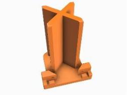
Laser mounting bracket
The ‘X’ fits into the existing laser mounting slots and can be easily slid up and down to set the height. It is secured using the original clamping bolt on the motor mount. The laser head slots snugly into the base and two 3mm screws attach the Laser head using the existing mounting holes.
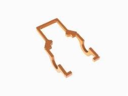
Top Clip
This is a slide on fitting over the X on the mounting bracket and clips round the corners of the Laser head. The purpose of this is to prevent the laser head tilting around the ZY axis, without it it’s a bit floppy. Rubber bands keep the sides of the clip snug to the laser head.
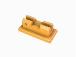
Air Assist mount
The original air assist pipe is mounted using a bolt and screw arrangement at the side of the laser head. This modification prevents the pipe mounting fouling on any side guards which may be fitted by moving it to the front using a stick-on clip.
Other bits needed
- 2 rubber bands
- 2 M3x6mm or longer flathead/countersunk screws. These came with your Endurance Laser.
- 2 M3x3mm grubscrews or 2 M3x6mm screws Only needed if using the Air Assist and they are needed to secure the pipe in the clip.
Putting it together.
Step 1 – Remove existing Air Assist mount (If Fitted)
If you have the + model and want to use the front mounting for the air assist remove the pipe mounting by undoing the nut on the inside of the Laser Head, this is only necessary on routers which have side panels fitted and then only if needed to prevent the air assist pipe and it’s mounting from contacting the panels or the side of the router.
Remove the plastic tubing from the end of the pipe and slide the pipe out of the mounting. It will be refitted later.
Step 2 – Mount the Laser head to the Laser Mount

Slide the Laser head into the slots in the base of the Laser Mount and secure in place using 2 M3x10 flat-head/countersunk screws (these came with the Laser, if not M3x6 or longer will do just as well). Tighten the screws snugly but gently. Do not over tighten, the amount of plastic round these is small due to the tolerances necessary to mount the Laser head close to the motor mount.
Step 3 – Slide the Laser mount into the motor holder

Slacken the clamping bolt on the motor mount and slide the X into the motor mount. You may have to raise the motor mount on the Z axis of your router first.
The front 2 corners of the X are rounded to make insertion easier so locate the back two edges in the slots first and then slide the front ones into the front slots. Depending on your motor mount it may be necessary to use a flat head screw driver or thin spanner to prise open the slot in the motor mount first. Slide it up so the top of the x sticks out from the top.
Step 4 – Fit the Top Clip

Fit a rubber band (not shown, have you ever tried to model a rubber band in a CAD system?) round the top clip over the notches just behind the back of the laser bed, this keeps the side arms held against the laser head.
Slide the long arms of the top clip onto the laser head below the cable exit and then slide the back square over the top of the X on the motor mount so the small tabs touch the top of the X and the top of the arms are aligned with the top of the laser head.
Use another rubber band to hold the front corners of the top clip securely onto the body of the laser head.
Step 5 – Fit the Air Assist (if needed)
If using an air assist push the pipe into the mounting clip from the end through the hole or clip into the top.

Optionally fit 1 or 2 M3 screws (3mm+ grub or 5mm+ screws or bolts) into the holes on the clip to lock the tube in place.
Attach the mounting clip to the front of the laser head using a good double-sided tape (Glue works but can be too permanent). Place in the centre of the Laser head with the bottom of the base about 10mm above the bottom edge of the laser head. Make sure that the tube can slide enough in the clip to reach the focus point of the laser. The Air Assist pipe (included with the +) is a 4mm outside diameter pipe. The clip is designed to take this pipe diameter.

Connecting the Laser Control module.
There are a multitude of router control boards out there, too many to describe in detail. These instructions cover connecting the Endurance Laser Control Module to the current SainSmart 3018 boards for the Pro and Prover models running Grbl. If your router is different the precise instructions may differ, but the principles are the same.
The Endurance Laser control module has two PWM input wires, these give the router mainboard control over the laser power by outputting a PWM signal consisting of off and on pulses. (All pulses on, laser is at 100% power, constantly on. All pulses off, laser is at 0% power, constantly off) Your router mainboard will have one or more Laser control sockets with either 2 or 3 pins. The pins should be labelled, one will be marked gnd or -, one should be labelled either PWM or TTL, possibly Signal or 0-5V depending on your board. If there are 3 pins then one will be marked as 12V or something similar.
If the socket has 3 pins then never connect the 12V pin, the laser is supplied with power by its own power supply. Please Note I don’t have any other mainboards than these so if yours is different please consult the manufacturers instructions.
My Laser was supplied with a variety of connectors along with what I can best describe as a very useful cable joiner, pick the connector that best suits your mainboard connections.
It is STRONGLY recommended that when you connect the Laser you also disconnect the spindle motor. Not only does this prevent an unattached spindle motor suddenly starting up it also protects the circuitry of your router’s mainboard!!!
Connecting to a 3018 PROVer
On the right-hand side of the Mainboard are 3 white sockets. The centre socket is used for the PWM signal to the laser and is marked (PWM [+ and –]).

Connect the top pin (PWM +) to the red wire from the Laser Control Module and the bottom pin (PWM –) to the black wire.
Connecting to a 3018 PRO

At the top of the mainboard is a red 3 pin socket marked from left to right 12V, PWM and Gnd.

Connect the Middle (PWM) pin to the red PWM wire on the Laser Control module and the right (Gnd) pin to the black wire PWM wire on the Laser Control module. The leftmost 12V pin must be left unconnected.
Startup Warning
I have found that both powering on the router and connecting it to software on my PC can cause the laser to fire for a short while, this can also happen when powering on the router.
If for example the PROVer mainboard has the power switch turned off or is just connected by the USB port the PWM output will be indeterminate resulting in the Laser firing even when set to PWM mode!
Make sure when powering it on that your goggles are on!
This can also damage the stock, so it also makes sense to put something non burnable under the laser before turning the router on and connecting to any software.
Laser Beam and Focus.
The Endurance Lasers are supplied with the lens already focussed, the focal length and range have been pre-set and the position of the correct focus point is adjusted by setting the distance of the Laser to the stock.

Simplistically the Laser beam comes out of the lens and follows the shape of two cones joined at their points. Setting the focal point is just a matter of adjusting the height of the laser above the stock so that the intersection of the two cones is where we want it, at the top surface of the stock. At this point it will make the smallest possible dot so focussing all the laser power into as small a point as possible.
As it is being mounted onto a 3 axis machine the height above the stock can be adjusted in two ways;

- By sliding the X of the mount up and down in the motor mount.
- By using the Z axis jog controls before setting the Z axis zero point.
If cutting or engraving on a curved / angled surface the Z axis height can be controlled by the Gcode to move up and down as required.
This is different from mounting on a laser engraver, they are normally 2 axis machines, the Z height is fixed so the focus point can only be adjusted by adjusting the Laser mounting or stock height.
Setting the height for the first time
The reason I say for the first time is that to make life easier once I have set the height of the focus point, I then make a Laser Alignment tool, just a simple spacer cut or printed to the distance between the top of the stock and the bottom of the outer heatsink. When changing stock, swapping the Laser out for a Spindle and back I use the alignment tool to set the correct height. This makes adjusting the focus point much quicker and easier.
The Endurance Laser came with a black anodised aluminium ‘Business card’ this is ideal for setting and checking the Laser Focus, it’s thin, flat and will not burn easily at the focussing power of the Laser.
There should be a card giving the model, date voltages etc. On this there is a “focal range:” line which indicates whereabouts the focal point has been set. On mine this is 51-59mm, giving a midpoint of 55mm. These distances are measured from the Lens.
It’s not a good idea to stick rulers or other devices into the lens even once. The bottom of the lens on mine is ~3mm proud of the bottom of the outer heatsink, so I am just going to use the heatsink and ignore any difference for the moment.
- Jog the Laser Head to a convenient point on the X and Y axes and place the ‘card’ underneath the laser on the top of the bed or spoilboard, there is no need to clamp or secure it.
- Jog the Z axis to the approximate centre of its travel, this gives maximum adjustment for moving the focal point.
- Slacken the clamping bolt and slide the mounting bracket in the motor mount until the outer heatsink of the laser head is 55mm (the midpoint of the focal range) above the top of the ‘business card’.
- On the laser control box set the laser power to Focus and turn it on.
My apologies but it is very tricky to photograph the dot! With the goggles on (Don’t look at it without them!) you will see a small red dot. The goggles will also hide any extraneous light which may be emitted by the laser, only the central dot is important.
The photos I am using come mainly from a cheap USB microscope set up to be focussed on the dot.


The aim is to raise and lower the laser head until the dot is round and is the smallest it can be made. It’s just the centre of the dot that matters, there will be some overspill which should be ignored, the goggles will make this practically invisible anyway.

Out of shape – not round Too large and uneven Still too large Perfect
Above are some images showing the out of focus and in focus images I obtained.

Once you have the focus distance set then measure as accurately as possible the distance to the heatsink from the top of the stock. In my case it seems to be best at 56mm.
Now you can print the Laser Alignment Tool, but before slicing scale the Z axis to your distance value in your slicer.
Anything cut to the correct length will do the job!
Setting the focus with a Laser Alignment tool
- Mount the stock on the bed or spoilboard.
- Use any required combination of sliding the X up and down in the motor mount and Z axis jog controls until the alignment tool just fits between the top of the stock and the bottom of the heatsink.
- Make sure if you are cutting or engraving on a curved or sloped surface that the Z axis has sufficient room to move down to your required cut depth.
- Tighten the motor mount clamp to secure.
- Check the focus, fine tune with small jog steps on the Z axis if needed.
- Zero the Z axis.
Much simpler and quicker!
Maintenance
Not a lot needed, but the processes of using the laser will generate smoke and soot. Every so often clean the outside of the focusing lens. I use a cotton bud dampened with lens cleaner (or window cleaner), then use the other end to polish it dry. Repeat until the cotton bud comes out clean.
Regaining Cutting area
The X and Z axes are unaffected by the laser mounting, but the Y axis will loose 52mm due to the centre of the laser head being that far from what would be the centre of the spindle.
There are 3 ways of compensating for this if needed:
- Just extend the stock over the front edge of the bed. Obviously this will only work for rigid materials, not such a good idea if engraving on leather for example.
- Add an extra spoilboard underneath the stock and fixed to the bed hanging 52mm over the front edge of the bed. This just needs to be flat and rigid enough to support the stock. (6mm MDF works fine.)
- Move the Gantry supports back on the router frame, much more complex and really only suitable if you are planning on permanently mounting the Laser, there is ~36mm available on the PROVer and ~45 mm available on the Pro (both from SainSmart, other makes may differ). The disadvantage of this is that you lose the ability to surface the spoilboard to make it level across the movement of the X and Y axes.
3D Printer Notes
- The parts I am using are all printed using PETG, this is helpful for the top clip as it makes it a bit more flexible than PLA to allow easier fitting, also it was the filament I had most of.
- All parts have been printed using a line height of 0.2mm with a 0.4mm nozzle. In my case using a Creality CR6SE and a BIQU-B1.
- Remember if printing the Laser alignment tool to scale the Z height to your measured distance before printing.