 - a custom solution.")
Product description
Scope: drying insects. Alternative installations are dried by convection of warm air, and we need a direct effect of the heating element on the object
Components list
| Thermostat |
| Thermocouple |
| Time relay |
| Phase voltage regulator |
| Ceramic infrared heater |
| Heat-resistant wire |
| Heating indication lamp |
| Illuminated ON-OFF switch |
| Relay for heater |
| Relay socket |
| Switch black |
| Automatic switch |
| Indicator lamp for exceeding the temperature |
| Indication lamp on fan |
| Heat-resistant duct fan |
Drawing, sketches, and wiring diagram, how to run
Wiring diagram

IR HEATING BOX MAINTENANCE MANUAL

GENERAL SAFETY INSTRUCTION
This maintenance manual is intended for user guidance on the IR heating box operation handling and safety rules.
This manual should be always available to the operating and maintenance personnel.
Those who have not read or understood the guidance on the operation and safety rules are not allowed to use the IR heating box.
CONNECTION REQUIREMENTS
Assembly and installation of the IR heating box should be done only by professional specialists in compliance with the guidance. The IR heating box should be connected to a reliable ground system that complies with the current electrical safety regulations.
The manufacturer disclaims any responsibility for damage that may be caused to people and property in the absence or poor-quality grounding of the device.
Before using the IR heating box for the first time be sure to check that the inner chamber of the IR box is empty.
Installation, connection, and operation of the IR heating box with mechanical damages of the apparatus, power supply wires etc. is prohibited.
SAFETY REGULATIONS
While on operation the IR heating box is getting warm. Its inner surfaces, the heating elements, and the outside housing become hot. Open it using a handle on the box door only. Stay nearby the IR box. It is forbidden to leave the IR box unattended by the person authorized to operate it when the IR box is powered (the ON/OFF switch is in the ON position).
Power cords of the IR box or other devices should not be in contact with the IR heating box housing.
Unplug the device if any problem occurs.
The IR box continuous operation time should not exceed 60 minutes. After an hour of operation switch off the box and leave it to completely cool (the inside temperature of the box must go down to the room temperature).
SPECIFICATIONS
External dimensions 488mm x 403mm x 579mm (LxWxH)
Internal dimensions 269x346mm x 291mm (LxWxH)
Weight 20 kg
Power supply 230 V AC, current / 50 Hz / 2100 W
The maximum allowable working temperature inside the IR box 150 С
Automatic control of the set temperature inside the IR heating box No (optional)
Heating power setting Yes triac regulator
Heating operation time set by the timer 1-999 sec
Positive heating activation Yes toggle switch
The temperature of forced heating shutdown
to prevent the IR box damage 150 С and alarm indication
Operation time at the maximum temperature No more than 60 min
Forced ventilation Yes, manual, toggle switch
Ventilation flow control louvers, manual
INSTALLATION
After unpacking, place the IR heating box 1 in a stable position on a high heat hard base. The distance between the sides of the IR heating box 1 and other electrical devices, as well as from flammable objects, must be at least 1 meter.
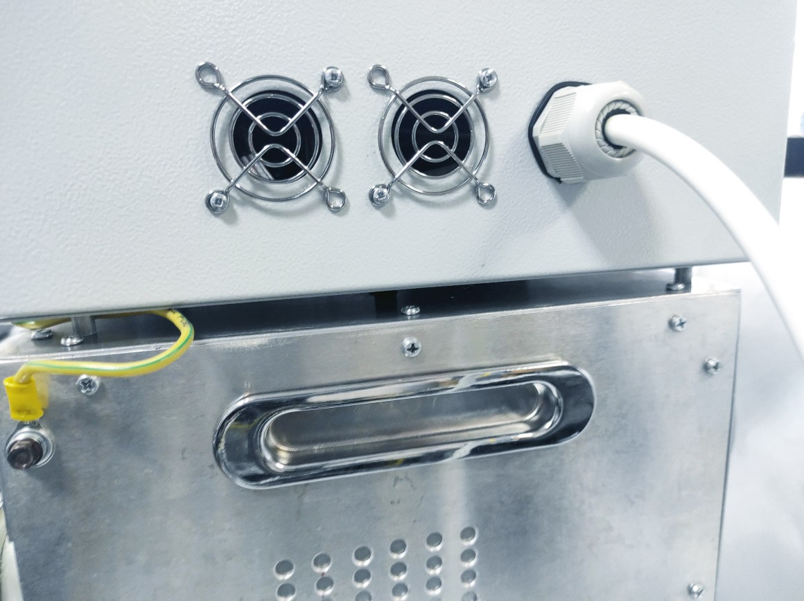
Use a 16 A 230 V / 50 Hz grounded socket to connect the apparatus to a power supply. The apparatus is equipped with a 16 A / 230 V grounded plug and a 1.5 m connection cable.
Connect control unit 2 of the IR heating box 1 to the local ground network via grounding terminal 8 on the front panel (right bottom) of the control unit 2

Fig. 1. The grounding terminal of the control unit.
Maintenance

Main elements of the inner chamber
Fig. 2. Main elements of the inner chamber
1 – adjusting screws, 2 – removable (adjustable) bottom of the IR box, 3 – thermocouple to control the inside box temperature, 4 – in-take air louvers, 5 – fan, 6 – IR heating elements)

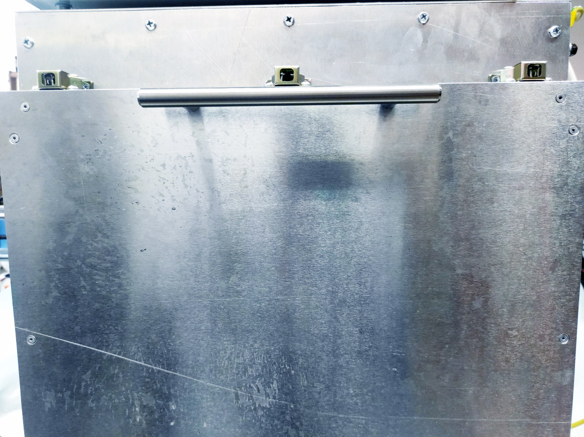
IR Heating Cabinet, general view
Fig 3. IR heating box, general view
(1 – box door, 2 – door handle, 3 – grounding terminal, 4 – IR heating box control unit, 5 – transportation handles of the IR box, 6 – in-take air louvers
- Open box door 1 using door handle 2 (Fig. 3).
2 . Set adjustable bottom 2 at the height you need using adjusting screws 1 (Fig. 2). Place a pallet into the box (not shown). Install thermocouple 3 (Fig. 2) at the place where you need to control the temperature. Close box door 1 (Fig. 3).
- Open and close the air-intake louvers 6 (Fig. 3)
4. Switch on the cabinet.
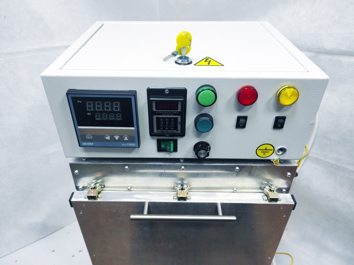
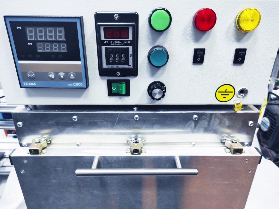
CONTROL ELEMENTS OF THE IR HEATING BOX

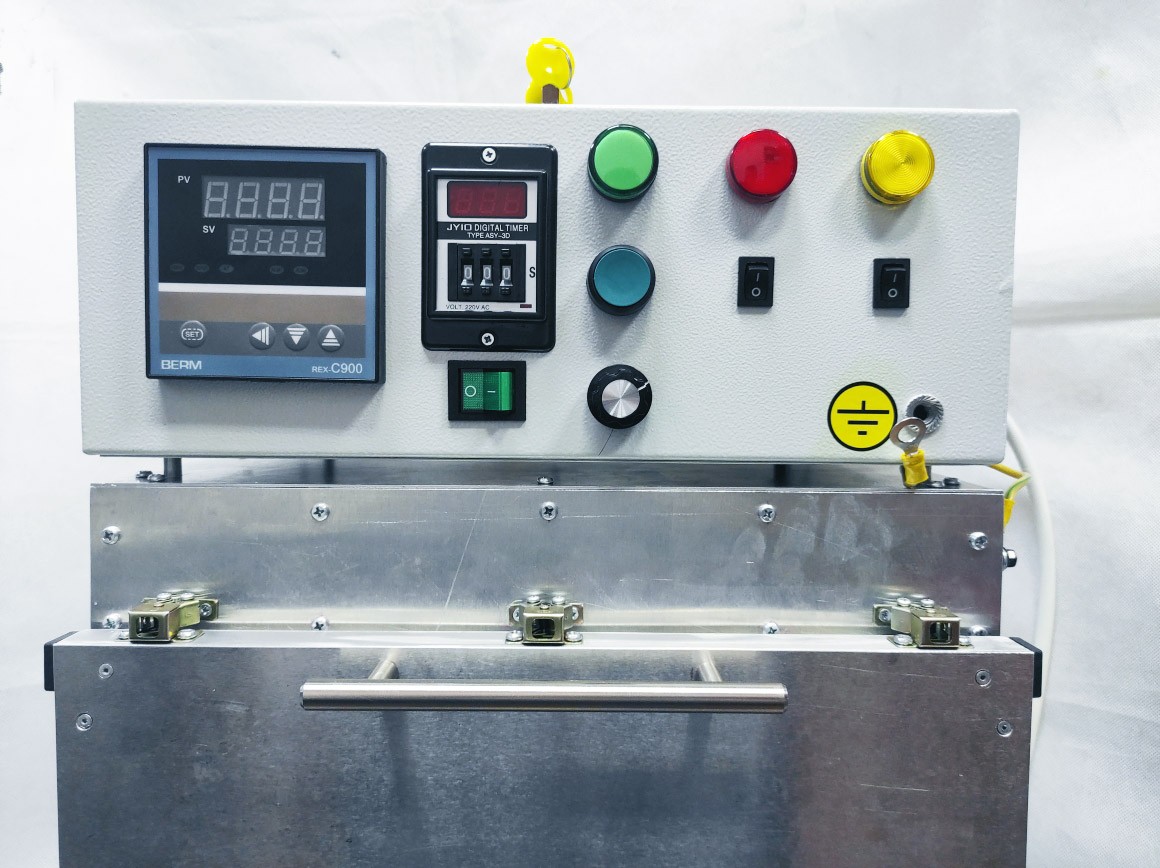
Fig. 4. IR heating box control unit
(1 – thermocouple current readout 3(Fig. 2), 2 – Maximal allowable heating temperature of the IR heating box (always 150С), 3 – timer toggle switches 001-999 sec, 4 – power (ON/OFF) knob of the IR heating box, 5 – heating power control knob (turn clockwise) , 6 – forced heating start switch ((stops heating when the inside temperature is over 150С) 7 – fan switch, 8 – fan light, 9 – alarm light ((is on when the inside box temperature is over 150С), 10 – timer resetting, 11 – heating light, 12 – timer current readout).
- 1. Turn on button 4 (Fig. 4). It will light up, and display readouts 12, 1,2 (Fig. 4) will be activated too. In 5-10 seconds IR elements 6 (Fig.2) will start heating, and timer current readout display 12 (Fig. 4) will light up if its setting is still valid and thermocouple current readout 1 (Fig.4) is less than 150C.
- Set up the heating time from 1 to 999 sec using timer toggle switches 3 (Fig.4). If it is necessary to stop heating wait for timer 12 (Fig.4) to stop, set toggle switches 3 (Fig.4) at 000 or press power button 4 (4) to turn off heating of the inner chamber of the IR box (recommended).
- Turn heating power control knob 5 (Fig.4) clockwise to set the heating power (heating starts when the switch is in the middle position of the settings range).
- When the time set up with timer toggle switches 3 (Fig.4) is over, timer current readout 12 (Fig.4) will show the value set with toggle switches, the heating will stop and heating light 11 (Fig.4) will fade.
- To re-start the timer press timer resetting button 10 (Fig.4). The count and heating will start anew.
- If you need to increase the heating time over 999 sec use forced heating start switch 6 (Fig.4). Use this mode with great precaution, as you might exceed the heating time of the IR box.
- To turn on chamber fan 5 (Fig.2) use button 7 (Fig.4).
Warning!!! If the chamber temperature exceeds 150C the heating will stop despite any mode settings and will be resumed only when the inside temperature
Tested parameters
Warming up the chamber to 100 degrees Celsius in 5.5 minutes
Warm up the camera to 150 degrees Celsius in 8.5 minutes
The camera turns off at 150 degrees Celsius and continues heating to 159, followed by a decrease in temperature to 147.
Repetition of the cycle of turning the camera on and off with a smaller temperature spread (149-154C).
The external elements are heated to a temperature of about 100 degrees Celsius.
No irregularities, melting or another damage was found.
The power cord does not heat up.
Attention, you cannot touch the camera with bare hands, only with gloves.
The working time of testing is 90 minutes. Temperature – 150 degrees Celsius.
Infrared chamber pictures


Initial technical requirements from a customer
TECHNICAL REFERENCE OF THE CUSTOMER
Equipment Type: Infrared drying oven
Drawing parameters:
Height, width and depth of the inner chamber
The length and location of the support corners on the bottom wall for the pallet
Pallet dimensions
The location of the IR lamps should be on top in the amount of two pieces (as an infrared heater)
Approximate location of ventilation
Parameters at the discretion of the manufacturer:
Construction and insulation material
Distance between IR lamps
Wall thickness (depends on the thickness of the thermal insulation; the thickness of the top one depends on the thickness of the lamps and all fixtures) and metal sheet
Coal profile size
Size, location and control method of blinds
Fixing method for door and bottom wall (removable)
Additional requirements:
The structure and the electrics must withstand 150 ° C and 60 minutes of continuous work
IR lamps should be regulated by a power relay
Lamps (in total) should be 1.5-2.5 kW
There must be an operation timer (on / off) – division 1-5 seconds, max – 15 minutes
Should be able to turn on and off without timer
There must be a temperature sensor that records the temperature on the bottom wall and displays the value either on the top cover or on the door
The walls need to be made two-layer, where there is a layer of thermal insulation between the sheets of metal (it touches all the walls and the door); no light reflection required
The bottom wall must be removable and installed at different heights with a step of 30 mm, up to a distance from the lamp = 200 mm
There should be two blinds on the upper wall, the adjustment is arbitrary; fan on the rear wall (operating mode with an on / off switch) for blowing air out of the chamber through the louvers
A metal mesh is required at a distance of no more than 50 mm from IR lamps, thickness 1-3 mm, cell size no more than 10 * 10 mm (required to scatter the radiation of the lamps)
It is required to make a pallet according to the dimensions in the drawing, the material is stainless steel, the transition from the side to the bottom is made at an arbitrary angle
It is required to install metal handles along the side walls of the structure; size and location are arbitrary
In the drawing, the walls were made specially open to show the presence of thermal insulation; in the finished version, they should be closed and the thermal insulation should not be visible (so as not to create dust or other inconveniences)