So, you’ve purchased a 3D printer, you’ve got it set up, and you’ve probably printed a few objects.
If you want your 3D prints to have the highest quality and dimensional accuracy that is as accurate as your printer is capable of, you’re definitely going to want to calibrate it. Calibration and tuning of a 3D printer is absolutely on the list of things that every 3D printer owner should know how to perform in my opinion. And you will have to face it sooner or later.
That said, be aware that the author of this article and the owner(s) of the website where it is published wish to be clear that any user performing these procedures do so at their own risk.
Now that the legal disclaimer gobbledygook is out of the way, let’s get going!
This guide will teach you how to:
Calibrate the motion accuracy of the X, Y, and Z axes.
Calibrate the flow rate of extrusion.
PID tune your print bed.
Tune your hotend with PID calculation.
Calibrate to the filament diameter.
Calibration with a temperature tower.
What are Flow Rate and Extruder Steps?
The extruder steps are number of steps the extruder’s stepper motor must move to achieve 1 unit (millimeters are the default unit used in almost every printer) of filament.
The setting is configured in the firmware of the printer and its function is to ensure the proper amount of filament is fed to the hotend. This is a calculation performed by the printer’s processor on the flow, multiplying the amount of filament required by the extruder steps and then sending the appropriate number of pulses to the stepper motor. As you have probably figured out for yourself based on the name of the type of motor, a stepper motor moves in steps, which are caused by pulses in the PWM control of the motor.
If the extruder steps setting is incorrect, over or under feeding of filament will result, which causes many issues with your 3d printer’s output.
Some of the issues that can arise include:
Poor adhesion of first layer
Hotend nozzle clogging
Oozing or stringing of the filament in the print.
Calibration of the extruder steps resolves inaccuracies in the setting and thus ensures that the filament is accurately fed.
The flow rate is a configuration parameter in your slicer software to set the amount of filament that will be extruded by the printer. The 3D printer determines how fast to run the extruder motor to send enough filament on to the hotend so it can be melted and deposited on the printbed.
The flow rate (also called extrusion multiplier) typically is set to 100% by default, but this is not always the prime value for getting the best 3d prints out of your printer. You won’t know until you perform a calibration. Why is this not just set to a optimal value to begin with? Well, filaments vary in thickness slightly and hotends even have differences between them.
When to calibrate extruder steps
This particular extrusion doesn’t need to be done often, just when something changes with the extruder, or if you’re troubleshooting and other steps in your troubleshooting process have not resolved the issue.
Calibrating the extruder steps
When performing these two calibrations, we must calibrate the extruder’s steps per unit first. This is because you can adjust the flow rate all day long, but if the extruder stepper motor doesn’t accurately move filament through the hotend, the calculations that the printer’s firmware must perform to determine how fast to move that filament will be incorrect. So, the extruder steps are our first task.
Items Needed
You’re going to need the following to complete the Extruder steps calibration:
Ruler/Measuring Tape/Calipers
Permanent Marker
3D Printing Filament (this must be a non-flexible type!)
Machine control slicer software installed and properly configured on a computer.
A 3D printer running Marlin firmware or Marlin compatible firmware[1]
Get the extruder steps value from the firmware
Run out any filament still in the extruder
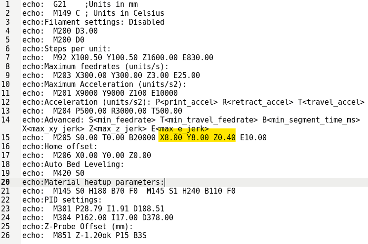
In your slicer software, send the following command to the printer to retrieve the current settings from the firmware:
M503
This will result in all the firmware settings being sent back to the slicer software so you can review them. You want the line that begins with “echo: M92”. After that, you’ll see a series of values after the letters X, Y, Z, and E. The E value is the extruder steps per mm, take note of it. We’ll call this number OGSteps for this procedure.
Measuring actual extrusion of filament
Now that we’ve got the number of steps required to move the filament 1mm, we need to check the actual distance the filament is moved by the extruder stepper motor when instructed to move a specified amount.
To measure the actual distance, you’ll need to first put the printer in relative mode. The following command needs to be sent to the printer to put it into relative mode: M83
Next, you’ll want to issue the command to preheat the printer’s hotend to the temperature appropriate for the filament you will use to perform this test. For the purposes of this article, we’ll use the lowest temperature on the scale for PLA. Send the following command to set the target temperature. M104 S190
After issuing the above command, you’ll need to load the test filament into the extruder and grab your digital calipers, ruler, measuring tape, or whatever device you plan on measuring out millimeters with.
Using your measuring device and permanent marker, measure from the entry point of the filament into the extruder to 110mm and mark it.
Now that you have that measured, you’ll need to send the instruction to extrude 100mm of the filament. The G-Code to send to your printer for this is: G1 E100 F100
This, of course, is supposed to result in 100mm of filament being extruded from the hotend. If that’s how much was extruded, we can move on to the Flow Rate calibration. However, if it’s incorrect, your printer was and is in need of extruder step calibration.
To figure out how much was actually extruded; we can take a measurement of the distance from the filament entry point on the extruder to the mark you made earlier. Take note of this measurement, we’re going to name it RemainFilament. If RemainFilament = 10mm exactly, move on to flow rate calibration (unless you want to perform multiple runs of this test, averaging the results, to ensure a larger data pool and therefore a more accurate determination of actual extrusion distance).
If the distance is not equal to 10mm, your printer has been under or over extruding. Would anyone out the care to share how we know if it’s over-extruding or if it’s under-extruding? No? Ok, well just in case someone way in the back doesn’t know, we’d better explain it. If the measurement is over 10mm, that means the printer is under-extruding. This is resolved by increasing the extruder steps. If the measurement was under 10mm, the printer is over-extruding, which is resolved by lowering the extruder steps.
Calculating the new value for the Extruder Steps
To calculate the proper value for the extruder’s steps per unit a little math will be needed. Luckily, it’s pretty simple math, and as long as you can follow instructions and know how to do variable substitution, you’ll be just fine. To find the actual length extruded: ActualLength = 110-(RemainFilament)
To calculate the new accurate steps per mm: AccurateStepsPerMM=(OGSteps*100)*ActualLength
Now that you have the Accurate Steps Per mm (AccurateStepsPerMM[2]), you’ll want to save that value in the appropriate configuration item in the firmware. Issue the command below, substituting [AccurateStepsPerMM] with the actual value you calculated. M92 E[AccurateStepsPerMM]
You’ll want to save the firmware config changes permanently, which is what the next command is for: M500
You have now completed calibrating your extruder steps. Power cycle your 3D printer and then run the command M503
If everything is correct, continue on to the next section, which will show you how to calibrate your Flow Rate/Extrusion Multiplier. Otherwise attempt setting the Extruder steps again, saving the running-config to memory with M500.
Calibrating Your Flow Rate (a.k.a. Extrusion Multiplier)
The first step to calibrating your flow rate would be to print a test object. The one I typically use for this process is the Classic XYZ 20mm Calibration Cube (available here on Thingiverse). Use the settings listed below for the print.
Vase Mode (single outline, no infill, no top or bottom layer)
Extrusion Multiplier = 1
Extrusion width = width of hotend nozzle
After printing out the cube using the settings above, grab your digital or analog calipers and measure the walls of the cube in multiple places (at least 8 points of measurement should be used) and average those measurements, assigning the value to a variable and name it AverageMeasurement.
Change the extrusion multiplier: NewMultiplier = OldMultipler * (extrusionWidth/averageOfMeasuredWidths)
Repeat this processes until you are content with the output.
You’ve now calibrated your extruder steps and flow rate. On to the next!
Calibrating Filament Diameter
Calibrating your filament diameter should be performed for every print, or at least every time you change filament spools. It’s simple enough to do, and ensures that the correct amount of filament is applied when printing.
Using your calipers, measure the EXACT diameter of your filament in 3 or more places and then average those values.
Enter the resulting value into your slicer settings under filament diameter.
PID tuning your hotend and heated print bed
When to PID Tune
You should perform PID tuning before and after calibrating the printer’s temperatures, as well as anytime you change something physically on the printer such as a fan or even wiring locations. You should also perform PID tuning each time the seasons change, as this affects heating and cooling of the location where your printer is operating.
Why PID tune?
PID tuning keeps temperature fluctuation to a minimum in the hotend and the print bed, which results in better extrusion and reduces the chances of your prints having adhesion issues on the bed.
How to PID tune the hotend
Send the following command to your printer (Substitute [Desired Temperature] with a temp that is safe and preferably one often used.:
M303 E0 C3 S[Desired Temperature]
Example command:
M303 E0 C3 S190
That command will cause your hotend to be PID tuned. On to the next, the print bed
How to PID tune your print bed
Send the following command to your printer, doing the same substitution as you did for the hotend command:
M303 E1 C3 S[Desired Temperature]
Example Command:
M303 E1 C3 S190
Calibrate your temperatures
Calibrating a 3D printer is extremely important if you want it to work properly, and this is especially true for its printing temperature. Every type of filament has a range of recommended printing temperatures. Of all the ways, temperature towers are the most suitable for this purpose.
Sigs of Trouble
If the temperature is too cold, then the layers will not adhere together to each other and parts will not be connected.
Less consistency in texture with colder temperatures.
The filament does not get expelled sufficiently from the nozzle.
Create too soft and sagging parts.
The filament creates prints that will be messy, and stringing will occur.
Discoloration that can occur in the filament.
How to calibrate your temperatures
You’ll need to download a temperature calibration tower from the internet (such as this one from Thingiverse).
You’ll need to change the temperature setting for each section of the tower in the GCode. Insert the M109 command into the GCode at the appropriate line before each section to set the temperature to the next section’s shown temperature on the tower. Change the value next to S to the appropriate temperature: M109 S210
Print the tower and choose the temperature that worked best. Obviously, you’ll want to have confirmed during the print that the temperature actually changed.
2. Read the manual to establish the base temperature and when to change it in the G-Code.
3. Set the base temperature at printing.
4. Set the recommended infill density (10% is the most common one).
5. Go to Extensions, then to Post Processing.
6. Select Modify G-Code, tap on Add A Script and choose Change At Z.
7. Set the Trigger to Height and enter the values ten times. For a 190-240 temperature tower, it should look like this:
Entry Height
1
2
3
4
5
6
7
8
9
10
Height Trigger (in mm)
5
10
15
20
25
30
35
40
45
50
Temperature
235
230
225
220
215
210
205
200
195
190
8. Save the object on an SD card and insert the card into the printer.
9. Run the printer to double-check that everything is fine and pick the optimal temperature.
Calibrating the X, Y, and Z axis
If the number of steps per millimeter are off, you’ll have dimensional accuracies in your prints, such as circles looking like ovals in your prints. Calibrating the axes will correct those inaccuracies.
How to calibrate the X, Y, and Z axis
Retrieve and write down the values for X, Y, and Z’s steps per mm. Use the following command: M503
And look for the line beginning with M92. The values follow their axis in the same line
Print a calibration cube, you should already have one, but if you don’t grab the Classic XYZ 20mm Calibration Cube (available here on Thingiverse).
Measure the X, Y, and Z axis with your calipers, writing down the measurements. If they’re not 20mm on each axis, that axis will need to be adjusted.
Use the following formula to determine the new value of the axis steps per mm E = Expected dimensionO = Observed dimensionS = Current number of steps per mm
(E/O)*S = New number of steps per mm
Once you’ve calculated the new value(s), send them to the printer with the following command (substitute [AXIS][VALUE] with the axis and value you are changing. M92 [AXIS][VALUE]
Other firmware should work but at the time of this document being published, I have only worked with Marlin compatible firmware. ↑
If you didn’t realize that AccurateStepsPerMM was the variable that contains the value for Accurate Steps/mm, I would respectfully submit that maybe 3D printing isn’t for you. (j/k people!) ↑