")
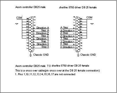
Connection information for acorn controller to Sherline 8760 driver box
The following information is for the connection and configuration of the centroid acorn controller to a Sherline driver box
1. Following parts are needed to make the 25 pin parallel crossover cable need to connect the acorn controller to the sherline 8760 driver box ( step and direction pins are crossed over at the 8760 driver box )
| From Acorn Controller | Axis | To Sherline 8760 Driver Box |
| PIN 1 | Not used | PIN 1 |
| PIN 2 Step | X | PIN 2 Direction |
| PIN 3 Direction | X | PIN 3 Step |
| PIN 4 Step | Y | PIN 4 Direction |
| PIN 5 Direction | Y | PIN 5 Step |
| PIN 6 Step | Z | PIN 6 Direction |
| PIN 7 Direction | Z | PIN 7 Step |
| PIN 8 Step | A | PIN 8 Direction |
| PIN 9 Direction | A | PIN 9 step |
| PIN 10 | N/C | PIN 10 |
| PIN 11 | N/C | PIN 11 |
| PIN 12 | N/C | PIN 12 |
| PIN 13 | N/C | PIN 13 |
| PIN 14 | N/C | PIN 14 |
| PIN 15 | N/C | PIN 15 |
| PIN 16 | N/C | PIN 16 |
| PIN 17 | N/C | PIN 17 |
| PIN 18 | COM | PIN 18 |
| PIN 19 | COM | PIN 19 |
| PIN 20 | COM | PIN 20 |
| PIN 21 | COM | PIN 21 |
| PIN 22 | COM | PIN 22 |
| PIN 23 | COM | PIN 23 |
| PIN 24 | COM | PIN 24 |
| PIN 25 | COM | PIN 25 |
Parts needed
1- Db. 25 pin male acorn controller side of cable
1- Db. 25 pin female 8670 driver box side of cable
Example 1
Parts list
1. Db. 25 pin male connector
2. Db. 25 pin female connector
3. 1 20 foot of 24 or 26 gage wire
4. Solider
Tools needed
Wire stripers
Soldiering tool
Alternate DB 25 pin connector
ANMBEST 2PCS DB25 Solder less Connector, RS232 D-SUB Serial to 25-pin Port Terminal Adapter Breakout Board with Case Long Bolts Nuts (Male + Female
Limit switches
You will need 3 homing switches (4 if you are using a rotary table)
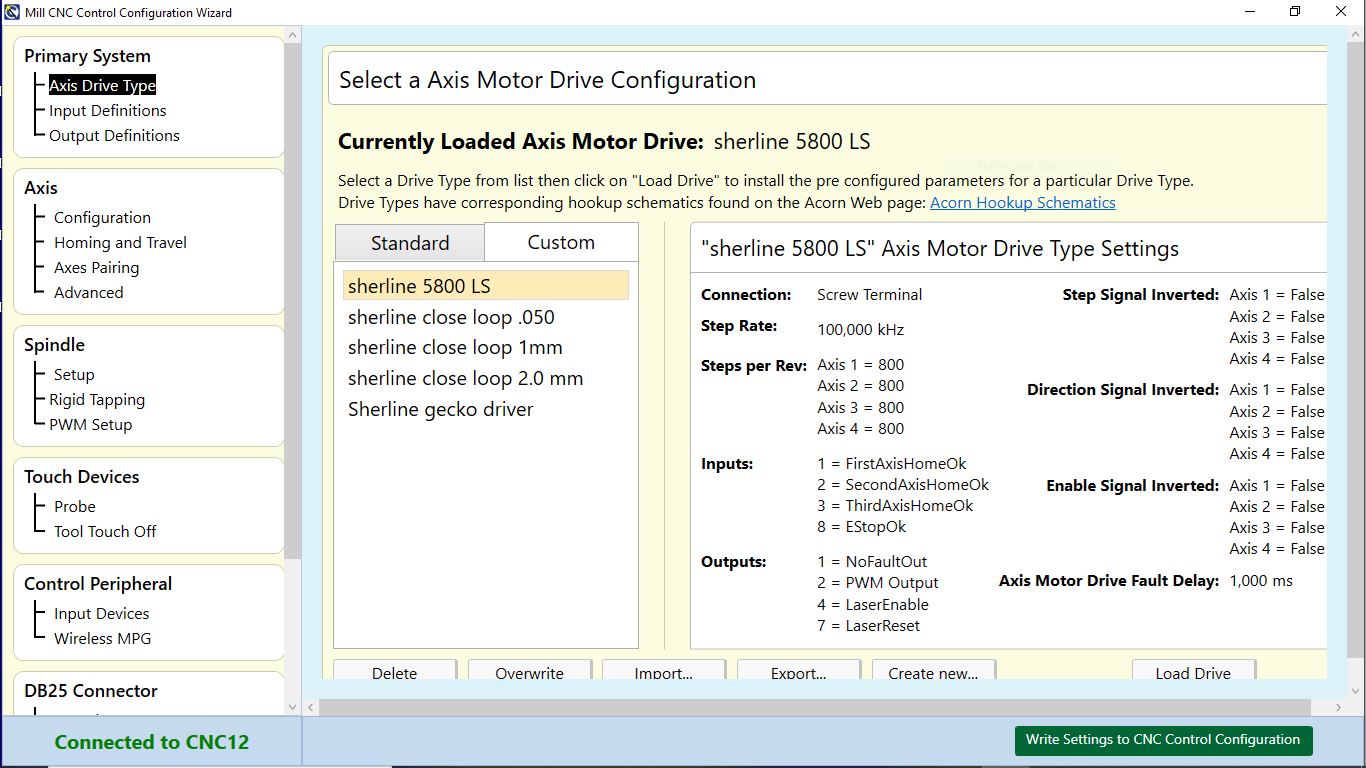
This screen allows you to manage and select and even create “drive types” A “drive type” is a preset
Configuration for a given make and model of axis motor drive. The drive type was created to make configuration
Of the Acorn system easy with its matching schematic. Select the drive type and wire the system according to
The match schematics. By default, a new installation of CNC12 will default to “Bench Test ‘Screw Terminal’ as
The drive type. This is fine for communication bench testing the Acorn with no axis drives connected. After
Passing that test, choose the drive type that matches the axis motor drives that are being employed, click on a
Drive type and click “Load Drive”.
As a convenience, this will pre-populate the IO map and some other screens of the Wizard that match the
Corresponding Acorn to axis drive schematic. The matching schematics are here, use when wiring the control
For the particular drive type being used.
The Acorn Schematic s is found in the All Acorn Documentation thread found here.
Note: While we have tested and provided many different proven Acorn to axis drive schematics and
Next we will configure the acorn cnc mill software a new software configuration
See example below
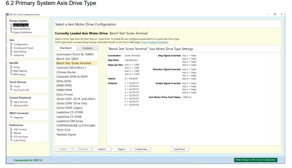
The “Create new…” button will allow you to create a “Custom” Drive type with currently selected settings in the wizard. These Drive Types can be Exported and Imported using the available buttons on screen. Step and direction signals will be present on the Acorn regardless of the drive type selected. However, it is best if we create a drive type that closely matches the drives you are using. You can then work your way down through the Wizard tree to tailor the control to your application.
IMPORTANT: When you have completed any or ALL changes done in the Wizard pages, you must click “Write Settings to CNC Control Configuration” for the changes to take effect.
We will be using the custom tab to configure the acorn cnc mill software with a new software configuration file that will be created.Here I have created a few configurations we will be working the file sherline 5800 LS
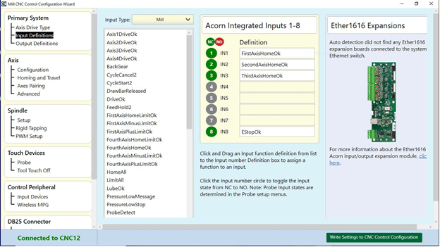
1. Input Definitions
Here we set the input information for our homing switches at H4 and our E-stop at H1. since we connected each homing switch to a input (see example 2) we now need to set the input definitions
Example 2
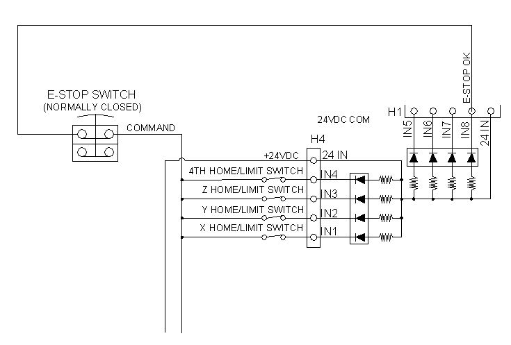
And each homing is connected to an input and all share a common connection, the switch configuration is normally closed. Please see the acorn_ Sherline wiring diagram 1.dwg for a full review of the connection
E-stop is connected to IN8 and command and, the switch configuration is normally closed see the above example 2 and 2A below
NOTE: 4TH axis is for a rotary table in this case we don’t need this connection
Example 2A
3. Output Definitions (also see PWM setup section for configuration of pwm for laser)
1 To select an Output, from the drop down, click on the desired Output, hold and drag it over to the
appropriate Output number and drop it.
2 Remove an Output definition by clicking on it and dragging it back to the Output box
Example 3A
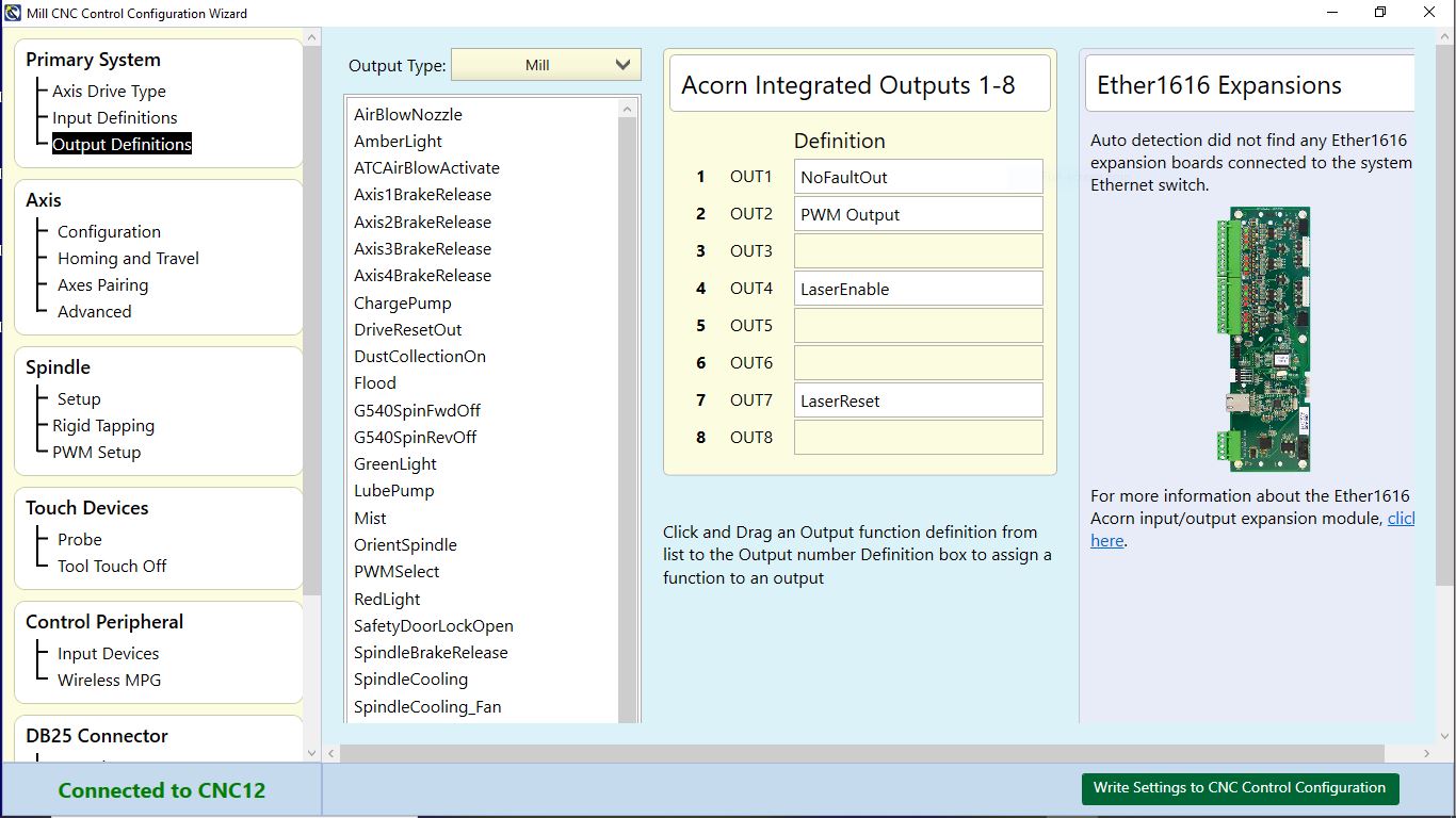
Please select the above Definition from the selection list on left
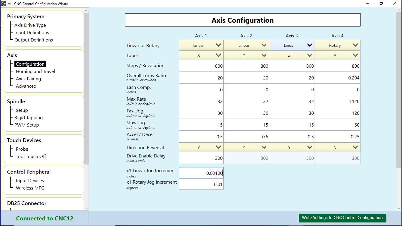
Axis configuration: Here is where we set our axis perimeters
1. The steps/revolution row is 800 steps (because Sherline 8760 driver box is ¼ micro-stepping 1/8 deg /360=200 steps * 4(1/4 micro-stepping) = 800 steps per REV
2.Overall turns- in this row 20 turns per inch ¼-20 lead screw( 1 inch /20turns = .050 per turn of handwheel ,The acorn software requires this data is expressed as the number of turns
3. Max feed rate: for this 8760 driver box max feed rate is 32IMP
4. Fast jog (also known as rapid) 30 IMP, slow jog is15IMP
(note both max feed rate and fast jog setting are before the stepper will skip)
5. Accel/Decel: this setting is how fast in seconds it takes to get up to max feed rate
As stated in the g-code program and how long it takes to slow down
AXIS (Homing and Travel)
Wizard Homing and Travel dialog
In this screen, we will setup how the machine will:
1. Home
2. The directions in which it will Home
3. Software Travel Limits
4. Machine Parking.
HOME PROGRAM:
CNC12 Generates a .HOM file automatically. IF you have a custom .HOM file, then change Home file
to: “Custom User Defined”. Otherwise leave it to the default of Wizard Generated. A “.home” file is simply
a G code program that defines how the machine will “home out” based on the selections made in this
menu.
HOMING TYPE:
1. Select “Simple Homing” if the machine uses no home switches. Simple Home means that the operator
will simply jog the machine to the desired home position and then press cycle start to set home at that
position.
2. Select “Home to Switch” if the machine is equipped with home switches.
3. Selecting “Automatic Homing” will display additional homing options for Automatic Homing.
Homing Direction:
1. If the machine axis must move in the positive direction to seek the home switch, then use +(M92).
1.If it must move in the negative direction to seek the home switch, then use –(M91).
Set Homing Direction for each axis.
Homing Sequence:
1. Sets the order in which the axis is homed.
By default, the order is 3rd axis, 2nd axis, 1st axis, and 4th axis in sequence. This is important,
generally you want to move the cutter away from the table first. So typically the Z axis is first, followed
by the Y axis and then the X axis last. IF the machine is equipped with a rotary axis, and it has a home
switch, that will be last to home.
SOFTWARE TRAVEL LIMITS:
Travel limits are used so that CNC12 knows the usable work envelope of the machine tool use of
software travel limits is strongly suggested in all cases (whether you are using home switches and or limit
switches in any combination)
1. Travel Limit (+) is used if the home switch is on the NEGATIVE end of the axis. The value entered here
would be a positive number. This number is the distance between the home switch and the other end of
the axis travel, typically just shy of hitting a hard stop.
2. Travel Limit (-) is used if the home switch is on the POSITIVE end of the axis. The value here would be
a negative number. This number is the distance between the home switch and the other end of the axis
travel, typically just shy of hitting a hard stop.
For example, the home switch is on the Y Positive end of the travel and there is 12.2” of travel on Y. The value
entered would be -12.2.
PWM Setup menu
The Acorn PWM can be used to command a Laser and/or a PWM Spindle Drive and use the G-code “S function”
(Note: PWM output is not to be confused with 0-10 s command analog output which is used with VFD’s to control 3 phase spindle motors which has its own dedicated output on H8.)
PWM Setup
1. PWM enables
2. Base Frequency (HZ)
3. PWM Command Range 0-100 or 0-1000 this divides up the laser power or spindle RPM by 100 or
1000 increments. For example: AN S command of S1000 would result in max laser power or max spindle RPM when 0-1000 range is selected.
4. PWM Minimum S command power level to start Laser
• Inverse Output
PWM Output for Lasers
a.) 5 volt PWM output signal is on DB25 pin# 14
b.) DB25 pin# 14 is Output 2
c.) PWM is based on 0-100 OR 0-1000 S command. User selects range 0-100 or 0-1000 in Acorn Wizard.
d.) M37 turns ON Laser Output, M38 Turns Laser output OFF: M37 will activate Laser Enable, Laser Reset, and PWM Select. After .5s will turn off Laser Reset.
At this point the laser controller will look at the PWM signal from
OUTPUT2. M38 will wait 30s to allows laser controller to cool, then performs a M95 /37 /38 to turn off both Laser Enable and PW Select.
e.) PWM Velocity modulation feature adjusts the PWM output based on velocity of the machine tool so overturning
Is avoided in the corners or turn around. G37 is used to turn ON and OFF PWM Velocity Modulation.
G37 ON = PWM VM ON, G37 OFF = PWM VM OFF
f.) Simple PWM controls are located in the Acorn Wizard. In addition to “manual PWM controls”, preset buttons