
Testing of different laser drivers from eBay/Amazon
Goodlaser A-11-4 laser driver
405nm 445nm 450nm 520nm 1w 1.6w 2w Laser Diode Driver Circuit Board 12V w/ TTL
Specification Description:
Circuit control: 12V step-down circuit, constant current output (current and voltage are adjustable)
Output specifications: Max 2A
Scope: 200mW-2W 405/445/450 / 520nm red, green and blue laser drive power
Size: 29 * 49mm (width * length), component height with plate 15.5mm
Input voltage: 8-14V
Fig. 1 (upper and bottom parts of the driver)
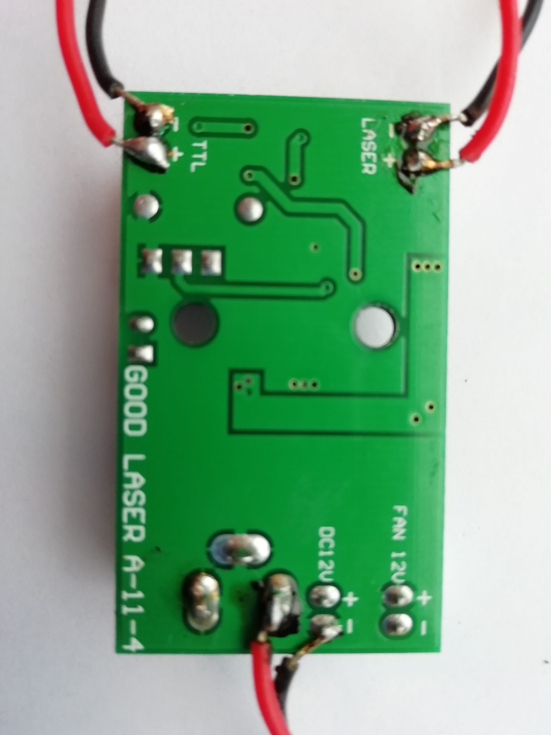
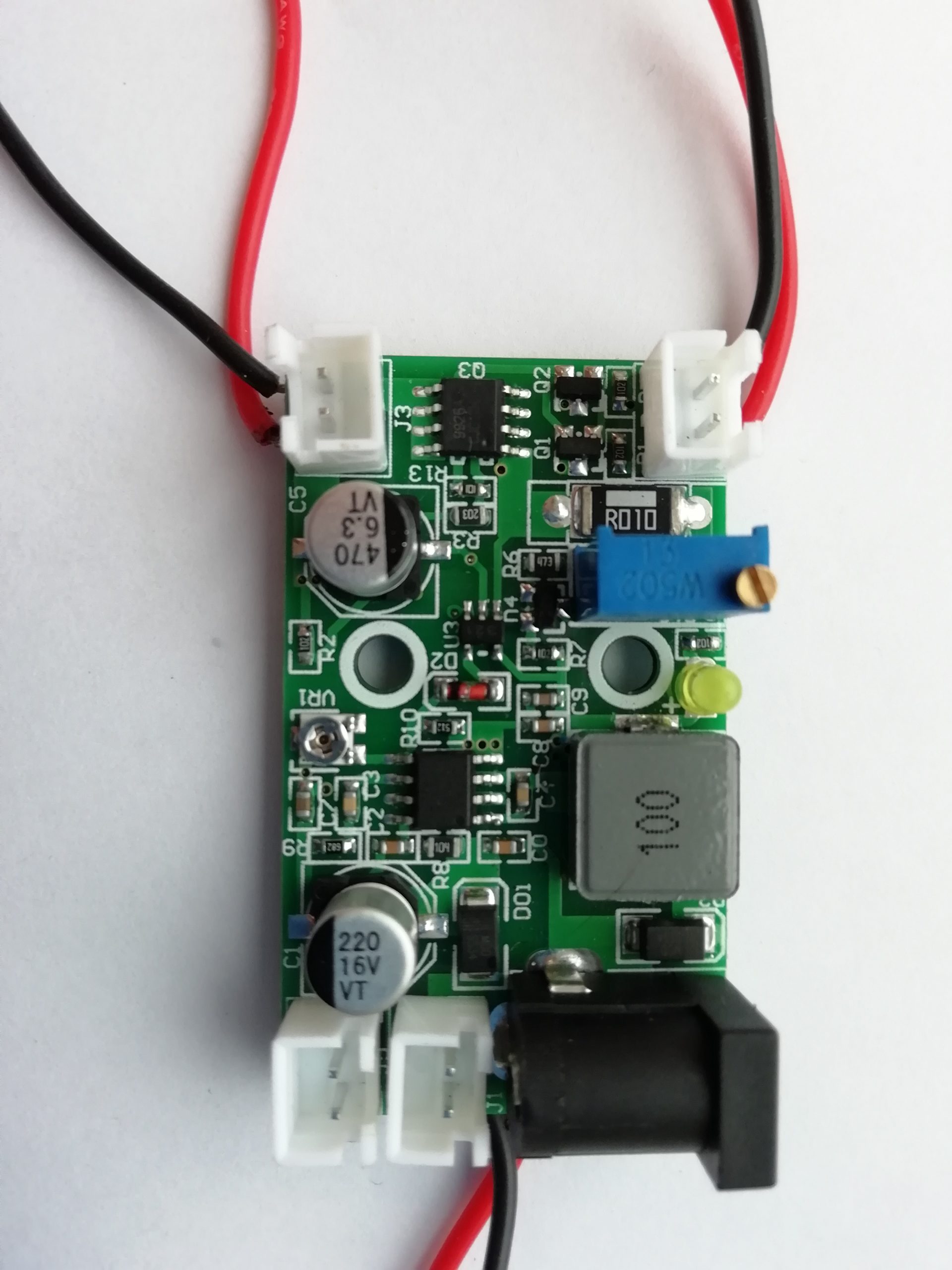
Not a bad variant for low-power lasers. Operates under limiting conditions both from voltage and from
current. Values are set by two tuning registers.
The Vr1 register sets the voltage at the driver output, while a multiturn trimmer sets the laser current.
There’s a feature to connect a 12V fan to the board to cool the laser/driver. Via the TTL input it is
possible to adjust the laser power using a PWM signal from the CNC or 3D printer controller.
Table 1 shows the measurement results for the 2A current stabilization mode.
| Good Laser a-11-4(Vin=12V) Ic=2A Uc=9V | |||
| N | R | U | I |
| 0 | 11,2 | 9 | 0,80 |
| 1 | 5,6 | 9 | 1,61 |
| 2 | 3,9 | 8,5 | 2,18 |
| 3 | 3,1 | 5,5 | 1,77 |
| 4 | 2,6 | 4,8 | 1,85 |
| 5 | 2,1 | 4,1 | 1,95 |
| 6 | 1,7 | 3,28 | 1,93 |
| 7 | 1,6 | 2,8 | 1,75 |
| 8 | 1,5 | 2,5 | 1,67 |
| 9 | 1,4 | 2,3 | 1,64 |
Table 1 (Measurements at 2A current stabilization)
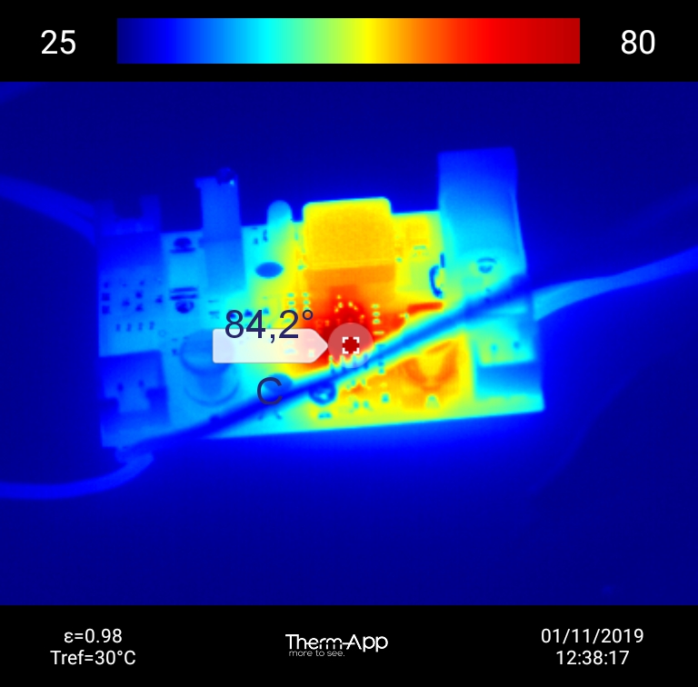
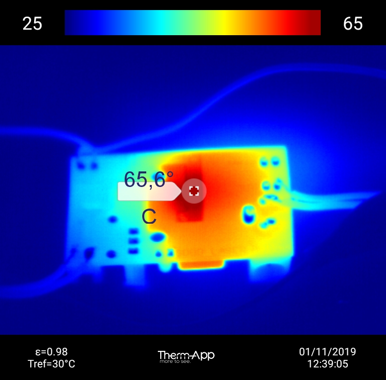
Fig. 2 Fig. 3 (The temperature of the upper and bottom parts of the board at 2А)
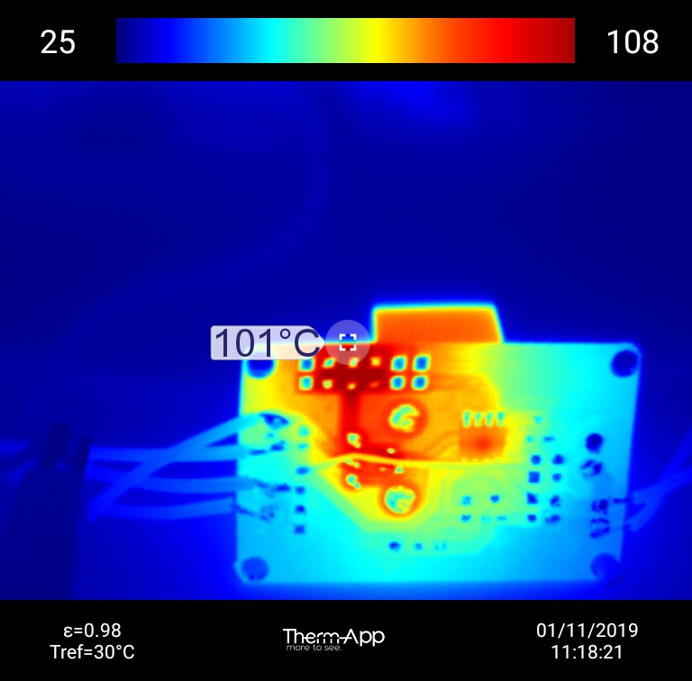
A laser current of 1.5A or less is considered normal for the driver operation. Table 2 presents the current measurements at different load resistance. Fig.4 and 5 shows the board temperature at 1.5A load current.
| Good Laser a-11-4(Vin=12V) Ic=1.5A Uc=9V | |||
| N | R | U | I |
| 0 | 11,2 | 9 | 0,80 |
| 1 | 5,6 | 9 | 1,61 |
| 2 | 3,9 | 6,4 | 1,64 |
| 3 | 3,1 | 5 | 1,61 |
| 4 | 2,6 | 4,1 | 1,58 |
| 5 | 2,1 | 3 | 1,43 |
| 6 | 1,7 | 2,4 | 1,41 |
| 7 | 1,6 | 2,1 | 1,31 |
| 8 | 1,5 | 1,9 | 1,27 |
| 9 | 1,4 | 1,8 | 1,29 |
Table 2 (Measurements at 1.5A stabilization current)
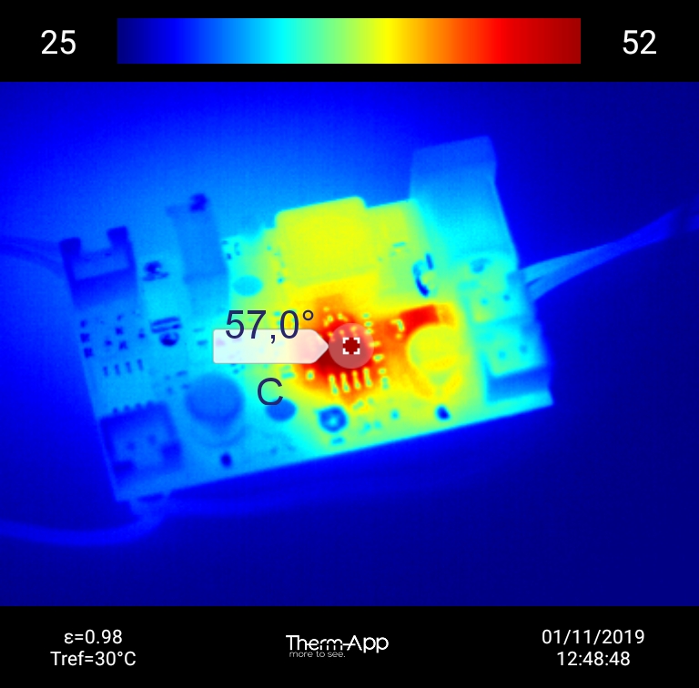
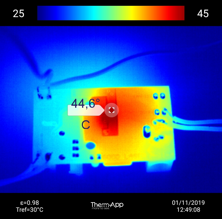
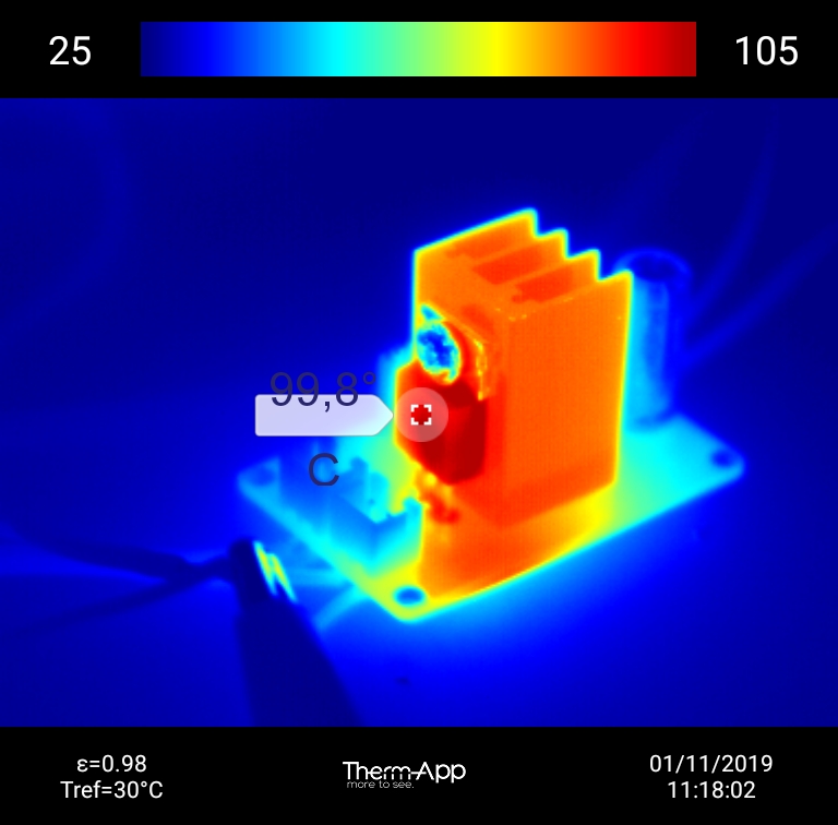
Fig. 4 Fig. 5 (The temperature of the upper and bottom parts of the board at 1.5А)
As it is seen from the test, the optimal condition for the driver operation is the one at a laser current not more than 1.5А.
LD_1,5_V0,2 laser driver
New Laser Diode laser module Driver for (100mW-2W) 445/450nm blue laser+ TTL
Description OF PRODUCTS:
*Suitable for 100mW~2W 445nm/450nm blue laser diode;
*DC9V/12V INPUT;
*Can adjust the resistance, Can set the output current,Maximum current can be set to 2.0A; Attention:Nice working less than 1.6A.


Fig. 1 (upper and bottom sides of the driver)
An LD_1,5_V0,2 is a line current stabilizer made on the microcircuit of an LM358 operational amplifier and an NPN transistor TIP41C.
If you do not take into account the extremely low efficiency and the low operating current values with a standard radiator (you can slightly increase it by making the radiator significantly larger), then this board has better characteristics in terms of the control amount of current, input and output voltage.
Another highlight of the board is the signal inversion at the input EN + and EN-. This means that with the maximum laser power in Gcode, you get the minimum laser power and vice versa.
The best parameters for this board are given in table 1 Figs. 2 and 3 show the temperature at a load current of 1.5A. The low 7V voltage is chosen on purpose because the lower the voltage the less the heat release on the radiator . The voltage below 7V strongly reduces the range of the current adjustment.
| LD_1.5A_V0.2(Vin=7V) Ic=1.5A | |||
| N | R | U | I |
| 0 | 11,2 | 5,8 | 0,52 |
| 1 | 5,6 | 5 | 0,89 |
| 2 | 3,9 | 4,52 | 1,16 |
| 3 | 3,1 | 4,1 | 1,32 |
| 4 | 2,6 | 3,76 | 1,45 |
| 5 | 2,1 | 3 | 1,43 |
| 6 | 1,7 | 2,46 | 1,45 |
| 7 | 1,6 | 2,12 | 1,33 |
| 8 | 1,5 | 1,92 | 1,28 |
| 9 | 1,4 | 1,8 | 1,29 |
Table 1 (Measurements at a stabilization current of 1.5А and an input voltage of 7V)
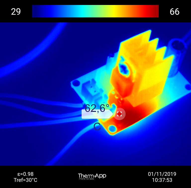
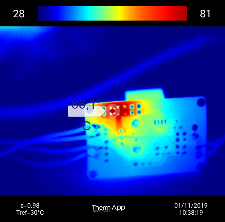
Figs. 2 , 3 (temperature of the upper and bottom sides of the driver at a load current of 1.5А and an input voltage of 7V)
The capabilities of this board can be widened a little by way of connecting a controlling PWM signal to the EN+ and EN- input, so that not to use the laser to full power. Let’s have a close look at the example with a current of 2A and an input voltage of 12V. The measurement values are in table 2
| LD_1.5A_V0.2(Vin=12V)Ic=2A | |||
| N | R | U | I |
| 0 | 11,2 | 10,1 | 0,90 |
| 1 | 5,6 | 8,8 | 1,57 |
| 2 | 3,9 | 6,5 | 1,67 |
| 3 | 3,1 | OH | – |
| 4 | 2,6 | OH | – |
| 5 | 2,1 | OH | – |
| 6 | 1,7 | OH | – |
| 7 | 1,6 | OH | |
| 8 | 1,5 | OH | – |
| 9 | 1,4 | OH | – |
Table 2 (Measurements at a stabilization current of 2А and an input voltage of 12V)
As it is seen from the table, the board was overheated at a load resistance of 3.1Ohm, and further testing was not possible without board damaging. The board didn’t even reach an operational current of 2A.
It is possible to continue measurements, if at the same values to send a PWM signal with a duty factor of 50% (fig.4) to the EN+- input. Table 3 But the board temperature is still too high. Figs. 5 and 6

Fig. 4 (PWM signal at the EN+- input)
| LD_1.5A_V0.2(Vin=12V) Dtc=50% Ic=2A | |||
| N | R | U | I |
| 0 | 11,2 | 11,1 | 0,99 |
| 1 | 5,6 | 10,6 | 1,89 |
| 2 | 3,9 | 8,32 | 2,13 |
| 3 | 3,1 | 6,4 | 2,06 |
| 4 | 2,6 | 5,2 | 2,00 |
| 5 | 2,1 | 4,4 | 2,10 |
| 6 | 1,7 | 3,75 | 2,21 |
| 7 | 1,6 | 3,56 | 2,23 |
| 8 | 1,5 | 3,36 | 2,24 |
| 9 | 1,4 | 3,24 | 2,31 |
Table 3 (Measurements at a stabilization current of 2А and an input voltage of 12V and PWM Duty 50%)
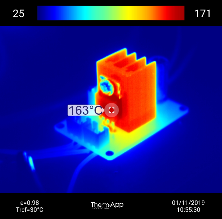
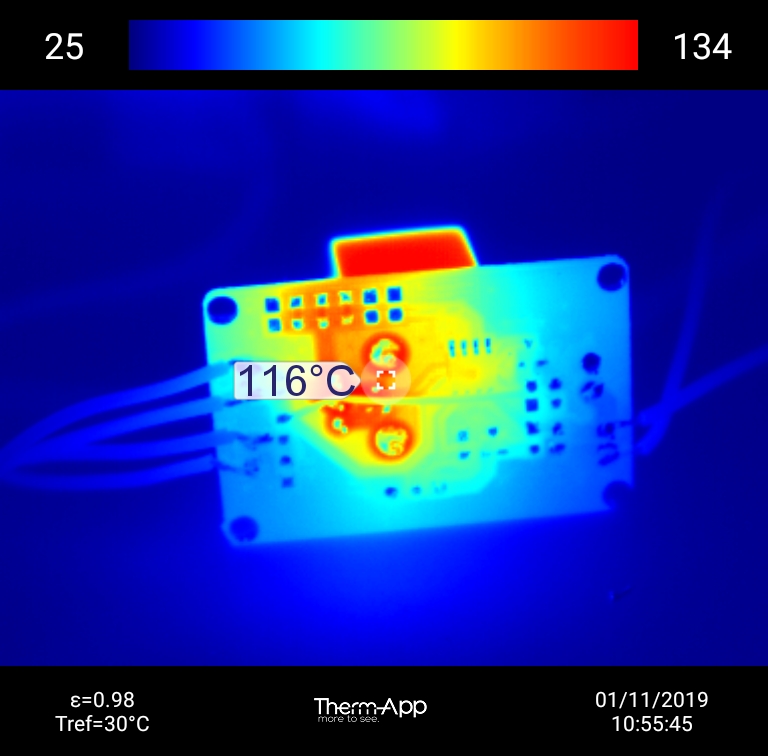
Fig. 5, fig. 6 (the temperature of the upper and bottom parts of the board at a load current of 2А and an input voltage of 12V, Duty 50%)
As the result of the experiments we managed to set the load current at 3.5А(it’s enough for a 5W laser),with a voltage of 12V, but a PWM duty of only 20%. Fig. 7 The measurements results are in table 4 The board temperature is in figs. 8 and fig.9

Fig. 7 (PWM signal at the EN+-input)
| LD_1.5A_V0.2(Vin=12V) Dtc=20% Ic=3.5A | |||
| N | R | U | I |
| 0 | 11,2 | 11,4 | 1,02 |
| 1 | 5,6 | 10,9 | 1,95 |
| 2 | 3,9 | 10,3 | 2,64 |
| 3 | 3,1 | 9,9 | 3,19 |
| 4 | 2,6 | 9,5 | 3,65 |
| 5 | 2,1 | 7,6 | 3,62 |
| 6 | 1,7 | 6,4 | 3,76 |
| 7 | 1,6 | 5,8 | 3,63 |
| 8 | 1,5 | 5,4 | 3,60 |
| 9 | 1,4 | 5 | 3,57 |
Table 4 (Measurements at a stabilization current of 3.5А and an input voltage of 12V and PWM Duty 20%)
Figs. 8 and 9 (The temperature of the upper and bottom sides of the board at a load current of 3.5А and an input voltage of 12V, Duty 20%)
Thus, this board is the most compliant when choosing a power supply source for a lower power laser (and for a more powerful laser in an pulse mode). But it’s worthwhile taking into account a low efficiency coefficient, signal inversion and an urgent need to refine the standard cooling system.
TF-DZ-1.2 laser driver
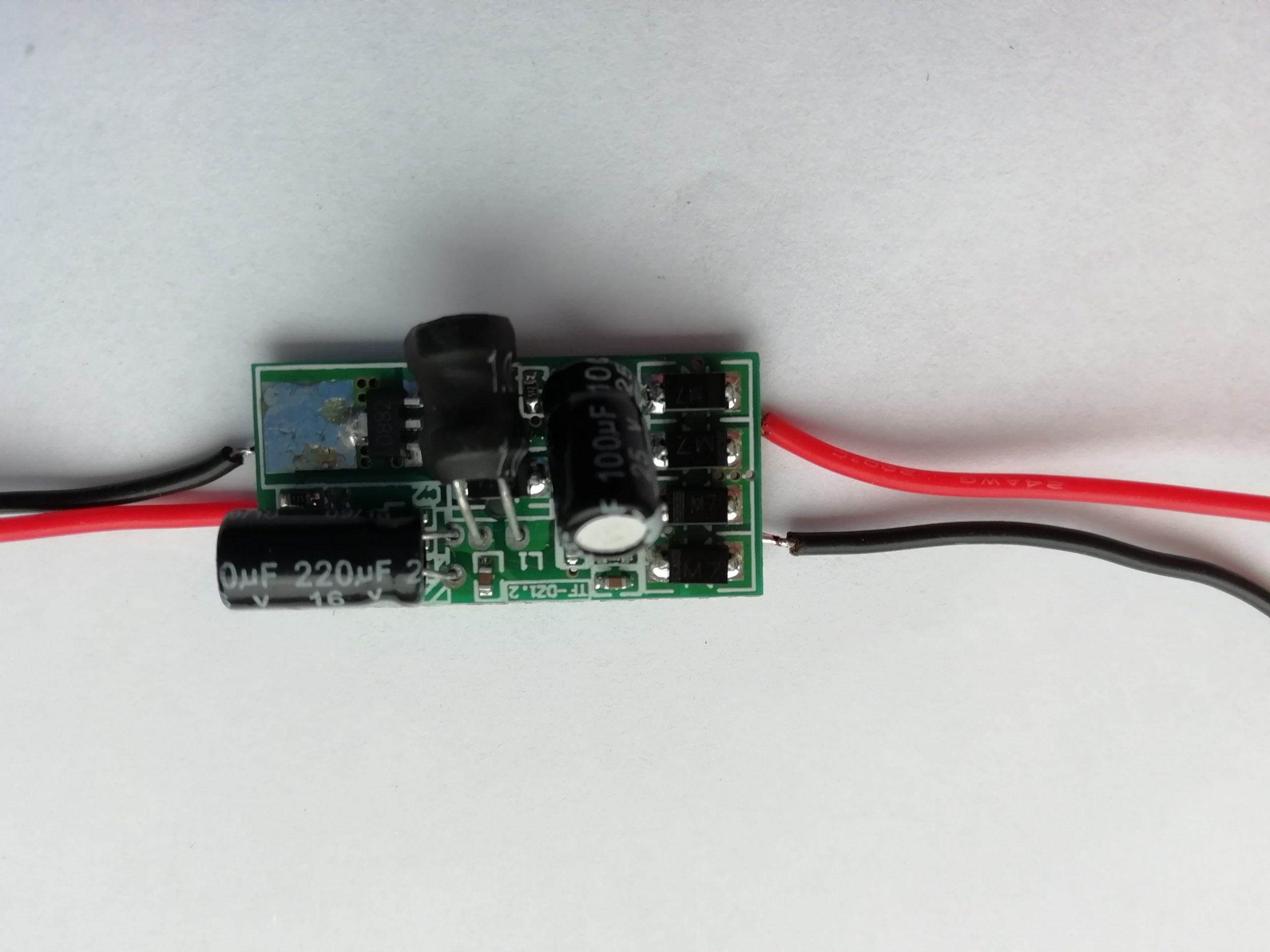
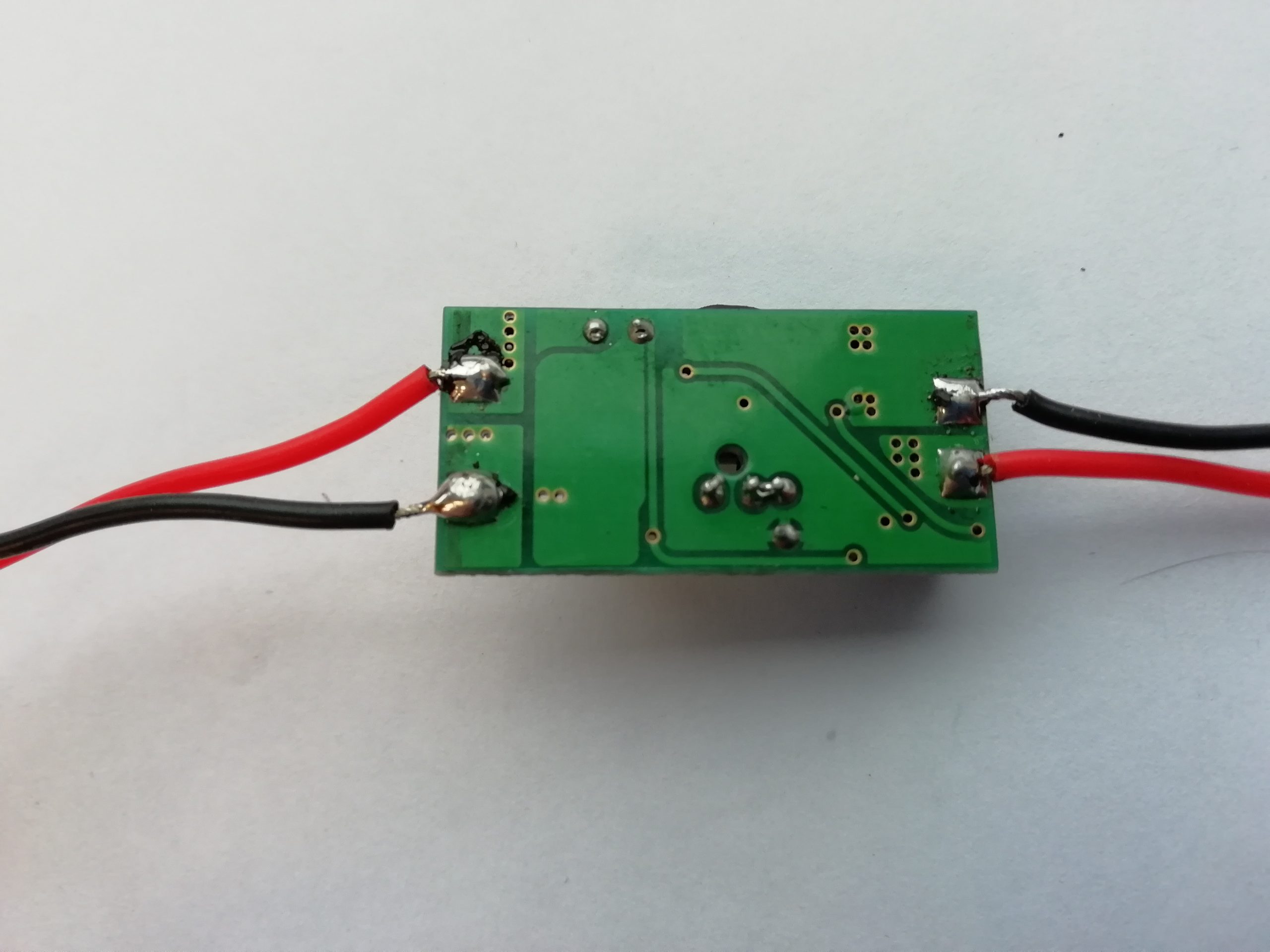
Fig. 1 (upper and bottom parts of the driver)
The presented driver has neither settings nor input to control the laser power with a PWM. The driver has a stabilization DC of around 350mA (0,35A) and can be used to feed low-power lasers. Gets too hot.
Measurements results in a presented in table 1 The driver temperature is shown on fig. 2 and 3
| TF-DZ1.2(Vin=12V) | |||
| N | R | U | I |
| 0 | 11,2 | 4,28 | 0,38 |
| 1 | 5,6 | 2,15 | 0,38 |
| 2 | 3,9 | 1,47 | 0,38 |
| 3 | 3,1 | 1,12 | 0,36 |
| 4 | 2,6 | 0,92 | 0,35 |
| 5 | 2,1 | 0,71 | 0,34 |
| 6 | 1,7 | 0,6 | 0,35 |
| 7 | 1,6 | 0,53 | 0,33 |
| 8 | 1,5 | 0,49 | 0,33 |
| 9 | 1,4 | 0,46 | 0,33 |
Table 1 (Stabilization DC measurements 0.35А)
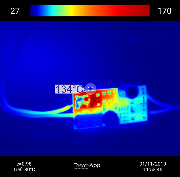
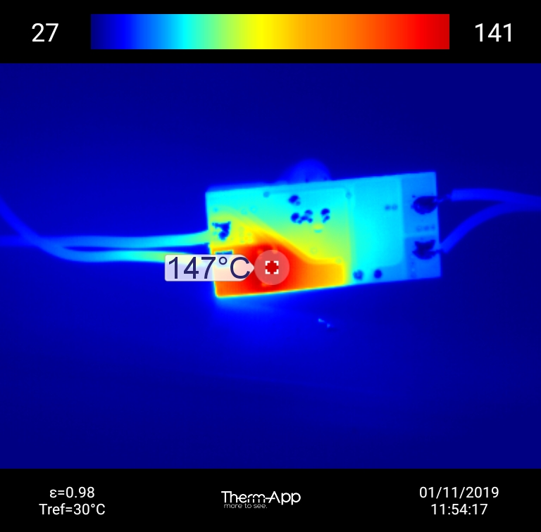
Fig. 2 and fig. 3 (the temperature of the upper and bottom boards at 0.35А)