Introduction to CNC for a Total Novice Getting Started
Part of a series by Graham Bland
Contents
- Change
- Introduction
- My Background
- Disclaimer
- Accompanying files
- 3018-PRO Specifications
- Assembling your router
- Checking it out
- Sanity check on the Router settings
- Recovering your settings
- Are the axes connected correctly and move in the correct direction
- Troubleshooting
- Changing the direction of movement on an axis
- Distance travelled by each axis
- Key Router settings affecting setup of your machine
- $30 and $31 – Max and Min Spindle Speed (RPM)
- $110, $111 and $112 – Maximum speed of movement on the Axis.
- $32 – Laser Mode
- TRYING IT OUT
- Mounting the Stock
- Mounting the bit
- Positioning the bit
- Pressing the Buttons
- Some background and terms – (In no particular order)
- Units
- Controller or Motherboard
- Grbl
- Mach3
- Stepper Motor
- Microsteps
- Missed Steps
- PWM (Or TTL)
- Spindle Motor
- Bed
- Tool Holder
- ER11 Tool holder
- Bit (or Tool) Introduction
- Stock
- Tabs
- Tiling
- Spoilboard/ Baseboard / Wasteboard
- GCode
- Toolpath
- Limit Switches or End Stops
- Coordinate systems
- Home/Machine coordinates
- Safe Position
- Work Coordinate System (WCS)
- Examples
- Absolute vs Relative Coordinates
- Jogging
- Stock
- Feed
- Speed
- Passes
- Z-Probe
- Height Map
- Vref 30
- Offline Controller
- The Process
- Talking to the router
- CAM (Computer Aided Manufacturing) Process
- CAD (Computer Aided Design) Process
- Welcome to The Real World!
- Bits in more detail
- Bit Types
- Software
- Maintenance
- What to do next
- Acknowledgements
Changes
From V1.0
- Stripped out the Laser bits into a separate document
- Tried to make it a bit less rambling and more linear
- Added Assembly hints and post assembly checks
- Expanded and added Examples for coordinate systems
- Updated and expanded due to learning and understanding more as I progress
From V2.0
- Corrected the section “Changing the direction of movement on an axis” which had instructions for the X and Z axes reversed. (My thanks to Anthony Drake for pointing this out)
Introduction
If you are a novice this is for you, if not then there may be bits of interest, if you know what you are doing any comments would be welcome!
My apologies for this but when I started this was a series of five pages of notes I had made when starting out as a total novice. Now It’s 30+ pages because as I keep on learning there is more to add!
A while ago I decided to take the plunge and I purchased a SainSmart Genimitsu 3018-PRO with a 2.5W 450nm Laser module and a full set of bits from SainSmart. I later upgraded to a 5.5W Laser.
Any comments or specific examples refer to my SainSmart Genimitsu 3018-PRO using the Grbl system, although a lot does apply to other models, yours may be different. A lot of information is anecdotal and based on reading the forums and from the internet.
But I do hope this series is useful for anyone using any hobbyist CNC router for the first time.
There are other suppliers selling under the same name of 3018, 3018-PRO These, while looking
and sounding the same will differ in the details, the router motherboard being different, if an adjustable collet is fitted to the Spindle. The 3018 simply means 30cm x 18cm dimensions of the
bed, without the spaces, cm and x, just the travel on the X and Y axis. There are other variants such as 2415 which follow the same naming conventions.
I am using free to use software here by preference (Apart from Windows of course). NOTE: I mean free to use for me as a non commercial hobbyist, for example I am using Autodesk Fusion360 and have a free licence as long as I don’t try and make any money out of it, that’s fine as a full licence would be hundreds of pounds a year and it’s a hobby. Any software which has a free version and a subscription version, well I am referring to the free one unless specified.
I am producing this as a document, mainly because It is an edited series of notes I made, partly because I am tired of watching instructional videos on YouTube which play at Mach 2 and so I am constantly stopping, rewinding and re-watching. Also I have been told I have a body made for Radio, a voice most suited to the Deaf and I still haven’t worked out how to use the video camera on my phone properly.
My Background
- I am a retired IT guy, started as a trainee programmer using an IBM 360/40 a long, long time ago (the /40 designation meant it had a 40k memory, massive at that time).
- Until recently if I wanted to design something I would use pencils, paper, compass and ruler.
- I did get 98% on my last woodwork exam and the table I made is still in use, but that was an even longer, long time ago.
- Always been keen on making things and trying to understand how things work.
Disclaimer
Yeah nowadays it has to be included, and it makes sense as I accept NO liability for anything I may say, write or think.
- I am a total novice (or was when I started out). I MAKE NO CLAIM THAT ANYTHING I SAY IS CORRECT! All this is based on searching the Internet, forum comments and my own experiences.
- If you have and are using a Laser module, even the lowest powered is powerful enough to destroy your vision completely, and that of any pets, children, spectators etc. SO EXCLUDE THEM AND USE THE GOGGLES!
- These are power tools, sharp pieces of metal designed to cut things while rotating at high speed and throwing small bits away also at high speed. Keep everybody’s fingers out! A wood chip flying up your nose is nothing to be sneezed at, never mind in one of your eyes.
- Take account of the materials you are using and take adequate precautions, dust and ashes can be harmful.
- I work in mm. Why anyone still uses inches for design work is a mystery. But then I still think of temperatures in Fahrenheit, anything beyond 500m in miles and property plot sizes in acres!
- I have been told by lots of people that my sense of humour is at the least a bit strange. I do not apologise for it.
- Any corrections, clarifications or discussion welcome. You can find me on the Facebook SainSmart Genmitsu CNC Routers Group as Graham Bland. https://www.facebook.com/groups/SainSmart.GenmitsuCNC/
Accompanying files
NOTE: Facebook has a problem, it will not allow compressed (.zip, .gz, ) to be uploaded to the
Files section of any group, but it bases this decision solely on the file extension, not the contents.
It is easy to bypass this by changing the file extension before uploading, I use .zip files, and rename them to .zipp This means that after downloading you will have to reverse this by renaming any xx.zipp file to xx.zip, windows will issue warnings that you are probably going to make the file unusable, just ignore it and rename anyway. Then you can open and extract the files as you wish.
So you there may be 2 versions in the files section. One an xx.pdf which is the basic words, and if there are any accompanying files with it an xx.zipp the .pdf and everything else.
Accompanying files for this section are:
| BitPositioner.pdf | A sheet of bit positioning aids as a PDF |
| SingleBitPositioner.jpg | Picture of one bit positioning aid |
3018-PRO Specifications.
Derived from a number of sources, but as far as I can determine, at the time of writing.
NOTE: Specifications can and will change, to be honest some values are just my best guesses.
| X Travel (mm) | 300 |
| Y Travel (mm) | 180 |
| Z Travel (mm) | 45 |
| Bed Size X (mm) | 290 |
| Bed Size Y (mm) | 180 |
| Resolution X (mm) | 0.01 |
| Resolution Y (mm) | 0.01 |
| Resolution Z (mm) | 0.01 |
| Max Feed Rate X (mm/min) | 1000 |
| Max Feed Rate Y (mm/min) | 1000 |
| Max Feed Rate Z (mm/min) | 1000 |
| Router bit Holder | ER 11 |
| Std bit Shank (mm) | 3.175 |
| Min bit Shank (mm) (Requires collet set) | 1 |
| Max bit Shank (mm) (Requires collet set) | 7 |
| Spindle Motor | Brushed, Type 775 |
| Max Spindle Speed (RPM at 24V No Load) | ~8,500 |
| Max Torque (N/m) | 0.2 |
| Supply (V) | 24V (on this router) |
| Stepper Motors | Nema 17 Bipolar |
| Rotation Degrees per step | 1.8˚ |
| Steps per rotation | 200 |
| Torque (Nm) | 0.25 |
| Supply (V) | 12 |
| Current (A) | 1.3 |
| Max RPM (Depends on Motor controller) | 500 |
| Threaded screws (mm per rotation) | 2 |
| Laser 2.5W and 5.5W | |
| Type | Blue Diode |
| Frequency nM | 450 |
| Recommended Focal Length mm | 50 |
One thing to remember, these are hobby machines, inexpensive hobby machines, the main drive for the development of CNC is commercial manufacturing. If you are expecting to spend £200 on a router you cannot really expect the same construction, tolerances and features you would get if you were spending £2,000 or £20,000 on the machine. But the principles involved are the same.
Assembling your router
I’m not really going to get far into this as there are loads of YouTube videos and other tutorials available, apart from a couple of hints.
These machines change in the details over time, to improve the quality, solve problems and decrease the costs, so the video may not exactly match what you have.
- Clean out any swarf from the machining of the holes as best you can.
- Wipe any excess oil from all parts.
- Lubricate the guide rods and threaded screws with a little dry spray lubricant. Routing is a messy business and using a dry lubricant helps stop things sticking to the rods and screws.
- Aligning the Gantry is quite critical, mainly on getting it straight and vertical; my instructions were to make it 46.5mm from the end of the side members, tricky to do using a ruler and square when you get to it.
- Before you assemble the frame take a square and a sharp knife, measure the 46.5mm in from the end and make a small mark on one of them.
- Align the 2 side members on a flat surface one above the other using the square at the ends.
- Take the square and scribe a thin vertical line across them both using the measured mark.
- Make sure the line is at the same end and on the outside when putting in the sides.
- Align the gantry edge to the line on both sides. This ensures it is both at the correct distance and vertical.
- When finally tightening the frame bolts make sure you do it on a flat surface to get the frame as level as you can.
- Things may have more grub screws than the instructions suggest. Loosen and then tighten them all!
- I strongly suggest applying a drop of thread lock to all screws, especially the grub screws to prevent them from vibrating loose over time.
- When tie wrapping the cables make sure they don’t stick up between the frame top and the bottom of the bed, there is not a lot of clearance here, enough for a tie wrap, but not the head of it.
- Instructions may say the Spindle Motor has a red dot on it to show which way it should be connected. A lot don’t have a red dot but have a very faint + mark on one of the plastic dots instead.
- The spindle motor can be a very tight fit! Slacken off the bolt, if it is difficult to fit in then use the end of one of the collet spanners to gently prise it open until you can get the motor in.
- Align the top of the sleeve around the motor with the top of the motor bracket before tightening it up. This seems to be a good starting position.
- Do check that all the axes move freely to their limits in all directions without binding by turning the threaded rods manually (without any power connected to the router).
Checking it out
These are some simple checks to make once assembly is complete, but before you have tie wrapped or secured all the wiring, just in case you need to change any of it.
A lot of suppliers don’t seem to take a lot of care with the default settings on the motherboard (described later), amongst other things these control the direction the axes will move in and how far they will travel. I have never seen examples of a problem with any supplied by SainSmart but quite a few from others.
What we are going to test is:
- Do the settings on the router make sense?
- Are the axes connected correctly?
- Does the spindle turn in the correct direction?
- Is the direction of movement on each axis correct?
- Is the distance travelled by each axis correct?
It is best to start these checks with the spindle above the centre of the bed and at the midpoint on the Z axis, manually adjust it by turning the threaded rods before powering on for the first time.
Install Candle on your computer, it should be supplied with your router but if not you can download it for Windows from http://s3.amazonaws.com/s3.image.smart/download/101-60- 280PRO/Grblcontrol%28Candle_1.1.7%20%29.zip or https://github.com/Denvi/Candle/releases Extract and install. NOTE: There is a later release than 1.1.7, version 1.2b but at the time of writing this is still a pre-release version.
Connect the computer to the Router via the USB cable and plug it in.
Start Candle and connect to the Router, it should find it automatically, if not click on Service/Settings you can select the Com Port there.
You should see something like this from Candle 1.17:
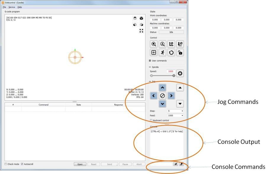
The first thing to do is to type $$ in the Console command box and send it by hitting the enter key. This will display in the console output all the Grbl settings values from the router. Copy these into a text editor and save the file somewhere as a baseline. No matter how much you may mess up the settings you will always then have a previous set to go back to.
You will see the response to the $$ command as a list of $99=xx lines where 99 is the setting number and xx is the current value.
To change a value send the command of $99=xxx where 99 is the setting number and xxx is the value. These are permanently stored on the motherboard so they only need to be changed once.
Sanity check on the Router settings
Some suppliers, well let’s just say they don’t believe in quality control a lot. I have seen many examples where some of the router settings are crazy.
The motherboard has a series of settings on it; these allow it to be used on different routers, different stepper motors, different wiring etc. Nearly all of these should be static, set once at the factory to suit the router and then forget they are there, but for example if you were to add limit switches to enable home positioning or to buy a replacement motherboard, which is not set up for your specific router some of them would have to be changed.
Remember there is no correct answer, some routers and motherboards are different, new versions are developed which means these can change over time but a quick sanity check of the important ones makes sense. I have listed the settings and given a range which I think they should be in or a suggested value.
NOTE: If I say something should be 0.01 ish and your default settings are for example 0.05 or 0.02 don’t worry. If your default value is something like 25483.72 then it is almost certainly wrong! If the Range says ‘Only’ and your value is different then it is wrong (probably)!
The default settings and values for my 3018-PRO with a Woodpecker CamXTool 3.4 motherboard :
| Applies only if using Soft Limits in conjunction with limit switches | ||
| Applies only if using limit switches | ||
| Default Setting | Description (The links will take you to the relevant page for Grbl 1.1) | Range |
| $0=10 | Step pulse, microseconds | 3-15 ish (only the 15 is ish) |
| $1=25 | Step idle delay, milliseconds | 15-30 ish OR 255 |
| $2=0 | Step port invert, mask | Only 0-7 |
| $3=2 | Direction port invert, mask | Only 0-7 |
| $4=0 | Step enable invert, boolean | Only 0 or 1 |
| $5=0 | Limit pins invert, boolean | Only 0 or 1 |
| $6=0 | Probe pin invert, boolean | Only 0 or 1 |
| $10=1 | Status report, mask | Only 0-3 |
| $11=0.010 | Junction deviation, mm | 0.1 to 0.001 ish |
| $12=0.002 | Arc tolerance, mm | 0.1 to 0.001 ish |
| $13=0 | Report inches, boolean | Only 0 or 1 |
| $20=0 | Soft limits, boolean | Only 0 or 1 |
| $21=0 | Hard limits, boolean | Only 0 or 1 |
| $22=0 | Homing cycle, boolean | Only 0 or 1 |
| $23=0 | Homing dir invert, mask | Only 0-7 |
| $24=25.000 | Homing feed, mm/min | 10-50 ish |
| $25=500.000 | Homing seek, mm/min | 250-750 ish |
| $26=250 | Homing debounce, milliseconds | 5-50 ish Yes I know my default setting is wrong but it is not used. |
| $27=1.000 | Homing pull-off, mm | 0.5-3.5 ish |
| $30=1000 | Max spindle speed, RPM | 750-7500 ish |
| $31=0 | Min spindle speed, RPM | 0-100 ish |
* These values ($100-102) should all be the same. If only 2 are the same set the third accordingly. Other values are possible but 800 or 1600 are overwhelmingly common for this sort of router. However the tests you are going to run check these settings.
| $32=0 | Laser mode, boolean | 0 or 1 1 ONLY when using a laser |
| $100=800.000 | X steps/mm | 800 or 1600* |
| $101=800.000 | Y steps/mm | 800 or 1600* |
| $102=800.000 | Z steps/mm | 800 or 1600* |
| $110=1000.000 | X Max rate, mm/min | 500-2000 ish |
| $111=1000.000 | Y Max rate, mm/min | 500-2000 ish |
| $112=600.000 | Z Max rate, mm/min | 500-2000 ish |
| $120=30.000 | X Acceleration, mm/sec^2 | 20-10000 ish |
| $121=30.000 | Y Acceleration, mm/sec^2 | 20-10000 ish |
| $122=30.000 | Z Acceleration, mm/sec^2 | 20-10000 ish |
| $130=200.000 | X Max travel, mm | Around your router size ish |
| $131=200.000 | Y Max travel, mm | Around your router size ish |
| $132=200.000 | Z Max travel, mm | Around your router size ish |
If you changed anything I suggest you keep a record of it as well as your original settings.
Recovering your settings
Normally you can reset the machine to its factory settings by sending it:
$RST=$ to erase and restore the $$ Grbl settings back to defaults, which is defined by the default settings file used when compiling Grbl.
Your board manufacturer can disable these commands. And if you have changed anything your changes will be lost! If some of the settings were wrong to start with then these commands will restore all the wrong settings as well. But you can’t have everything!
Are the axes connected correctly and move in the correct direction Set the step value in the jog commands area in Candle to 10 using the Step dropdown list, this sets how far the spindle will move in mm each time you click on a jog button, it needs to be something you can see but not move it so far it reaches the edges.
All movements on the axes are the spindle relative to the bed looking from the front. The left and right arrows should move the spindle left and right respectively, the X axis. Up and Down Buttons should move the bed forwards (the bed moves, not the spindle but the spindle gets closer to the top of the work), towards the front, or backwards, away from the front respectively, the Y axis. The two buttons on the right of the Jog commands should move the spindle height up and down respectively, the Z axis.
Lastly in the box above the jog commands set the spindle speed to something like 10 then click on the ‘Circular saw’ icon this should turn the spindle motor on and off.
When turning it should be rotating in a clockwise direction, you should be able to see the direction of rotation if you can’t tell carefully hold a piece of card to an edge of the tool holder and see which direction it is tugged in.
Hopefully everything works as expected but if not:
Troubleshooting
| Problem | Possible Solution |
| Spindle rotates in the wrong direction | Swap the two wires over on the top of the spindle motor. |
| The wrong axis moves | Check the connections from the stepper motors and make sure they are plugged into the correct X Y and Z axis connection on the router board. |
| One or more axes move in the wrong direction | This needs a change in the motherboard settings as described below. It is almost certainly NOT a wiring problem. |
| An axis does not move at all |
just to be sure. |
Changing the direction of movement on an axis
If anything is moving in the wrong direction then you need to change one of the settings, namely $3, the direction port invert mask to be precise. This is very easy to do.
This is what is known as a bitmask, the low order 3 bits are used to control the directions the axes move (ZYX). Convert the original value of $3 to binary, flip the appropriate bits for any axis moving in the wrong direction and convert back to a decimal number. (the decimal value will always be between 7 and 0 inclusive).
OR use the following table: Select the row for your current $3 value, go across to the column for the Axis to change and the value there is your new $3 value.
NOTE: THIS ONLY ALLOWS YOU TO CHANGE ONE AXIS AT A TIME. If you need to change more than one make multiple passes through the process.
| New $3 Value | |||
| Current $3 Value | Invert Z | Invert Y | Invert X |
| 0 | 4 | 2 | 1 |
| 1 | 5 | 3 | 0 |
| 2 | 6 | 0 | 3 |
| 3 | 7 | 1 | 2 |
| 4 | 0 | 6 | 5 |
| 5 | 1 | 7 | 4 |
| 6 | 2 | 4 | 7 |
| 7 | 3 | 5 | 6 |
Examples:
Current $3 value is 2 and the X axis needs inverting.
Select the 2 row and the X column, the new $3 value is 3.
Current $3 value is 3, and the Y and Z axes need inverting.
To invert the Y axis select the 3 row and the Y column, the new $3 value is 1. To invert the Z axis select the 1 row and the Z column, the new $3 value is 5.
In Candle type $3=x in the console command box where x is the revised number and hit enter to send it to the router.
If anything has failed or been changed repeat the tests, everything should now be moving in the correct direction, if not repeat the above until it does.
If you changed any settings make a note in your file containing your original settings just in case.
Distance travelled by each axis
The movement is controlled by the $100, $101 and $102 parameters. Look at the values you got back from the $$ command.
- These values are the number of microsteps required to move the spindle on each axis by 1mm, $100 sets the X axis, $101 – Y, $102 – Z.
- These should all be the same, I have never heard of a machine like this using different values for $100,101 and 102. It would be possible to design and build one but as long as your stepper motors look the same on each of the axes and the threaded rods look the same it is almost certain they should all be the same.
- They are almost certainly going to be whole round numbers.
- NOTE: because of the standard components that tend to be used the likely values on a 3018 are going to probably be 800 or 1600. 324.6 or anything similar is almost certainly going to be wrong.
What they tell the motherboard is how many microsteps it has to turn the threaded rod on the axes to move the spindle 1mm. If they are not all the same then the first step is to send
$101/2/3=800/1600 commands to make them all the same (Hint: If two of them are 800 or 1600 select that value!).
Now they are all the same we only need to check one value, I select the X axis.
- Take a piece of paper, tape, ruler, use a pencil on the bed or just eyeball it.
- Mark 2 points 10mm apart (10 is not a magic number but it works well) (Make sure you have 10mm of travel available to the right first)
- Using the jog commands (or move the paper/ruler etc.) position the spindle over the left hand mark.
- Now set the jog step to 10mm
- Jog right once
- The spindle should now be over the second mark.
You are not looking for if it moves 9.9mm instead of 10mm, if it is out it is much more likely to be a gross error, moves 5mm or 20mm instead of 10mm. Estimate how far out it is, if has only got ½ way there then your $100 value should be doubled, if it travelled twice as far as it should then your $100 value should be halved, remember 800 and 1600 are the common values.
I would then suggest a quick visual check by jogging all the axes by 10mm and making sure the distance travelled looks like 10mm.
CONGRATULATIONS! Your router is now initially set up!
Key Router settings affecting setup of your machine
$30 and $31 – Max and Min Spindle Speed (RPM)
First on these machines this is not actually the RPM of the spindle, the board does not get any feedback on the actual speed so can’t tell and adjust the speed. It’s just a range of power using PWM sent to the spindle motor or laser. This is not an exact linear mapping (500 would be half power, not the same as half speed). Let’s just say bigger values make it go faster and smaller values make it go slower. If you send a spindle speed command which is greater than the value of $30 then $30 will be used instead, so setting a speed of S2500 followed by S1500 is translated into actual speeds of S1000 followed by S1000.
I don’t have the means to measure the spindle speed, this but others have. It seems to be roughly 8,500 RPM not under load!
NOTE: When using a Laser it is important that the value of the Max spindle speed matches any maximum power setting in your software. Earlier versions of Grbl only supported 0-255 as the laser power levels, so you may find your laser software has a max power value of 255. If you have $30 set at 1000 this will mean you are never allowing the laser to be set at more than ¼ power.
The minimum spindle speed. Zero is always treated as off and if the spindle speed is set below the minimum and is not zero the value of $31 will be used instead. I don’t think this really applies to the 3018 series of machines so leave it at 0.
$110, $111 and $112 – Maximum speed of movement on the Axis.
These, set in mm/min, are the maximum speed the spindle or laser will move. If a command sent exceeds them the max value is substituted. Note that although the stepper motors and the threaded rod is the same for all the axes, which should give them the same movement rates, the rate of movement on the Z axis is often set lower. I think this is because if you are moving a bit down they don’t think it should go quite as fast. I can see no other reason why these should be different and they are MAX speeds, your CNC and CAM software should specify these values for the specific job you are doing.
$32 – Laser Mode
This is a Boolean value or on/off, 1 is on (laser connected), 0 is off (spindle connected). If you don’t have a Laser module then just leave this set to 0. If you do then I suggest downloading and reading Introduction to CNC for the Total Novice – Setting up a laser.
I strongly recommend setting Laser Mode On (1) when using the laser module.
I also very strongly recommend setting Laser Mode Off (0) when you use the machine as a router, moving a non rotating bit into a solid surface never produces anything other than nasty grinding noises and potentially damaged bits and stock.
TRYING IT OUT
This is the bit you have probably been waiting for! I know I was.
Oops, still a couple of things to cover but are integral to the trying it out.
I still am unsure if this section should be at the end of this or here, on the one hand is the impatience of wanting to try something new for the first time which places it here! Or the patience to read the rest of the, possibly boring, information which would place it at the end. Impatience Wins!
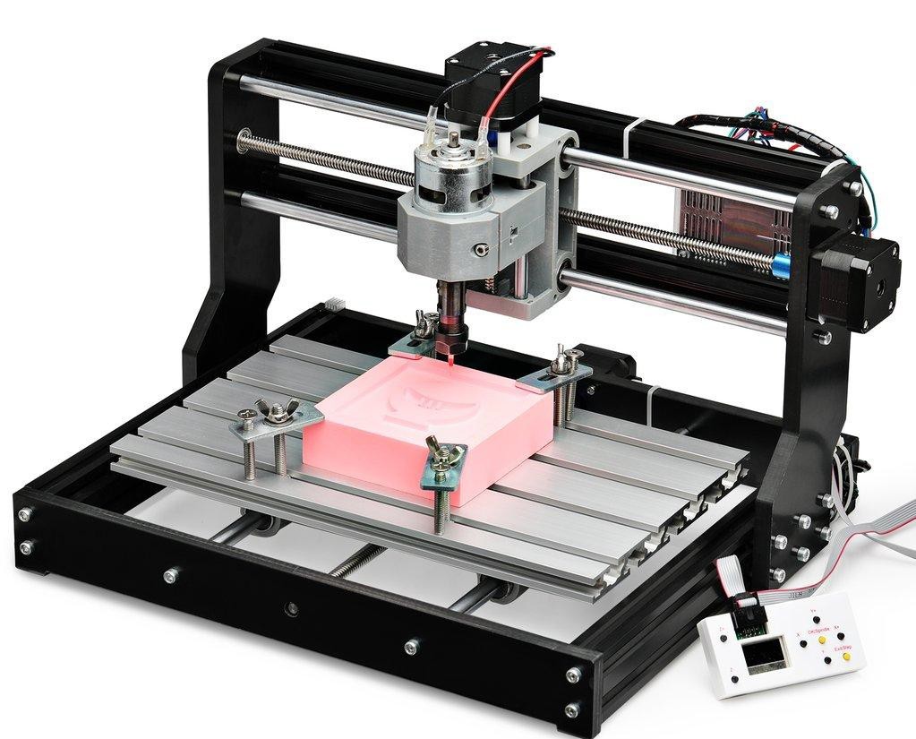
Mounting the Stock
Before letting the bit start spinning you will need some stock, a bit of something to cut. For the first attempt a piece of scrap wood is best, should be at least 10x10cm and over 4mm thick the sample files I provide will only cut to a depth of 1mm or so. What is important is that it is fairly flat and level. You could use other materials but a bit of wood is cheapest and simplest.
Your machine should have come with 4 clamps something like this.
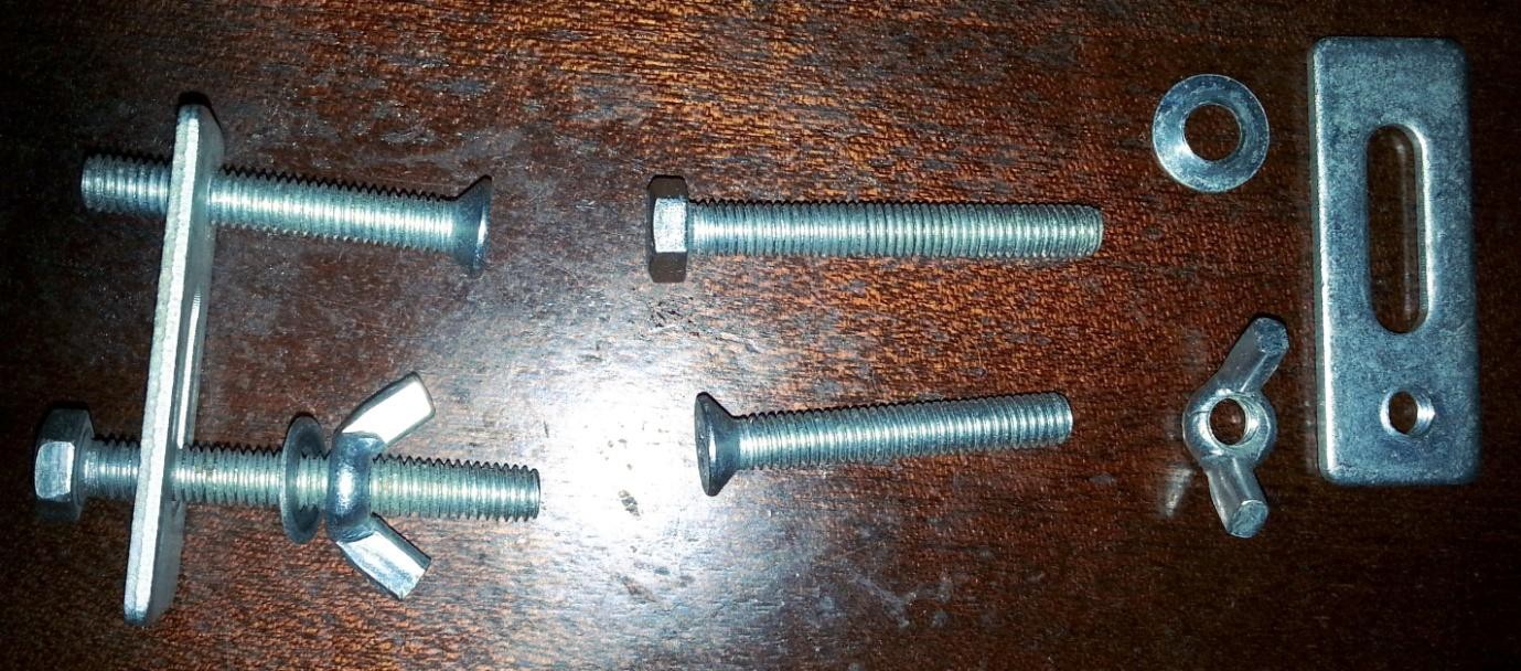
Put the pieces together so they transform into the one on the left. OK these are cheap, there are better ones out there but at extra cost, but these do the job!
The head of the bolt slides into one of the slots on the bed, the screw is used to move the plate to be approximately horizontal when the end of the screw is on the bed and the top of the plate is on the stock. The wing nut then tightens each plate onto the stock holding it firmly in place, the bolt will spin in the slot until it is reasonable tight so hold the top of the bolt while initially tightening the wingnut. Yes this is another of those ‘using your third hand’ jobs! It is best to use all 4 spaced around the stock, just one or perhaps two, will allow it to move, it depends on the depth of cut, bit you are
using on how much force is exerted on the stock. If the stock moves during the job it is [Insert
expletive here].
While clamping it down you need to make sure that the alignment of the stock on the bed is correct. Tricky to get it perfect at this stage as almost certainly your bed will be slightly out of alignment, not a lot but a little, as you are unlikely to be mounting and framing this first attempt it is close enough to use the edges and slots in the bed to be very close. Assuming that the scrap piece you are using is exactly rectangular of course!
There are other methods for holding down the stock, some of the common ones are;
- Double sided tape
- ‘Blue’ painters tape and superglue
- Gravity and friction (only applicable if you are using a laser)
- ……
Mounting the bit
Normally you will have a set of bits provided with the machine. I believe SainSmart now includes an assortment of bits with their machines, but it used to be a number of identical engraving bits.
For this first cut I suggest you use an engraving bit.
The ER11 collet (not the holder) is 18mm deep. That is the clamping length, the bit will go into the collet much further if it is long enough, but only 18mm applies any clamping force which is fine. If the bit I am using is in total 38mm long, tip to toe, it will leave 20mm sticking out of the bottom of the collet when fully clamped. You don’t want to leave too much sticking out as this will create a greater leverage from the end of the bit which can lead to it flexing or breaking (especially true for small diameter bits) and putting greater strain on the router. But you also don’t want to leave too little sticking out, it needs to be able to reach the bottom of a cut without bouncing off the limit at the bottom of the Z axis, and be capable of cutting down far enough for whatever you are doing.
Slide the bit into the collet and use the two spanners provided to tighten it up.
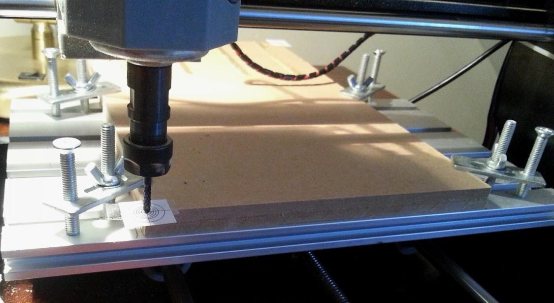
Positioning the bit
I mean moving it to the starting position on the X, Y and Z axes and telling the router ‘Start from here’. The router has to know where you want it to start before you start it, otherwise it will just assume things and almost certainly get it wrong!
Part of getting the start position right is being aware of the size of the job you are going to start and where the .nc file expects to start from. The visualisation in candle and similar software when you load the .nc file can be very useful to work this out.
So make sure the end of the bit is clear of the top of the stock and move it using the jog controls to where you want it to start. Keeping the end of the bit close but not touching the stock makes this easier to see. Fairly easy when using a V or engraving bit as it has a pointy end which you should be able to see quite clearly, not quite so easy when you use a larger flat bit or if your stock does not have clearly defined corners as you can’t see the centre of the bit or the corner of the stock.
So I have devised the Bit Positioning aid to assist. (See accompanying files)
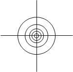
Simple in concept, it’s just a series of circles where the diameters have been chosen to match my selection of bits and any I may acquire in the future (13, 8, 5, 3.2, 1.5mm) with 2 lines across them. It’s not the sizes that are that important, it’s just by rotating a larger bit I find it easier to align it to, or in the centre of, a circle. These are a compromise, make your own, scale it, it doesn’t matter.
To place on a corner apply a bit of glue or cheap double sided tape, I say cheap as I only want it to stick for long enough to align the bit and not leave any glue residue on the stock.
To position on an edge align the cross lines up with the edges of the stock and stick it down. It is often easier to use a ruler or straight edge on the sides of the stock to assist.
These can also be used where the edge of the stock has been rounded using the same technique, if so and the centre is not supported by the stock don’t use it to set the Z axis position!
To position anywhere else, well…..
Remember you can turn the bit by hand during the alignment process to make it easier to see.
Print them out, cut them up and see if they work for you. They can be attached anywhere on your stock and removed as you see fit. Depending on what you are doing these may be totally useless! It depends on how accurate you need to be with your setup, if you are going to cut off the edges of the stock anyway then there is no need to be other than close. But if you are going to turn the stock over and machine the other side as well, this MAY make it more accurate and easier, It’s never going to be 100% accurate!
So now the bit is aligned in the X and Y axes.
Now the Z axis, Candle allows, nay requires, that the zero position of the X and Y axes and the Z axis are set separately. Not that silly as it allows you flexibility. You don’t have to set the Z position in the same place as the XY.
Setting the exact position of the Z axis zero is just as tricky as setting the XY axes position! But different. Start with the end of the bit close to the stock by eye then slowly jog the spindle down (0.1mm at a time or less) while turning the bit by hand until you encounter resistance from it touching. The problem with this is that it can mark the stock and if you are using a small bit, especially an engraving bit with a sharp pointy end it can be difficult to detect the resistance.
So place a piece of thin, Paper is excellent, material between the stock and the bit, this stops any scratching and by trying to move the material sideways you can tell when you encounter resistance to movement that it is starting to touch. Then remove the material and jog down by the thickness of the material before you set the Z Axis zero.
HINT: Make a stack of the paper until you can accurately measure the thickness of the stack, then divide by the number of sheets in the stack to get the thickness of each sheet, the thicker the stack the more accurate your results will be, it’s more reliable to measure the thickness of a large number of sheets (without a micrometer) and divide it down than it is to measure 1 by itself!
I normally use one of my printed bit positioning aids, with the card I have printed them on I know the thickness is very near to 0.25mm (I measured a stack of 20 at about 5mm).
Pressing the Buttons
So Jog to the XY axes origin, in Candle click the Zero XY button in the Control section.
Now position the end of the bit to just touch the stock and click the Zero Z button in the Control section. The Work Coordinate System origin is now fully set.
I recommend at this point using the jog buttons to retract the end of the bit to a safe distance (a few mm) from the top of the stock. This hopefully prevents the GCode file from dragging the bit across the top of the stock as it goes to the first cutting position. Not all GCode files will do this, some will, it all depends on the software used to generate it and the options used.
Fit the bit, a 20 degree engraving bit
Load your sample file in Candle. SainSmart provides these on the mini CD which came with your router. If you can’t read the CD then you can download everything from
http://wiki.SainSmart.com/index.php/101-60-280PRO A good start is 1SainSmart.nc, this is designed to use a 20 degree engraving bit.
dragon.nc is also good but takes a while to complete, just because it is a complex engraving, also uses a 20 degree V bit. In fact it is a good initial ‘stress’ test for your router, and it’s pretty!
Look at the visualisation in Candle carefully, especially the dimensions and where the origin is, make sure this matches the size, position and alignment of your stock.
Make sure Candle and the router are connected.
Click Send.
NOTE: It is possible that there may be some errors reported, even some of the (earlier?) SainSmart sample files generate errors. The most common one is an unrecognised command (error:1) Normally the error 1 can be safely ignored, it commonly consists of including a % or Txxx command in the GCode – % is an old start of program and do not rewind the paper tape when finished command. T commands mean change the tool. As the router does not have a paper tape reader or a tool carousel it does not recognise these commands.
Hopefully Congratulations, it works!
If not review and repeat!
NOTE: I forgot to say have a vacuum cleaner ready to clean up the debris!
Some background and terms – (In no particular order)
Skip this if you want, it is not necessary but if you ask for help on forums you may see these terms and concepts used and if you don’t know them then it may be useful.
Units
Pretty obvious but can cause a load of problems. Basically these will be in inches or mm, there are other variations for speeds such as mm/sec and mm/min . The software you will use to create things will have its own settings, some even will work in Inches! It is imperative that the units match, if you tell your software to work in Inches and the router works in mm you are going to get very compressed results and vice versa, move left 1 is very different in mm and inches!
Controller or Motherboard
This is the bit of electronics which controls the movement of the bit or laser and the rotation speed or laser power. On my 3018-PRO this was the Camtool 3.3 board and is now the Woodpecker CamxTool 3.4, whose brain is an Arduino microprocessor. It’s not a very big brain but works well. The Arduino microprocessor system is often used by hobbyists and for microcontrollers in situations like this. Lots of other makes, versions and types are available.
The motherboard also has all the electronics needed to drive the stepper motors which control the axis movement, to drive the spindle motor at differing speeds and the laser at different power settings, translate GCode commands received via USB or an offline controller into specific motions of the laser or spindle and receive and process other commands, for example for jogging (moving) the spindle around, changing settings, returning status etc.
Grbl
This is the software which runs on the motherboard; it basically takes GCode and translates it into the movements and speeds needed to for example cut a line. Grbl is free to use open source software.
When Simen Svale Skogsrud first sat down and wrote Grbl in 2009, he named it after a bigger version of a computer mouse. It’s small, useful, and doesn’t do much other than what it’s designed to do. So, if you ask him, it’s pronounced like “gerbil”.
Mach3
If you have the MX3 or similar models these run the Mach3 software. I have never used it.
Stepper Motor
A motor that is told to turn in small steps like turn clockwise 1.8˚ as opposed to a ‘normal’ motor that will try and continue to rotate as long as power is supplied.
All of these routers use stepper motors to control the movement of the axes; each step of the motor will turn the threaded rod a bit, which will move the things connected to it by a small amount. The amount the axes move depends on the stepper motor, the pitch of the threaded rod, the motor controller and the router motherboard.
Microsteps
Where the stepper motor is told to turn by a fraction of its rated step by application of fractional electromagnetic forces (OK Magic!). This depends on the motor and the motor driver chip used on the motherboard, one microstep determines the minimum movement or precision of the axes, this also depends on the pitch of the threaded screws.
Missed Steps
You may often see this as a possible cause of errors, quite simply it’s when the stepper motor is told to move, but for whatever reason doesn’t. The causes can be varied, asking it to do too much is the simplest, this can be because the bit is cutting deep and has now been told to move sideways putting too large a load on the stepper motor, or the machine is at the edge of its limits and that step will bang it into them, or bad wiring, or…..
But the motherboard is calculating the position of the spindle based on what it has told the stepper motors to do, it doesn’t know if they have actually done them. If the motor doesn’t move the spindle then that position is now in error. Missed steps will always cause the router to become misaligned. They can often be identified by misaligned cutting or by nasty grinding noises coming out of the router.
PWM (Or TTL)
Pulse Width Modulation, which is often implemented by Transistor to Transistor Logic (TTL). You may see either on any control board connector, but practically they are the same.
Simply put its turning something on and off very rapidly (up to 1,000 times per second). Imagine you didn’t have a dimmer switch on a light but wanted it to operate at ½ brightness. Simple, stand by the switch and repeatedly turn it on and off where it is on for 50% of the time and off for 50% of the time. OK not recommended, it will probably give you a headache, but if you use a computer or electronics to do this 1,000 times a second all you will see is the light burning at 50% brightness.
Change it so it is on 75% of the time and it will be brighter, less and it will be dimmer.
Spindle Motor
This is the ‘big’ ‘normal’ electric motor which holds the cutting bit. The power it is supplied can be varied changing the speed of rotation, the rotation speed also depends on the amount of work it is being asked to do, just like driving a car at a steady speed on the flat, starting to go up a hill the car will start to slow down as the engine is having to do more work.
The motherboard uses PWM to vary the speed but provides no feedback to measure the speed. So it’s more of a power setting. Normally it is set as a maximum speed of 1000 even though the RPM of the standard Spindle motor will be higher, the best I can find for the true speed is about 8,500RPM under no load at the 24V supplied by the router motherboard.
This value is not going to be linear, in other words a speed of 500 will not be exactly half the RPM of a speed of 1000.
Bed
Not for sleeping, this is the flat aluminium bit which holds the stock with slots in it to allow clamps to hold the stock down.
Tool Holder
Simply this is the piece that fits onto the end of the spindle and holds the bit, the chuck on a drill.
ER11 Tool holder
The commonest tool holder on this type of machine, it is manual requiring a couple of spanners to release and fasten it by tightening or releasing the collet which clamps the tool.
Collet
The piece inside the tool holder which as it is tightened into a tapered hole contracts around the bit so holding it.
This only tightens so far, a collet has a limited range of movement around the bit, but the diameter of the hole in the centre determines the range of bit sizes it can clamp. The standard collet supplied with mine can take a bit with a shank of around 3.175mm (or 1/8”). Other collets are available! I have the SainSmart collet set which allows me to use bits with a shank diameter of 1 to 7mm NOTE: a bit with a ¼” shank diameter fits into the 6mm collet.
HINT: If you need to change the collet unscrew the end cap from the end of the tool holder, this will leave you with the collet inside the end cap, it snaps in. Now push the end of the collet as far as you can over to the side of the end cap tilting it. Using your third hand press something flat like the end of a spanner onto the collet to break the snap in effect and push it out.
Bit (or Tool) Introduction
The sharp, sometimes flat, often pointy thing which rotates and cuts bits out of the stock.
So many to choose from, so you know what you are buying. Remember this is a bottom end machine, larger routers with much higher powered motors can happily drive the larger bits and will routinely do so, however at this level if you try and use a 50mm diameter bit then these routers
probably won’t be able to turn it when it starts to cut, certainly not at the speeds it was designed for. See a later section on bits.
Stock
Whatever you are trying to engrave, cut or carve.
Tabs
Not credit in a bar!
If you for example are cutting out a shape then when you get towards the end of the cut there is nothing holding in the centre. Fine if you have fixed it down, if not then it will start to move as the last bit of material is removed. This is commonly known as a disaster! It will collide with the edge of the stock cutout and the bit damaging the edges and if it wedges in the wrong place potentially breaking the bit!
Tabs are where you set in the model a number of small bits of material which should NOT be cut out to hold a centre piece in position, It’s like a coarse perforation round the edges of stamps! These have to be removed manually when the cut is finished.
Tiling
A technique for making things larger than your router. The gantry of the router effectively limits the width of the stock to 300mm, however there is nothing to stop it from sticking out of the front and back, but you are only going to be able to cut or engrave a maximum of 180mm at a time. But after doing the first bit you can move the stock up or down and cut or engrave the next 180mm. The problem is being able to align the 2 or more ‘tiles’ exactly.
Spoilboard/ Baseboard / Wasteboard
A bit of sacrificial material mounted on top of the bed and underneath the stock which can be levelled exactly. Baseboard, Wasteboard and Spoilboard are just synonyms. Here I will use Spoilboard.
Why use one, there are a number of reasons.
If you are trying to cut completely through the stock creating a stencil with the laser or cutting out a piece from the stock without a Spoilboard of some sort you are going to start cutting the nice shiny Aluminium Bed. And if for example you are using a router bit to cut through wood it is suddenly going to make contact with a piece of Aluminium which is a lot harder and it probably won’t like it. It will get blunted and possibly break to say nothing of what it will do to the bed!
It is important that the bit (or laser movement) is absolutely parallel to the surface of the stock. Imagine if the right hand side was 1mm lower than the left. If engraving for example this would probably mean that if you started on the left by the time you got to the right the bit may not even be touching the surface. If routing or carving your cuts may be too deep or shallow.
Using a Spoilboard mounted permanently and securely means you can use a bit to slightly level or face the surface which makes the top level with the movement of the bit. Even if the level of the bed is slightly out which it almost certainly will be, after facing it the top of the Spoilboard will not be, as long as it is securely mounted and is not moved. If the level of the bed is out by 0.2mm on the X axis this gives an angle of roughly 0.03 degrees so put away the spirit level!
As a last step I engrave my Spoilboard with a grid. These lines are exactly parallel with the actual movement of the bit or laser which makes aligning the stock to the actual movement, even if the bed itself is a little skewed which it will be, much easier.
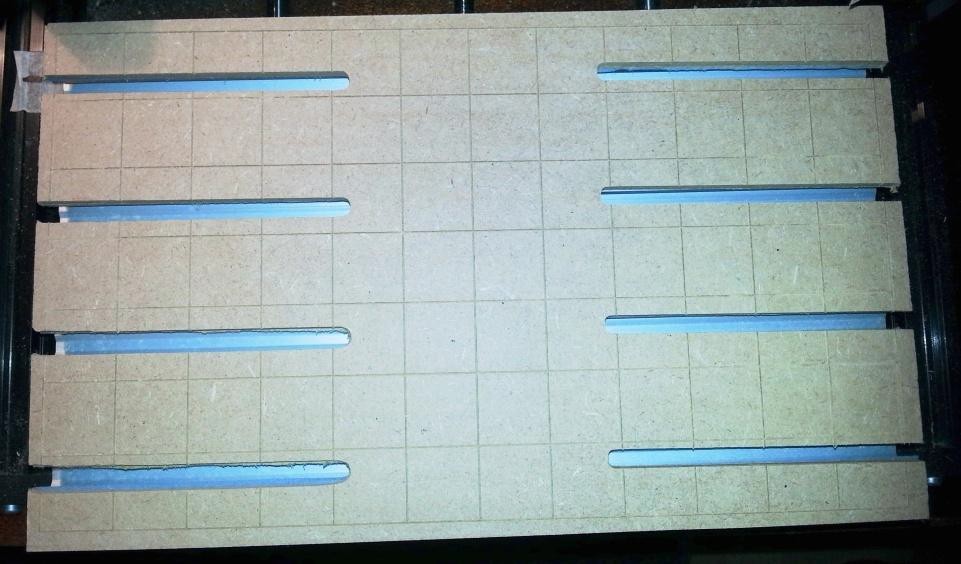
It’s a new machine with a clean and shiny aluminium bed, so let’s keep it that way. It’s really all that simple. (Coughing fit!)
Lots of room for experimentation here!!!. See “Introduction to CNC for a Total Novice – Making a Spoilboard.”
GCode
Geometric Code (I think) is a set of simple and some more complex commands which basically work out to go to there, up a bit, down a bit, left a bit, spin faster…….
The router motherboard reads these commands one by one and translates them into the commands sent to the stepper motors driving the axes and the spindle motor or laser. So to get the router to do anything it needs a series of GCode commands, as that is what it understands, it uses those commands to control the movement of the bit in all the axes at the appropriate speed.
GCode is normally saved with a .nc file extension, although other file extensions are used, it’s just a text file which can be opened in any text editor or viewer. So if your CAM software generates XXX.GCode and your GCode sender only reads .nc files just rename it. Some software will connect directly to the router and just send it the commands rather than saving a GCode file and letting something else send it to the router.
GCode dates back to the 1950’s and to be quite honest it is not a standard, well there are lots of standards. In the words of Barbossa The code is more what you’d call “guidelines” than actual rules. Welcome aboard the Black Pearl, Miss Turner!
Every CNC manufacturer ignores bits which they don’t implement, like the tool commands which say go and pick up tool x from the automatic tool carousel, the 3018 doesn’t have a tool carousel so it generates an unknown command error on a Tool change command even though the GCode is valid. Manufacturers often add extensions to support the unique features of their machines.
List of Supported G-Codes in Grbl v1.1:
– Non-Modal Commands: G4, G10L2, G10L20, G28, G30, G28.1, G30.1, G53, G92, G92.1
– Motion Modes: G0, G1, G2, G3, G38.2, G38.3, G38.4, G38.5, G80
- Feed Rate Modes: G93, G94
- Unit Modes: G20, G21
- Distance Modes: G90, G91
- Arc IJK Distance Modes: G91.1
- Plane Select Modes: G17, G18, G19
- Tool Length Offset Modes: G43.1, G49
- Cutter Compensation Modes: G40
- Coordinate System Modes: G54, G55, G56, G57, G58, G59
- Control Modes: G61
- Program Flow: M0, M1, M2, M30*
- Coolant Control: M7*, M8, M9
- Spindle Control: M3, M4, M5
- Valid Non-Command Words: F, I, J, K, L, N, P, R, S, T, X, Y, Z
If it’s not in the list above (taken from the Grbl 1.1 release notes) it will be unrecognised and an error will be returned from the router, these invalid command errors (error:1) can normally be safely ignored.
GCode can even be generated by hand as it was in its early days. For example S100
M3 G91
G1 Z-0.1 G1 X10 Y10 G1 Z0.1 M5
Means Set the Spindle speed to 100RPM, Turn the spindle motor on in a clockwise direction (Or laser On), Use relative positioning – each movement specifies an offset from the LAST position, Move the bit 0.1mm towards the bed, Move the bit 10mm to the right and 10mm up as a linear move, move the bit away from the bed by 0.1mm, turn the spindle off.
But as nowadays we have these newfangled things called ‘Computers’ for anything other than the simplest of jobs, coding this by hand this would be exceedingly tedious, there is a reason computers were invented.
So practically to generate anything much more complex in a GCode file we need software. But that unfortunately creates its own set of problems. Commercial stuff is built for precision and speed and as GCode isn’t really a standard but a set of them manufacturers are relatively free to add features, interpret things in slightly different ways. So the CAD/CAM software has to generate the GCode
specifically with each specific machine in mind. Even in the hobby world there are differences, the easiest one is does your router have limit switches which allows it to set a machine position, is it mounting a spindle motor and bit or a laser, and how powerful is it?
There are lots of GCode tutorials out there so I am not going to even attempt to duplicate them, but beware of how machine specific they are, although the general principles will be the same.
I have found however that it is useful to have at least a basic understanding especially of positioning and coordinate systems to try and work out what has gone wrong. Don’t blame the router it’s a fairly dumb machine which tries to do exactly what it is told!
Toolpath
Simples, the path that the tool is moved along in order to do the job. This is normally expressed by the software analysing the model, using the information you have told it about the tool, how fast to move it etc and generating a GCode file which tells the router what to do in little pieces. Up a bit,
down a bit, left a bit Often your software will provide a toolpath simulation so you can see on
your computer what is going to happen before you send it to the router.
WARNING: These simulations always seem to ignore the getting the bit to the start of the cutting and returning it somewhere at the end. That’s because they don’t know where your bit or laser is going to be when you start the job.
Limit Switches or End Stops
Switches which trigger at the limits of movement for each axis. Used to allow the router to establish a ‘Home’ position by moving around until they are triggered. In operation they will stop the router from trying to move past its physical limits by generating an alarm. Not fitted to the 3018-PRO.
Soft Limits
This can only be used when a home position can be set via a homing cycle. It allows you to use 3 limit switches to detect the left, front and top limits, all that is needed to set a home position, rather than fitting 6 to also determine right, back and down limits.
Soft limits set the maximum travel from the home position, the router software checks if a movement will exceed the machine limits and raise an alarm if it will, just as it would if a limit switch was activated.
Coordinate systems
When you turn on your router it has no idea where it is on any of the axes, it doesn’t save its position and even if it did you could have manually changed them. All it knows is ‘I am here!’ Pretty much like me waking up in the mornings.
One thing to remember, these are hobby machines, the main drive, at least until recently, for the development of CNC is commercial manufacturing. If you are expecting to spend £250 on a router you cannot really expect the same construction, tolerances and features you would get if you were spending £25,000 on the machine.
You need to know three things and how they relate to each other to stop your machine scraping the bit over the top of your stock, suddenly deciding to plunge down as far as it can or banging against the physical limits of the machine:
- Home or Machine coordinates
- Safe Position
- Work Coordinate System
Home/Machine coordinates
The Home position is where the spindle is when you turn it on! This position is remembered as the home or machine origin position, not a lot of use, but higher end machines have these devices called limit switches which tell it when it has reached the limits of travel. This allows the use of a homing
cycle where it moves to test when the switches activate so telling it where a ‘Home’ position is. This is normally the spindle being at the bottom left corner and as high up as it can go.
This position cannot be set via commands to the router other than telling it to perform a homing cycle. Well it can, but only by jogging somewhere close to it and then powering the router off and on or resetting it, it sets its power on position as home.
Safe Position
I always had a safe place where the monsters were unable to reach me. Well routers are the same, have you stroked yours lately and told it that at least you like it??
Often Software will generate GCode using the G28 series of commands which specifies a ‘safe’ position to which it should return to. This is RELATIVE to the home position and it is remembered by the router. By default , unless the router receives a G28.1 command, which is set the safe position, it will be an offset of 0 on all axes from the Home position, so if you don’t have a consistent ‘home’ position it can rapidly become an ‘unsafe’ position!!!
Going 20mm up, 90mm right and 5mm forwards when you don’t know where you started from is not a good idea!
Certainly Fusion 360 generates the GCode with moves to the ‘safe’ position on by default, but you can turn it off in the Grbl post processor options, turn G28 Safe retracts off.
Imagine the following circumstances:
- When you turn the machine on the end of the bit is 1mm above the top of the Spoilboard.
- Jog the bit out of the way.
- You mount some stock, lets say 5mm thick using clamps on the Spoilboard.
- You run a milling job.
At the start the code tries to send the bit to the home or safe retract position, normally first moving to the Z axis safe position then to the XY axes safe position in a straight line. At the end of the job the bit is returned to the home position the same way.
PROBLEM! The clamps and what remains of the stock are probably in the way, this can be disastrous as it tries to smash its way through things. Sometimes you will see people reporting that at the end, sometimes the start, of a job that the bit is dragged across or through the surface marring the stock or starts by plunging straight down. This is the probable reason why.
Work Coordinate System (WCS)
Sometimes referred to as Local Coordinates. This is what you will be using for every job!
Most machines including GRBL ones support multiple origins. This is so if you want to make multiple parts at the same time you can set up multiple origins then say use Origin 1 – Make the part, use Origin2 – Make the part Apart from letting you know about it I am now going to ignore it.
This is basically setting a position for the start of the work, or work origin. Even if your machine knows its home position it’s still going to base an operation on WCS as it’s easier to position the bit
or laser to the bottom left, touching the surface of the stock than it is to mount the stock exactly according to the home position.
In other words jog the bit or laser to where you want to start the work, tell the router this is the WCS zero position and go from there.
It is your responsibility to make sure that you are not going to tell it to go outside its physical limits.
It is also your responsibility to make sure that the router can get to the start position without damaging anything, for example don’t leave the bit below or exactly on the surface of the stock! The first command sent to the router may well be to go to the WCS Origin or wherever the toolpath starts. This will be in a straight line so if there is something in the way?
CAUTION: Your Software will normally allow you to set a home position on your work before generating the GCode, Fusion360 is an example of this, you can set the origin of the work coordinates to bottom left, top right or anywhere else you chose normally relative to the stock. Top Bottom Left seems to be the most common but beware! If they don’t match the physical environment, stock position, starting position etc. of your router then there will be problems ahead.
Jogging to the start position is NOT enough depending on the software you are using, you must also register this as the starting position. Or your router may first go to where it thinks the start position is before starting. Within the Work Coordinate System (WCS) there will be a few buttons you can press on your PC. One will be to set the current position as the origin, In Candle this is the Zero XY and Zero Z buttons, in LaserGRBL this is the globe along the bottom of the screen.
It reminds me of a very old joke where a stranger is asking for directions, one guy looks and says that is difficult, if I was going there I wouldn’t set out from here, I would go to the next village first!
Examples
Firstly why am I spending so much time on this? Well it’s important and took me quite a while to fully (used in its loosest sense, sort of may be closer) understand what was going on.
NOTE: These are simplistic, just designed for illustration; real life is a lot more complex!
Take the following:
- Turn the machine on with the bit in the top front left corner, this becomes the home position. Or more likely turn it on, jog the bit to the top front left corner and then reset it.
- Mount the stock.
- Move the bit to the WCS origin using Jogging commands.
- Set the XY and Z axes WCS zero point.
- Jog the bit a little out of the way (optional).
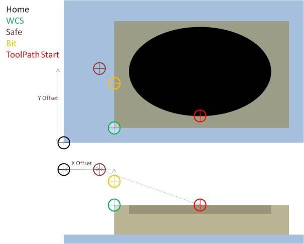
Now when you send a job to cut out the stock often the program generating the GCode will first move the bit to the Safe position normally Z axis first, often only the Z axis because that is safe. Then go to the start of the toolpath to start cutting. Everything fine!
But what if?
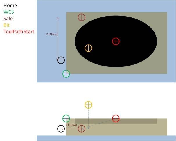
When you turned the machine on the end of the bit was close to the bed
OOPS! Going to the safe position is not safe, remember it is based on where the spindle was when you turned the router on, it’s actually in the middle of the stock! So expect the bit to try and plunge down into the stock before going to the toolpath starting point for the cut almost certainly in a straight line. After the job if it tries to return to the safe ‘Home’ position, then another Oops!
Even if it just says go to the start of the toolpath depending on where the bit is that may not be safe, if it was left at WCS origin then it will scrape its way across the stock to get there!
Here is the start of some GCode to cut a pocket generated from Fusion 360
| GCode | Description |
| (1001) | Comment, Program Name |
| (T1 D=3.175 CR=0 – | Comment, Tool details |
| ZMIN=-2 – flat end mill) | |
| G90 G94 | Use Absolute positioning, Set federate units as X/mm/minute |
| G17 | Set the plane as X/Y |
| G21 | Set Length units in mm |
| G28 G91 Z0 | Rapidly go to the relative(G91) position of the Z axis as saved in the router. G91 mode is NOT saved. If G28 safe retracts is set to ‘No’ this line is omitted but everything else stays the same. |
| (2D Pocket1) | Comment, start of operation |
| S1000 M3 | Spindle speed 1000 and turn it on rotating clockwise. |
| G54 | Select Work Coordinate System 1 |
| G0 X94.583 Y58.394 | Rapid move to the X and Y coordinates from WCS Origin |
| Z10 | Move Z axis to 10mm above WCS origin |
| Z5 | Move Z axis to 5mm above WCS origin |
| G1 Z2.817 F500 | Cut down 2.817mm from WCS Z origin setting a feedrate of 500mm/min. |
Absolute vs Relative Coordinates
The router will use either relative (G91) or absolute (G90) coordinates depending on the last one of these instructions it received. Relative means go 5mm to the right of where it is now, absolute means go 5mm right from the Home position or Work coordinate system origin depending on the command and current modes.
Jogging
Don’t worry, in CNC terms this can be performed while sitting down and does not involve any physical activity other than moving a finger, maybe a hand as well!
This is a term used for manually moving the spindle around using buttons on the computer. These move the spindle around by varying, settable, amounts and are normally used to move to the Origin needed to start a job, or to move the bed to the front and the spindle out of the way to give easier access to set up a job.
NOTE: If using jogging to move to the origin of a WCS then putting it in place is not enough, you will also have to specifically tell the router that this is where you want to start from by zeroing all the axes.
Stock
The stock is the term for whatever you are cutting, engraving, milling, whatever.
Different materials have different characteristics. You need to understand and experiment, which I am looking forward to.
This router is, “Capable of cutting all types of plastics, soft aluminium, woods, acrylics, PVCs, and PCBs, the Genmitsu can be used on a wide range of projects and materials.”
But there are large differences in the details, the harder the material the more difficult it is to cut!
Feed
The rate/speed which the bit or laser is moved through or over the stock (Fxxx); this is controlled by the axes stepper motors. This is normally expressed as mm/min, and that is what the 3018-PRO uses by default for feed rates.
There are many other ways of measuring the feed rate, some depend on the bit you are using to try and calculate how much each cutting edge is cutting out of the stock. This is normally best left to the professionals for the moment.
Speed
The speed of rotation of the spindle(Sxxx), for a laser the power it operates at. Remember the 3018- PRO has no measurement of the actual spindle speed or power, so mostly this works out to be faster and slower. As such if you try and do too much the spindle will slow down… In a much more expensive machine a spindle speed of 500 would probably mean 500 RPM.
Simple, but….
Feed and Speed are somewhat dependant on each other, the goal is to achieve the cleanest possible cut hopefully in the fastest possible time with no wear on the tool, although as a hobbyist the time can be less important than to a professional.
Also to be taken into account is the stock material and the depth of cut you are trying to make.
Think of it as the amount of material you are trying to remove in one go. The faster you set the feed the more the cutter will travel on each revolution making for a thicker cut, the faster the spindle speed the amount each rotation of the bit has to remove is lower.
Passes
This is basically the number of times you tell the router to retrace the same path, probably with a bit of go down between each pass.
If you want to cut a groove or pocket in a piece of wood 5mm deep you are not going to do it in one single, go down 5mm then cut! If the wood is very soft and the bit is very sharp, maybe, but you take the risk of overloading the router, wearing out or breaking the bit by trying to make it do too much work in one go.
You can get round this by telling your CAM software to make multiple passes cutting out a little each time. As a general rule the less material you take out the better the finish quality but the longer it takes.
This also depends on the hardness of the material, you would need more passes using smaller cuts on oak than you would on a soft pine. Take notes so next time you have a better idea where to start!
Z-Probe
NOTE: Before discussing Probing or Z-Probes in public make sure that the people within listening distance are all into CNC Routing. Otherwise they will either think you are an Alien in disguise or have just been returned after your abduction.
A Z-Probe is a simple device, it’s a piece of conductive material with a wire attached (Or a spring loaded switch). Another wire is connected to the router and clipped to the bit in the spindle motor. (it’s a switch) Very simplistically the bit is lowered onto the stock until contact is made. This tells the router where the origin of the Z axis should be.
I haven’t got one!
Lots of different ideas and suggestions on the Internet and forums.
Height Map
This (if your software supports it) is using a Z-Probe repeatedly over the stock to build up a map of the heights. Often used when engraving Printed Circuit Boards where the vertical tolerances required to engrave the PCB correctly are very fine. When engraving the software uses the map to adjust the Z axis to correct the actual height of the bit relative to the stock depending on the XY position.
Vref
The router motherboard contains motor drivers for each of the stepper motors. Depending on the stepper motors you have the maximum amount of current each driver can supply is controlled by a Voltage reference or Vref which is set by turning a small trimmer pot on each motor driver. This can be adjusted by turning the trimmer pot using a very small screwdriver and measuring the voltage from the pot to ground. The exact setting depends on the stepper motor and the motor driver chip. Too high and the driver will try and provide too much current and probably burn out. Too low and the stepper motor won’t get enough current and could miss steps. If your supplier has good customer support it is likely that they have taken some care to get this right as to be honest it costs money to replace motherboards. If not it could be worthwhile checking, also if you replace the motherboard which may not be set up for your exact machine.
Search the Facebook SainSmart Genmitsu CNC Users Group for vref, my thanks to Steve Harhai.
Offline Controller
This is a small module with an SD card which connects directly to the router Motherboard. It can read a GCode file from the SD card and send it to the router. A bit limited in what it can do but very useful if your PC is too far away from the router or you don’t want to tie it up for the duration of a longer job. NOTE: You cannot connect the offline controller and a USB to the router at the same time! They use the same serial interface on the router and it will get very confused! Also the offline controller has a USB interface which allows it’s SD card to be used by the PC as a drive. Don’t use this while the Offline Controller is talking to the router!
The Process
Before you start doing anything it helps to understand the process you are using Starting at the Router and working backwards.
The router understands a set of commands called GCode. Plus some other management bits and pieces. It receives these over a serial communications link, normally from a PC or other device such as an offline controller.
Talking to the router
The bottom layer is the bit you need to send the GCode to the router. At the end of the day ‘all’ you need is something that will send a text (GCode) file to the router.
However some clever people have taken this and added some useful bells and whistles. The 3018- PRO uses the Grbl program on its motherboard. So if on your PC you use Candle/Grbl they will talk to each other quite happily (as will others). Candle also adds some other useful features such as allowing you to move the router bit around, set zero position, see what is happening etc…..
If you are using the laser module LaserGrbl does much the same but is more set up for using a laser.
There are also things like Offline controllers which can read the .nc file off an SD card and send it to the router without it having to be connected to your PC.
There are lots of other possibilities but for the 3018-PRO you will be using Grbl based systems.
CAM (Computer Aided Manufacturing) Process
Basically this takes a model, be it a picture, 2D or 3D model and determines how the tool needs to be moved in order to create the GCode necessary for the router to carve or engrave the part out of the stock material. This is called generating the toolpath which is then converted to GCode.
In order to do this it needs to be told things like what tool it is using. This can make a big difference if you are using someone else’s GCode file! If they built the GCode to use a 20˚ engraving bit and you are using a 3mm routing bit or vice versa the results are not going to be good! Also you are not going to be able to carve or drill a 2.5mm hole using a 3mm bit. And if you are trying to carve aluminium rather than soft pine you will certainly need to tell the router to use a slower feed rate to move the bit and a different spindle speed…..
The CAM software will almost certainly allow you to specify things like the number of passes to make, how much the bit should be lowered between each pass etc…….
CAD (Computer Aided Design) Process
This is defining what you want without having to, at this stage to specify how to make it. This could be a 2D graphics processor (engraving Jpegs) up to a full 3D modelling system. The output of this is fed into the CAM process.
Unfortunately this does not mean you can totally ignore the manufacturing process even when designing things, you are not going to be able to make a 90 degree internal corner when using round router bits, you will have to add a fillet (radius on a corner) size suitable for the router bits you have and intend to use.
Welcome to The Real World!
The boundaries of the process model can get very blurred by what you are trying to do and the software you are using.
For example I am learning Fusion360 as a CAD/CAM tool, not only does it provide all the CAD functionality it also has a Manufacture mode where it does all the CAM work generating the toolpath and creates the GCode file to be sent to the router.
Candle, which mainly is the talks to the router bit, can also load graphics files and generate the GCode before it sends it to the router without saving a GCode file, this is CAM as well as talking to the router.
It’s all really simple (Cough, Cough)!!!!
But regardless of the software you choose to use the process is the same, it’s just that different software developers have chosen to implement different parts of the process model.
Bits in more detail
So you have the router, a piece of wood or something and want to make something, you are going to need a bit to put at the end of the spindle.
There are lots and lots and lots of choices here, hundreds, nay thousands, nay hundreds of thousands!
Bear in mind that most of them are designed to be used on much more powerful machines and that as standard your router almost certainly comes with a collet which will take a 3.175mm (1/8”) shank.
First some terminology (NOTE: As always there are lots of names in existence for the same thing).
| Term | Description |
| Collet | The part of the tool holder that squeezes tightly on the bit to hold it in place. The size of this must match the shank size of bit you are using. |
| Shank or Shaft | The part that goes into the collet of the tool holder |
| Shank Dia | The diameter of the Shank, this must match the size of collet you are using or it either won’t fit or you won’t be able to tighten it enough to hold it in place. |
| Shank Length | The length of the shank, before it turns into a cutting surface, which can fit into the tool holder’s collet. |
| Stickout | The distance the bit sticks out from the bottom of the tool holder collet, this is used by some speed and feed calculators. |
| Flute | A cutting edge at the end of the bit. |
| Flute Length | The length the cutting surface extends up the side of the bit. This would be the maximum depth you can cut in one go. This is practically far, far more than the bit can cut at any one time. |
| Flute Count | The number of cutting edges at the bottom of the bit. A 1 flute bit will take a chunk out of the stock every rotation, 2 flutes means every ½ rotation More tends to give a finer finish, but only at a slower feed rate. (I think) |
| Overall length | Total length of the bit tip to toe. |
| Shoulder length | The length of the bit from the tip before it becomes wider than the cutting diameter. If the diameter is less than the shank diameter this is the maximum depth it can go into the stock regardless of any number of cutting passes. |
| Diameter | The diameter of the cutting tip and/or flute, the size of the hole it will make. |
The 3018-PRO has an ER-11 collet holder at the end of the spindle motor. As standard this is supplied with a 3.175mm (1/8”) collet. Upgrades are available, search for ER-11 collet, SainSmart also sell a set which covers 1mm to 7mm shank Diameters.
NOTE: Lots of bits you may see advertised are for much more powerful routers, While the 3018-PRO is not a 1 Stone weakling (well actually in CNC terms it is), neither is it Charles Atlas. The larger the diameter of the cutting surface the more power it takes to turn it and drag it through the material.
Bit Types
This is a very brief discussion of some of the various bit types and is NOT all inclusive.
| Name | Description |
| V|V Groove|Engraving | V says most of it, the cutting tip is a V shape with the sides of the V being at various angles to each other. Believe it or not this will cut a V shaped groove in the stock. |
| End Mill|Router | These are designed to cut straight groves in the stock. There are lots of variants. |
| Surfacing |Fly Cutter|Spoilboard | Surfacing bits are designed to cut a flat surface, used to do a first cut on the stock to level and smooth it out and also used to give your Spoilboard a perfectly flat and level surface. Larger diameters tend to give a flatter finish, but also take more power! |
| Ball Nose | Instead of a flat or nearly so cutting end these are rounded which gives better results on relief carvings. If you use them to clear out material from a pocket, they will leave small ridges where cuts overlap. |
| Upcut | These have the groves on the bit arranged so they pull any cutting debris (swarf) upwards, away from the bottom of the bit. Good for machining hard materials but can lift the top of the stock a little causing a ragged edge, especially for example in Plywood. |
| Downcut | These have the groves on the bit arranged so they push any cutting debris (swarf) downwards, towards the bottom of the bit. Bad for machining hard materials but can make the cut on the top of the stock cleaner, especially for example in Plywood. |
Selecting the right bit for an operation is very important! If you want to engrave some lettering, well think first of using an engraving bit, a 3mm router bit will only cut as a minimum 3mm grooves. Also you can’t cut a square groove with a V or round nose bit; it just can’t get down to the corners.
Search for help. I found useful http://www.tinkerandfutz.com/a-guide-to-cnc-bits/ But remember their router is bigger and more powerful than yours so don’t try the 2 ½ inch surfacing bit on a 3018 Pro!
Also https://youtu.be/xtqgSZlM65k is a well worth watching guide to the bits that SainSmart currently sell (at the time of writing).
Software
The big question, so far all we have covered is the router and Candle to set it up.
There is loads of it out there, what you find best is going to be very personal, depending on what you want to do and how you like the software to work. All the software has its own quirks, expected user level and capabilities. The simpler the software normally the easier it is to learn, but it can often be restricted in its capabilities, are you designing a jewellery box or a space shuttle? Depending on the answer your software choice will probably be different.
This is really a separate topic and at some time I may do a survey but that’s going to take a long time.
As a starting point Google “CNC Router Software” there is lots out there. Some that seem to be frequently used:
- Fusion 360
- Easel
- Carbide Create
- Inkscape
- Lots and lots More………
Search Google for them, watch some tutorials and take your pick!
Maintenance
Not a lot is needed but a little never hurts.
- Keep it clean(ish) especially the threaded rods and the guide rods, machining, even using a laser is a dirty business.
- The threaded rods and guide rods will need lubricating every so often to keep things running smoothly and prevent any squeaking or binding. A dry lubricant is preferred to prevent the dust from sticking to the rods.
- Every so often check all the frame, bed mounting and motor mounting bolts for tightness. Also check the tightness of the grub screws in the couplers between the stepper motors and the threaded rods.
- Visually check the bearings on all the guide rods to make sure the bearing guides are not working loose. These are a push fit and if any start to work loose at least apply a dab of glue before pushing them back in, preferably wait until a groove appears and then carefully lever
the bearing completely out, clean it, apply epoxy thinly round the grooves and then push it back in.
What to do next
Well enjoy experimenting with and using your router!!
I would suggest making a Spoilboard (See Introduction to CNC for a Total Novice – Making a Spoilboard) and if you are using a laser Introduction to CNC for a Total Novice – Setting up a laser. Other guides are available!
Acknowledgements
I would like to thank:
- All those involved (too many to list) in creating Grbl, releasing it as a free to use Open source project and supporting and improving it.
- Denvi for creating, improving and supporting Candle as a free to use Open source project.
- Arkypita for creating, improving and supporting LaserGRBL as a free to use Open source project.
- SainSmart Customer support for all their help and standing behind their product.
- All members of the SainSmart Genmitsu CNC Users Group on Facebook, both for answering my stupid questions, showing inspiring examples and asking questions that made me think.
- Steve Harhai for taking the time to review this and make suggestions to improve it.
- ………..
This is not intended as a definitive manual but it may help with some of the principles and techniques involved. If nothing else writing this down has clarified my understanding.
Any comments, proofreading, other ideas or discussions welcomed. Regards
Graham Bland.