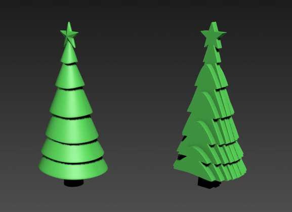
Slicing of the model for CNC machining using a sheet material
Run 3ds max
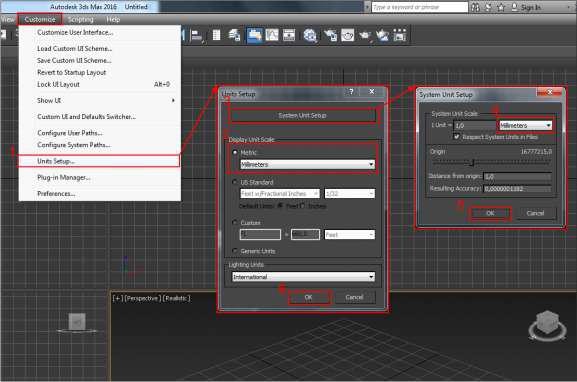
To avoid the measurement units confusion use millimeters. Go to the Customize> Units Setup in the menu. In the Display Unit Scale section of the opened Units Setup dialog box, select the Metric button and choose millimeters from the drop-down list. Click the System Unit Setup button. In the opened window select millimeters. Click Oк.
Import of the model
Click the application button and select Import.
Select the necessary file and click Open.
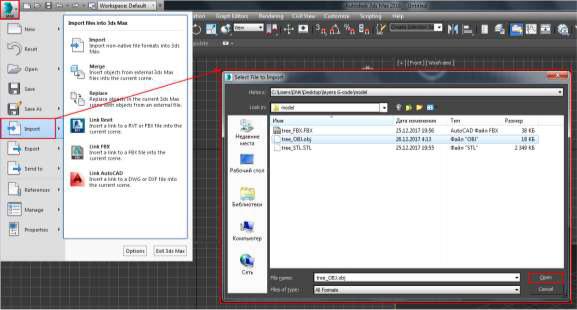
Depending on the file extension, a window with settings will appear.
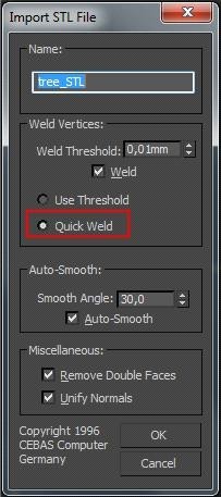
When importing from STL, in the Import STL File dialog box in the Weld Vertices section, select the Quick Weld switch. This will greatly accelerate the import.
Сheck the model for the surfaces intersection.
Select the model and make it translucent by pressing Alt + x. On the front view create a section Create> Shapes> Section
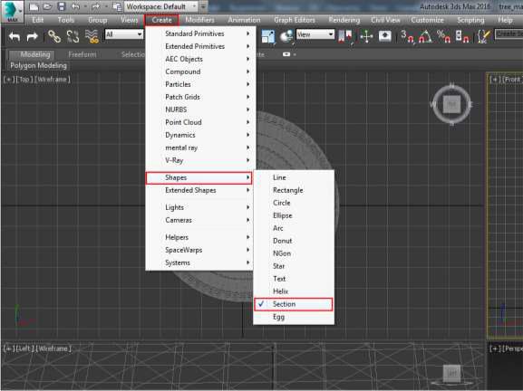
The surfaces intersections are well seen now.
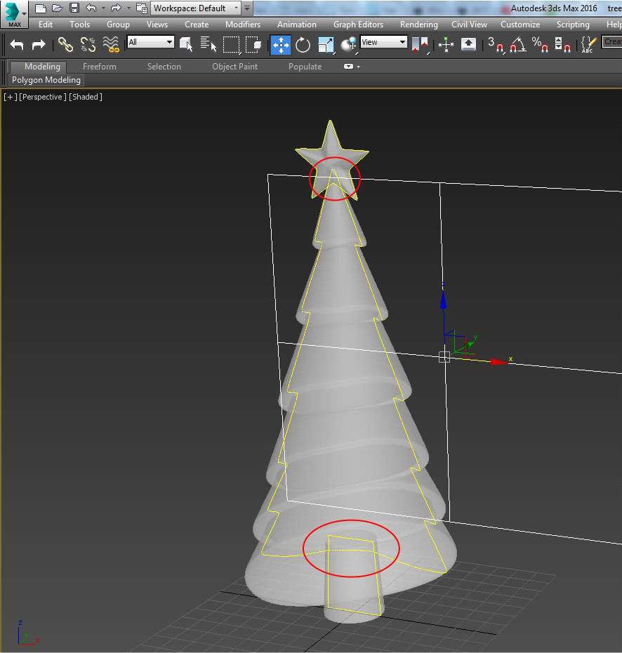
Delete the intersections.
Select the fur-tree image.
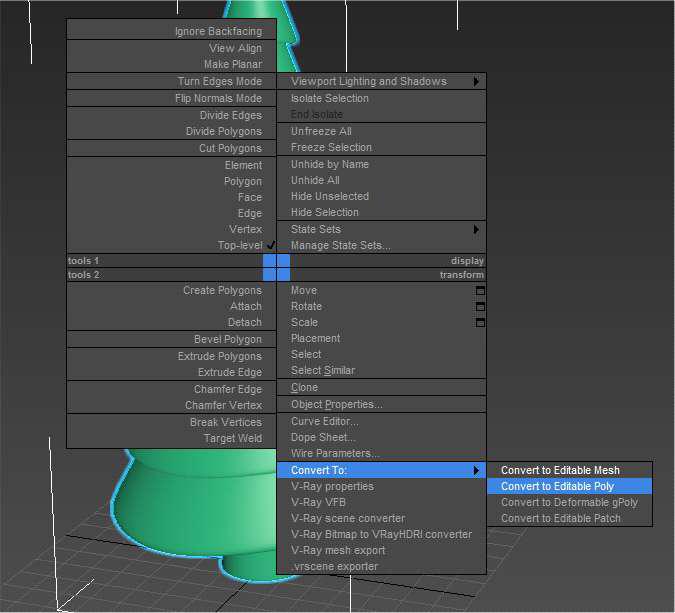
Convert the model to Editable poly by right clicking the view window (Convert to Editable Poly).
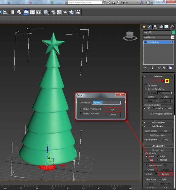
By clicking the 5 key go to the mode of the elements selecton. Select the trunk of the tree and click Detach in the Edit geometry toolbar.
Do the same with the star. Now you have three separate objects.
Combine them using the boolean operation.
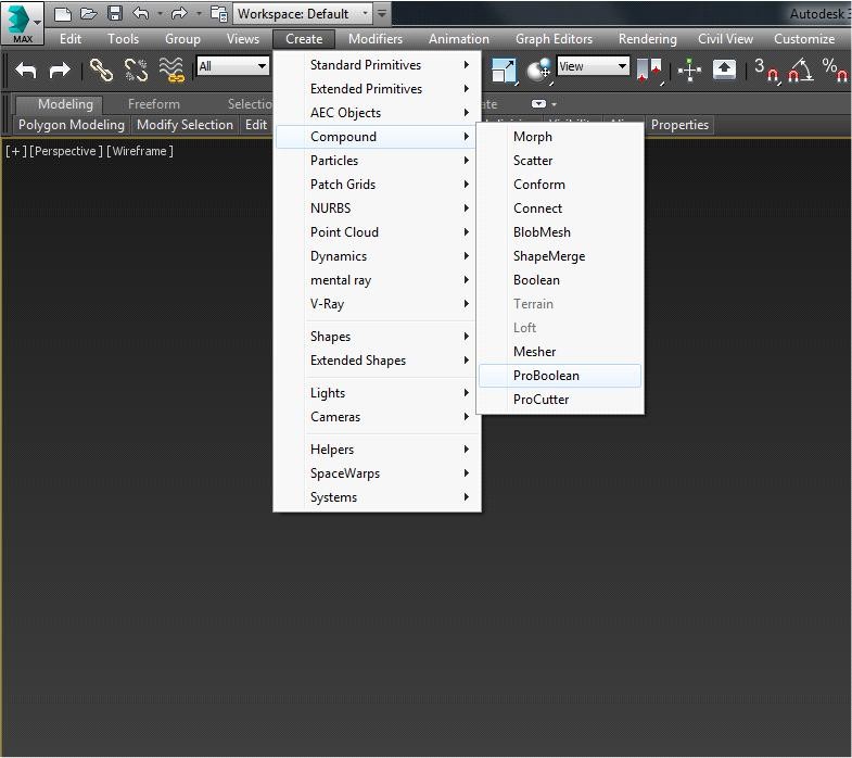
Select the fur-tree and Create> Compound> ProBoolean
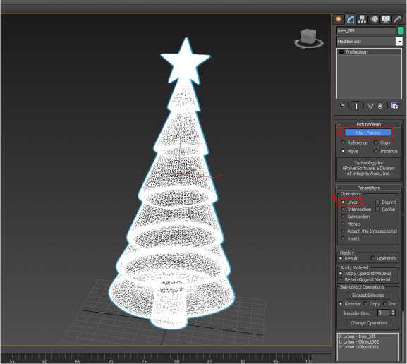
In the Parameters of the toolbar switch to Union.
Click Start Picking. Select the star. Once again click Start Picking to finish the object selection.
Now the model does not have intersecting surfaces.
Bring the model to the size you need, so that its height becomes 10 cm.
Create a box Create> Standard primitives> Box.
In the toolbar Parameters set the Hight at 100 mm
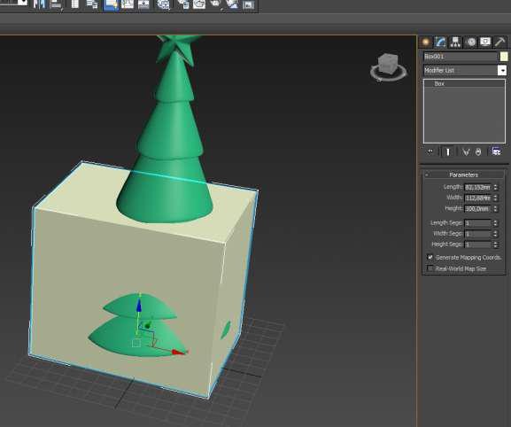
Click the R key to select the Scale tool. Adjust the size of the fur-tree so that it touches the upper plane of the box.
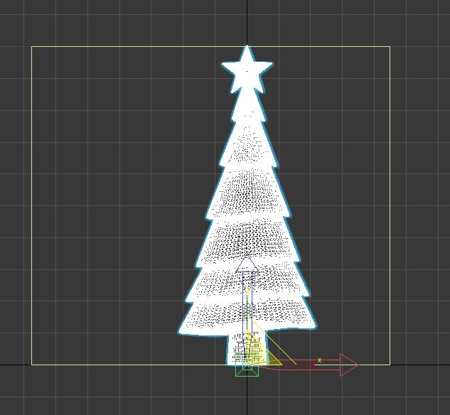
Slice the model.
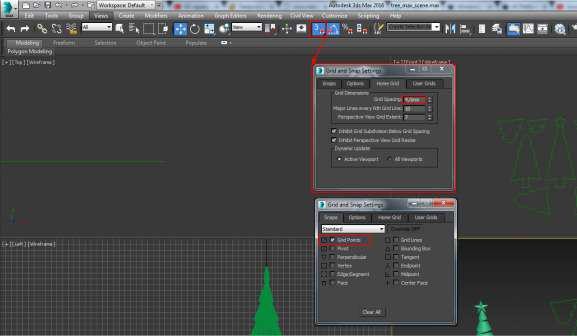
Set the grid spacing equal to the layer thickness. Right-click the Snaps toggle button. In the Grid and Snap Setting dialog window find the Home Grid tab, and set the Grid Spacing at 4mm; In the Snaps tab check the Grid Points checkbox.
To enable bindings, left click the Snaps toggle button. The button gleams blue.
Create a section in the front view Create> Shapes> Section. On the top view place the section plane in front of the model. Move the plane one square to the model and click the Create Shape button. In the Modify tab of the toolbar shift the plane one by one square by clicking Create Shape until you have done the whole model.
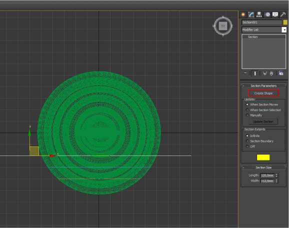
You will get something like this:
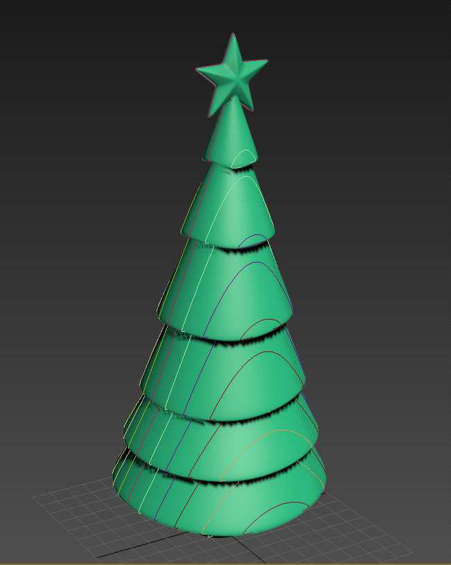
Hide the fur-tree. Select the resulting curves and apply the Extrude modifier to them.
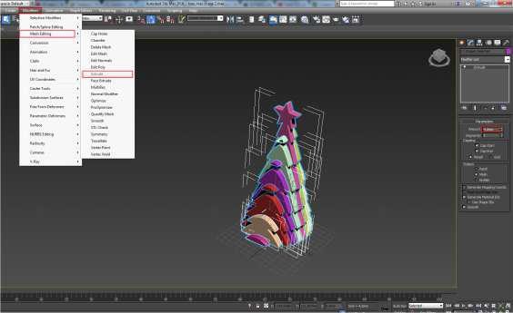
Delete the extra outlines.
Select one layer and click Editable Spline in the modifiers. Click the 3 key to shift to the spline selection mode. Delete the extra outlines.
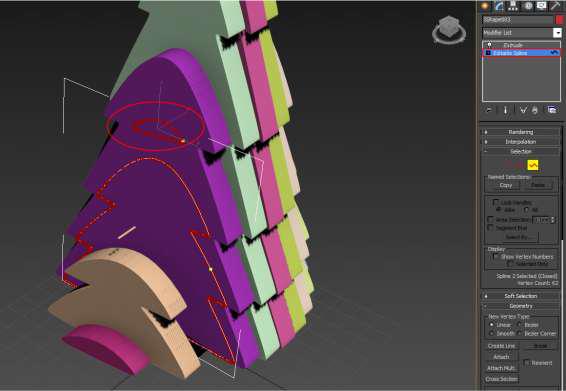
Save the outlines for the G-code generation.
Select all the layers and delete the Extrude modifier. To do it right click in the modifier stack and choose Delete in the context menu.
Position all the outlines in one plane, get them together and enclose in a frame 160х160 mm.
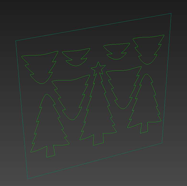
Export the outlines to DXF.
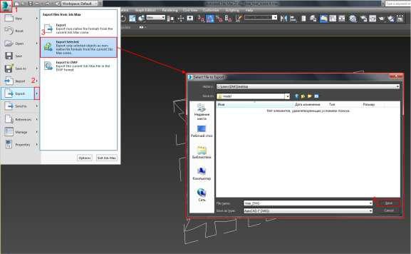
Select all the outlines and click the application button> Export> Export Selected. In the Save as type choose AutoCAD (*.DXF). The export parameters leave as default.
For G-code generation use Inkscape (https://inkscape.org/ru/download/)
and JTP Laser Tool. (https://jtechphotonics.com/?page_id=1980)
As Inkscape doesn’t support DXF, convert it to SVG using the free online service https://www.dxfconverter.org
Run Inkscape. Set mm as measurement units.
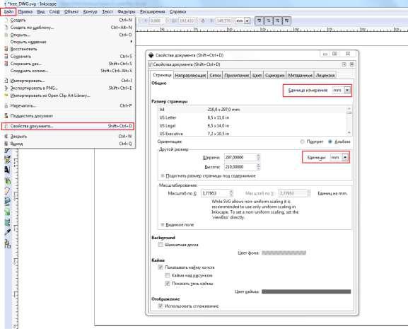
Import your outlines.
It is possible to drag the SVG file to the Inkscape canvas. To see the outlines set their thickness greater than 0, at 0,1 mm for example.
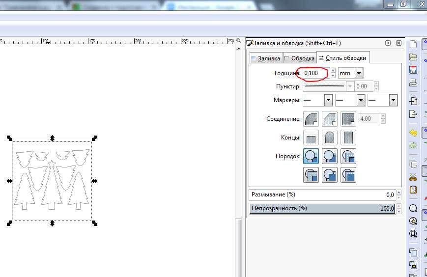
To bring the size of the outlines to the real ones create a rectangle similar in size to the frame around the outlines, i.e 160x160mm. Now scale the frame with the outlines so that the frame coincides with the rectangle. Remove the frame and the rectangle.
Now generate the G-code.
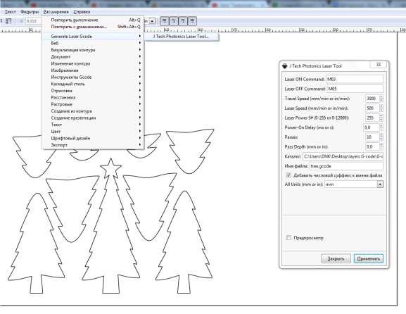
Go to Extensions> Generate Laser Gcode> JTech Photonics> Laser Tool.
Laser ON Command, Laser OFF Command; Travel Speed is the speed with the laser off; Laser Speed is the speed with the laser on; Laser Power (255 corresponds to 100% of the power); Power On Delay is the delay of the laser start; Passes is the number of the laser passes; Pass Depth is the laser downshifting after each pass.
Specify in the Catalogue where to save the G-code to.
To start the G-code generation click Apply. Shortly you will see the G-code file there.
Enjoy laser cutting with Endurance!
