Endurance laser box – an advanced driver for your laser diode (LD) or laser diode array
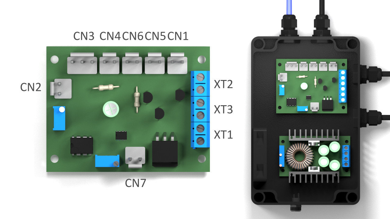
CN1 – Power Board +12V
CN2 – Analog Input/Inverted input
CN3 – Mode select switch SW1
CN4 – PWM Input
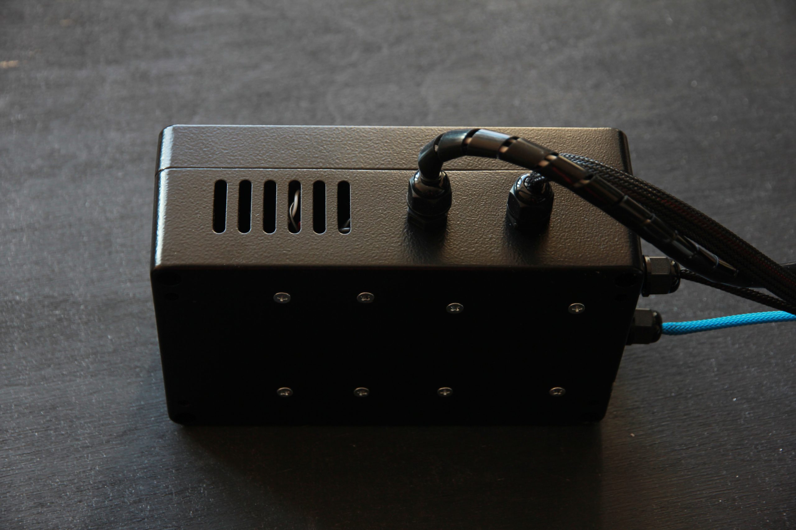
CN5 – Fan
CN6 – Input Voltage Voltmeter
CN7 – DC-DC output voltage voltmeter
XT1 – DC-DC
XT2 – Laser
XT3 – Laser current measurement. Ammeter


Control unit specifications
Load voltage:1.2V
Load currenе: 6A
Control: PWM signal
Voltage: 3-24V
Frequency: 90Hz-50kHz
Working cycle: 0-99.9%
Output signal to load: PWM
Frequency: Same as PWM input
Working cycle: Similar to PWM input signal
analog signal: Voltage 0-10V
Output signal to load: PWM
Frequency: 500Hz
Working cycle: 0-99.9%
Full power mode
Output signal to load: PWM
Frequency: 500Hz
Working cycle: 99.9%
Energy consumption: DC 12V 5A
Current stabilizer module cooling system
Cooling type: Peltier element
Temperature control: Thermal relay
Energy consumption: DC 12V 5A
Oscilloscope data (system test results)
Voltage under the load
Load voltage at idle. Vertical resolution 0.5V, horizontal 1ms.


The voltage on the load in the “Full power” mode – a PWM signal of 500Hz 98% is generated. Vertical resolution 0.5V, horizontal 1ms.


Yellow signal PWM 100Hz, duty cycle 50%, voltage resolution 2V. Red signal – load, voltage resolution 500mV. Sweep 500µs.


PWM operation, Voltage rise, 50µs sweep.


PWM operation, Voltage rise, 50µs sweep.


An attempt to make a current measurement through the shunt on a voltammeter:
Yellow signal PWM 100Hz, duty cycle 50%, voltage resolution 2V. Red signal – shunt, voltage resolution 100mV. Sweep 500µs.


Current rise, sweep 50µs.


Current drop, 50µs sweep.


General testing Endurance Laser box ver 2.0 mod report
Two resistors with a total resistance of 0.2 Ω were used as a load.
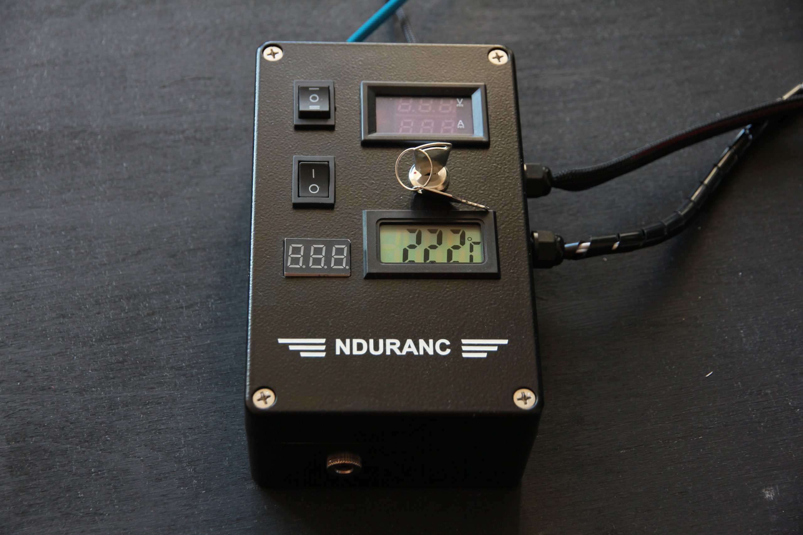
The room temperature is 22 degrees.
The temperature control on the current stabilizer is set to 25 degrees.
At the start of the system, the current is 5.95A. In the process of heating the transistor, the current can drop to 5.8A.
The system is working. Everything is controlled through the MO2 board. On a load at a voltage of 1.22V, the current is 6A.
The control box requires a 12V power supply and a minimum of 5A. Another same power supply is required for the cooling system of the current stabilizer. You can use a common power supply – the main thing is that its power is at least 60W.
A cable in a black braid with six wires at the output comes out of the control unit on the left side.
Thick black and red wires are connected to the laser diode (red wire – “+”, black – “-” (GND).
The thin red and black wires marked “OUT 12V” are the wires used to connect the laser diode cooling fan. After turning on the control unit, 12V is constantly supplied to them.
The remaining two wires are used to connect the temperature sensor to the thermometer installed in the control unit. The other end of these wires is inside the control unit and is not connected anywhere.
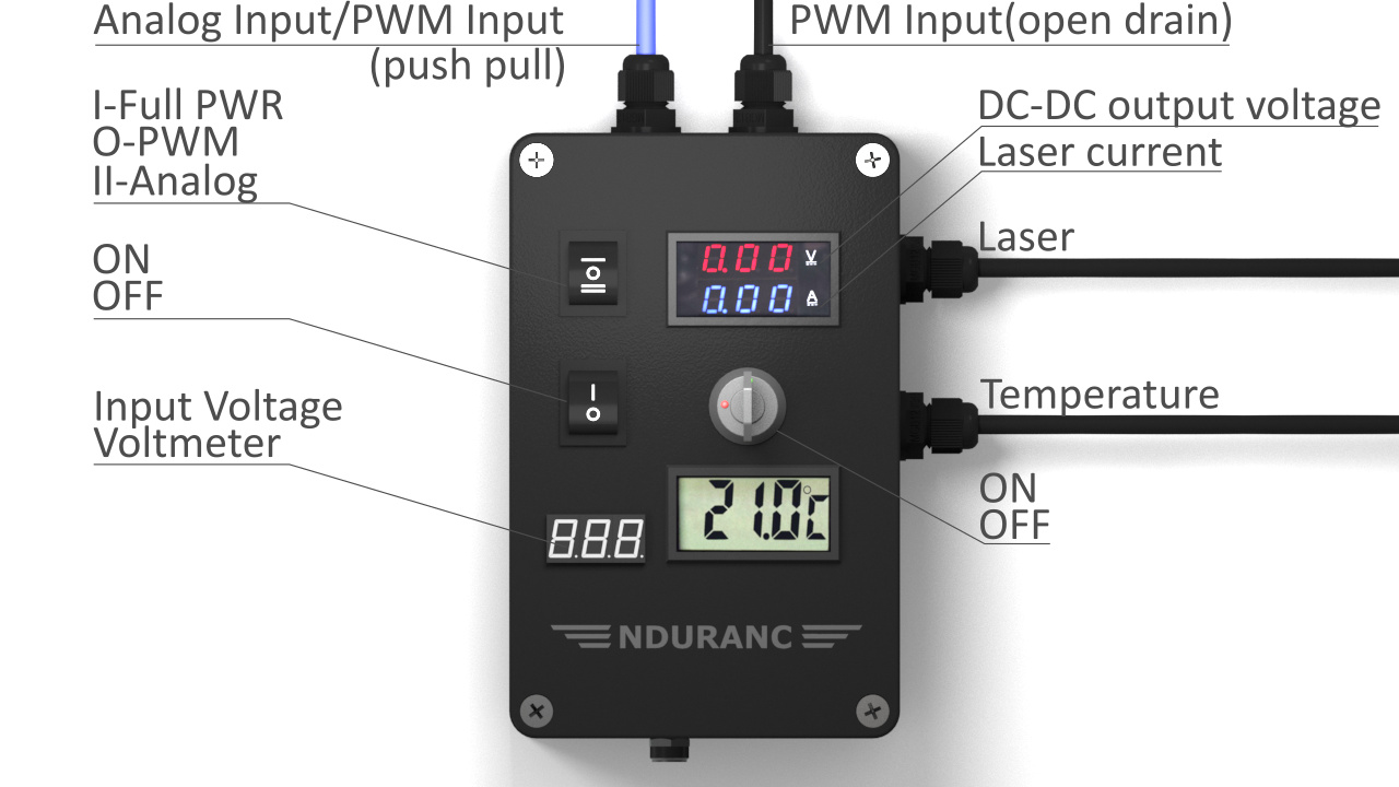
From above, two pairs of wires in blue and black braids come out of the control unit. These wires are designed to supply a control signal to the control unit (red wire – “+”, black – “-” (GND).
Wires in a blue braid are used for the PWM control signal – voltage 3.3-12V and frequency 90Hz-50kHz. Maximum duty cycle 99.9%. Also, these wires are used for control using an analog signal with a voltage of 0-10V (0-100%).
The black braided wires are used for the 12-24V PWM control signal.
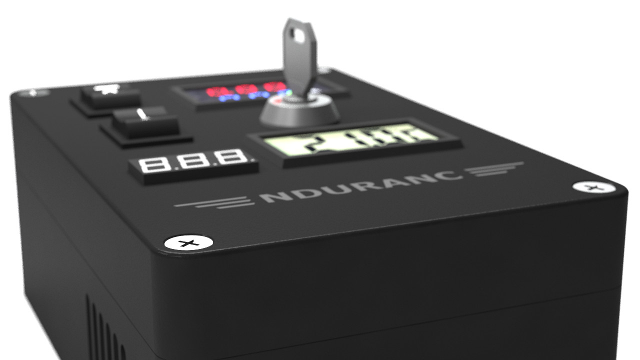
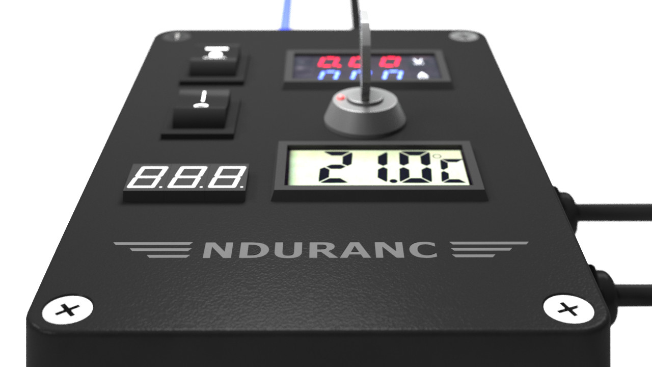
The following control elements are located on the control unit:
Voltmeter – shows the input voltage.
Thermometer.
Voltammeter – shows the output voltage and current.
Controls:
Two-position button – is responsible for turning on / off the control unit.
Key switch – connected in series with the shutdown button and is an additional safety measure against accidental activation of the control unit.
The three-position button is responsible for switching the operating modes of the control unit:
Position “I” – Mode “Full power”. In this mode, the laser diode is constantly on at full power and is not controlled in any way.
Position “0” – Mode “PWM”. In this mode, the laser diode is controlled by a PWM control signal.
Position “II” – Mode “Analog”. In this mode, the laser diode is controlled by an analog signal.
The output signal from the control unit to the laser diode is a PWM signal with a frequency and duty cycle corresponding to the PWM control signal in the case of the “PWM” mode.
In “Analog” mode, the signal frequency is 500Hz and the duty cycle depends on the voltage of the analog control signal.
In “Full power” mode, the signal frequency is 500Hz and the duty cycle is 99.9%.
There is also a mode that is used to focus the laser. It is similar to “Full power” mode with the only difference being that the PWM output signal duty cycle is 0.1%. This mode is activated as follows: with the control unit turned off, you need to set the three-position button to position “I” and only then turn on the control unit. The mode will be enabled until the three-position button is switched to another position.
There is a thermal relay on the cooling unit of the current stabilizer, which sets the temperature for turning on the cooling system (Peltier element) so that the stabilizer does not overcool to the state of condensate. The upper temperature indicator on the thermal relay is the current temperature on the temperature sensor, the lower temperature indicator is the set temperature, when it is exceeded by one degree, cooling will turn on (if the temperature is lower, then cooling will turn off). The temperature is set by pressing the upper button on the thermostat, after which the lower temperature indicator will flash. The upper and lower buttons set a higher or lower temperature. If, when setting the temperature, the buttons are not pressed for 2-3 seconds, the set temperature is saved in the settings.
An Endurance Laser box ver 2.0 (mod)