")
![]()
![]()
![]()
![]()
![]()
![]()
![]()
![]()
Preface
Thank you for using the Q-Switched Pulsed Fiber Laser (MFP 5W-70W) Series products from Maxphotonics. We compile this document for you in order that the laser is used and maintained properly. Due to the limited level of the translaters, coupled with time constraints, there are some careless mistakes in this document, and your understanding will be much appreciated. Thank you again for using Maxphotonics’ products.
Please take time to read and understand this User’s Guide and familiarize yourself with the operating and maintenance instructions before you use the product. We recommend that the operator read the Section titled “Safety Information” prior to operating the product.
This User’s Guide should stay with the product to provide you and all future users and owners of the product with important operating, safety and other information.
We identify the parts to which you need to pay special attention in the document with underscore. Please notice those information to prevent the unnecessary damages.
Company Profile
Found in 2004, Maxphotonics is one of the first fiber laser manufacturers in China. It is also the first in China to realize independent intellectual property rights and vertical integration in the core technologies of fiber lasers and optical devices. One of the national high-tech enterprises. Maxphotonics has developed into an internationally renowned laser manufacturer that develops, manufactures and sells fiber lasers and core optical components.
Black Friday Brilliance: Top Laser Heads on Sale!
Maxphotonics specializes in the research, development, production and sales of
fiber lasers, including pulsed fiber lasers, continuous fiber lasers and direct diode
lasers. It also implements pump sources, combiners, fiber gratings, isolators, laser output heads, and stripping. Optical devices such as molds, acousto-optic modulators, and pattern matchers are produced autonomously. Products are widely used in marking, engraving, cutting, drilling, cladding, welding, surface treatment, rapid prototyping and additive manufacturing processes.
Characteristic Explain
reliability, and high performance on marking and engraving, which makes them ideal tools in this area.
Maxphotonics’ Q-Switched Pulsed Fiber Laser (MFP 5W-70W) Series are Class 4 laser products and are designed and tested with safety. By following this User Guide and applying sound laser safety practices, it will be a safe and reliable device.


Laser light exhibits unique characteristics that may pose safety hazards. Therefore, the laser light can’t be normally associated with other light sources, and all operators and people near the laser must be aware of these special hazards.
In order to ensure the safe operation and optimal performance of the product, please follow all warnings and safety instructions in this guide during process of operation, maintenance and service.
For ensuring the safety of operators, operators are urged not to open the equipment privately at all times. There are no user serviceable parts, equipment or assemblies associated with this product. Lasers of unauthorized disassembly shall not be subject to warranty.
Safety Conventions
All safety warning symbols during operating process of the laser include:
| SYMBOLS | DESCRIPTION |
| WARNING : Refer to a potential Electrical Hazards to human body; It requires certain procedures; otherwise, it may result in bodily harm to you and/or others. In order to ensure the personal safety of operators, do not violate the requirement of the WARNING sign. | |
| CAUTION : Refers to a potential hazard on product. It requires certain procedures; otherwise, it may result in damage to the product or components. In order to ensure normal use of equipment, do not violate the requirement of the CAUTION sign. | |
| WARNING : Refers to a potential Laser Hazard. The symbol represents laser radiation. The symbol is pasted on laser output end. | |
| NO SYMBOL | IMPORTANT : Refers to any information regarding the operation of the product. Please do not overlook this information. |
NOTE :
◎ This product is classified as a Class IV laser product. This product emits light with a wavelength of about 1064nm up to 5W / 10W / 20W / 30W / 50W / 70W, which is not in the visible range, but these beams may cause irreversible damage to the retina and cornea. Chuangxin Laser recommends that you always wear qualified and safe protective glasses when operating the laser.
Laser Protection
Laser Protection Requirements
You must wear the safety protective glasses while operating the laser, and rationally select the safety protective glasses according to the lasing wavelength of the laser. If the device is a tunable laser or Raman product, it emits light over a range of wavelengths and the end user should confirm the laser safety eyewear used protects against light emitted by the device over its entire range of wavelength.
Laser Protective Equipment Suppliers
Maxphotonics recommends material or equipments provided by following laser protective equipment suppliers for you, including LaserVision USA, Kentek Corporation, Rochwell Laser Industries, etc. All the supplier information is provided by Maxphotonics only for the convenience to use, so Maxphotonics assumes no responsibility for any problem caused by using the products of abovementioned suppliers.
General Safety Instructions
In order to ensure the safe operation and optimal performance of the product, please follow these warnings and cautions in addition to the other information contained elsewhere in this document.
Specular Reflection
There are often numerous secondary laser beams produced at various angles in the output port of the laser. These divergent beams are produced when the primary beam of laser reflects off a smooth surface, and they are called specular reflections. Although these secondary beams may be less powerful than the total power emitted from the primary beam, the intensity may be great enough to cause damage to the eyes and skin as well as surface of materials.
WARNING :
◎ You must exercise caution to avoid/minimize specular reflections as these laser radiations are invisible!
Safety Instructions of Accessories
WARNING :
◎ This device has an output optical head connected to the laser by a fiber cable.
Please, be careful dealing with the output head.
Optical Operating Instructions
We strongly recommend that you read the following procedures before operating the laser:
- When the power is turned on, do not look directly into the laser light exit hole;
- Avoid placing the laser and related optical output devices on the same horizontal line as the eyes;
- Reasonably select safety protection equipment according to the output power and wavelength requirements of the laser to ensure the safety of operators;
- Do not install the sight when the laser is working;
- Please make sure to use the sight when the laser is off (such as when installing the sight on the fixture or observing the end face with optical
instruments).
- Please use the defocus method to mark on the high-reflection material, otherwise the laser will be directly damaged.
- For collimated output, please do not touch the output lens or any solvent for cleaning. Use lens tissue paper to clean the output lens. After use, please replace the protective cover of the sight.
WARNING :
◎ Make sure that the individual protective equipment meets the output power and wavelength range of the laser.
◎ Never look directly into the optical fiber or the collimator, and Use appropriate
laser safety eyewear when operating this device.
◎ Optical damage may result from failure to comply with the above instructions. Such damage is not covered by the warranty.
WARNING:
◎ Use of controls or adjustments or performance of procedures other than those set forth in this User’s Guide and related documents may result in hazardous radiation exposure.
Electrical Operating Instructions
Q-Switched pulsed fiber laser (MFP 5W-70W) Series supply voltage:24VDC.
| Cable Color | Supply |
| BROWN | +24VDC |
| BLUE | GND |
| YELLOW-GREEN | SHELL |
WARNING :
◎ Please ensure that the equipment case is well grounded. Interruption at any point in the ground loop may cause personal injury. The interruption of the power supply voltage is very dangerous to the equipment. Please provide a continuous and uninterrupted power supply voltage.
◎ Before powering the laser, please make sure that the DC power supply voltage (24VDC) is used correctly and the wiring is correct. Any wrong wiring method may cause injury to personnel or equipment;
◎ Before turning on the laser, please check whether the voltage is normal.
◎ This product has no parts, components or components that need to be repaired by the user. All maintenance work must be completed by professionals of Chuangxin Laser;
◎ In order to avoid short circuit, please do not remove the case, disassemble the laser and damage related labels without authorization, there will be danger of electric shock or burns, and any product disassembled or tampered with by yourself will no longer enjoy the warranty right.
- Environment Conditions and Precautions
We strongly recommend that you read the following procedures before operating the laser:
- Do not expose the device to a high moisture/high temperature environment. Install the laser in the cabinet with the function of temperature-humidity control
and dust-free.
- Laser Module has three fans at the rear panel for active cooling. Make
sure that there is at least 5cm between fan protector and external objects, and
with sufficient airflow to cool the device.
- Before switching on the device make sure that environmental temperature
and humidity are within a specified range.
WARNING :
◎ Optical damage may result from failure to comply with the above instructions. Such damage is not covered by the warranty.
- Routine Maintenance
- Avoid the impaction on the shipper rod of worktable when the laser is working.
- The laser and optical lens are fragile, please handle with care.
- Stop running once device failure, and provide professional treatment.
- Please follow a set sequence of on-off.
- The limitation on surface of marking machine is within the working area.
- Keep the device clean and indoor.
- Safety Labels and Labeling Locations
The following shows the pictures of tags and their positions on the product:
| Pictures of label | Label name | Label location |
 | Light Emission | Top Cover |
| CAUTION | Top Cover |
Additional Safety Information
For additional information regarding Laser Safety, please refer to the list below:
Laser Institute of America(LIA) 13501 Ingenuity Drive, Suite 128
Orlando,Florida 32826
Phone:407 380 1553,Fax: 407 380 5588
Toll Free:1 800 34 LASER
American National Standards Institute
ANSI Z136.1, American National Standard for the Safe Use of Lasers (Available through LIA)
International Electro-technical Commission IEC 60825-1,Edition 1.2
Center for Devices and Radiological Health
21 CFR 1040.10 – Performance Standards for Light-Emitting Products US Department of Labor – OSHA
Publication 8-1.7 – Guidelines for Laser Safety and Hazard Assessment. Laser Safety Equipment
Laurin Publishing
Laser safety equipment and Buyer’s Guides
Property Introductions
Product Description
The MFP acousto-optic Q-switched fiber laser uses a Q-switch (Photoelectric switch) main oscillator and a high-power fiber amplifier (MOPA). The emission wavelength is 1064nm, and the operating parameters are set through the 25Pin control interface, which is suitable for laboratory and industrial applications. Convenient operation, overall maintenance-free, can be directly integrated into user equipment. Multi-power optional, compact structure, fiber optic isolator output, ideal laser source for laser marking industry. The optical head has an optical isolator with a certain degree of isolation, which can be directly applied to low-reflection materials (such as plastic, wood, paper, etc.) and marking of metals with low reflectivity.
Main Features:
- Short optical pulses, high peak power, a wide range of PRR.
- Superior reliability, long lifetime.
- No shadow or virtual open circuit phenomenon when processing on special materials.
- Universal DB-25 interface.
Applications:
- Industrial applications
- Scientific research
Laser Model Designation Codes
| Model | Model Coding Rules |
| MFP-5W | Maxphotonics Q-Switched Pulsed Fiber Laser 5W |
| MFP-10W | Maxphotonics Q-Switched Pulsed Fiber Laser 10W |
| MFP-20W/H/X/L | Maxphotonics Q-Switched Pulsed Fiber Laser 20W |
| MFP-30W/H/X/L | Maxphotonics Q-Switched Pulsed Fiber Laser 30W |
| MFP-50W/H | Maxphotonics Q-Switched Pulsed Fiber Laser 50W |
| MFP-70W | Maxphotonics Q-Switched Pulsed Fiber Laser 70W |
Certification
Maxphotonics certifies that this equipment has been thoroughly tested and inspected and meets published specifications prior to shipping. Upon receiving your equipment, check whether the packaging and accessories have been damaged in transit. If damage is apparent, please contact Maxphotonics immediately.
Optical Characteristic Parameters
Specification
| NO. | Characteristics | Test Conditions | Min. | Typical | Max. | Unit |
| 1 | Mode | Pulse | ||||
| 2 | Polarization | Random | ||||
| 3 | Beam Quality M² | MFP-5W/10W/20X/20L/ 20W/30X/30L | 1.2 | 1.4 | 1.5 | |
| MFP-20H/30W/30H /50W/50X/50H/70W | 1.3 | 1.6 | 1.8 | |||
| 4 | Center Wavelength | Pout=Pnom | 1060 | 1064 | 1070 | nm |
| 5 | Spectrum Width(3dB) | Pout=Pnom | 5 | 5 | 10 | nm |
| 6 | Average Optical Power(Pnom) | MFP-5W | 4.5 | 5 | 5.5 | W |
| MFP-10W | 9.5 | 10 | 10.5 | |||
| MFP-20X | 18 | 18.5 | 19 | |||
| MFP-20L | 18.5 | 19 | ||||
| MFP-20W/H | 20 | 20.5 | 21 | |||
| MFP-30X | 24 | 24.5 | 25 | |||
| MFP-30L | 29 | 29.5 | 30 | |||
| MFP-30W/H | 29 | 30 | 31 | |||
| MFP-50W/H | 49 | 50 | 51 | |||
| MFP-70W | 69 | 70 | 71 | |||
| 7 | Power Range | 10 | 100 | % | ||
| 8 | Single pulse energy | MFP-5W | 0.5 | mJ | ||
| MFP-10W | 0.45 | |||||
| MFP- 20W/20L/20X/30L/30X | 0.65 | 0.68 | 0.75 | |||
| MFP-20H/50W/30W | 1 | |||||
| MFP-30H/70W/50H | 1.4 | 1.45 | 1.5 | |||
| 9 | Optical Pulse Width(FWHM) | MFP-5W | 80 | 100 | 120 | ns |
| MFP-10W | ||||||
| MFP-20W/H/X/L | ||||||
| MFP-30W/H/X | ||||||
| MFP-50W/H/X | ||||||
| MFP-30L | 100 | 120 | ||||
| MFP-70W | 100 | 140 | ||||
| 10 | Pulse Repetition Frequency (PRF.) | MFP-5W | 10 | 30 | KHz | |
| MFP-10W | 20 | 60 | ||||
| MFP-20L/20X | 27 | 60 | ||||
| MFP-20H/30H | 20 | 80 | ||||
| MFP-30L | 40 | 60 | ||||
| MFP-30W/30X/20W | 30 | 60 | ||||
| MFP-50W | 50 | 80 | ||||
| MFP-50H | 33 | 80 | ||||
| MFP-50X | 46 | 60 | ||||
| MFP-70W | 50 | 170 | ||||
| 11 | Output Power Stability | Pout=Pnom | 3 | % | ||
| 12 | Beam Diameter 1/e2 | MFP-5W | 6 | 8 | mm | |
| MFP-10W | 6 | 8 | ||||
| 20L/20X/20W/20H | 6 | 8 | ||||
| 30L/30X/30W/30H | 6 | 8 | ||||
| 50X/50W/50H/70W | 6 | 8 | ||||
| 13 | Beam Ellipticity | 90 | % | |||
| 14 | Delivery Cable Length | MFP-5W/10W/20X/ 20L/20W/20H | 1.9 | M | ||
| MFP-30X/30L/30W/30H | 1.9 | |||||
| MFP-50W/50H/70W | 3 | |||||
| 15 | Laser startup Time | Pout=Pnom, 10%~90% | 110 | 140 | us | |
| 16 | Laser Shutdown Time | Pout=Pnom, 90%~10% | 110 | 150 | us | |
| * For reference only. Other beam diameter available by order. | ||||||
General Characteristic Parameters
| NO. | Characteristics | Test Conditions | Min. | Typical | Max. | Unit |
| 1 | Operating Environment Tem. | 10 | 42 | ℃ | ||
| 2 | Storage Temperature | -10 | 60 | ℃ | ||
| 3 | Cooling | Air-cooling | ||||
| 4 | Warm Up Time | -Operate | 1 | min | ||
| -Stable | 10 | min | ||||
| 5 | Operating Environment humidity | 10 | 95 | % | ||
| 6 | Dimensions | Standard Edition | 345.5×266.2×120 | mm | ||
| Small version | 287×219×94.61 | mm | ||||
| 7 | Weight | MFP-5W | 7.5 | kg | ||
| MFP-10W | 10 | |||||
| MFP-20W/X/L | 10 | |||||
| MFP-30W/H/X/L | 12 | |||||
| MFP-5W Small version | 7 | |||||
| MFP-10W Small version | 7 | |||||
| MFP-20W/H/X/L Small version | 7 | |||||
| MFP-30X/L Small version | 7 | |||||
| MFP-50W/H/X | 12 | |||||
| MFP-70W | 12 | |||||
| 8 | Power Supply | 23 | 24 | 25 | VDC | |
| 9 | Power Consumption | MFP-5W | 90 | W | ||
| MFP-10W | 120 | |||||
| MFP-20W/H/X/L | 150 | |||||
| MFP-30W/H/X/L | 240 | |||||
| MFP-50W/H/X/L | 360 | |||||
| MFP-70W | 450 | |||||
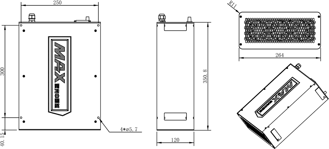
Structural Layout
Q-Switched Pulsed Fiber Laser Small version dimensions (Unit mm):

Q-Switched Pulsed Fiber Laser 50W-70W dimensions (Unit mm):
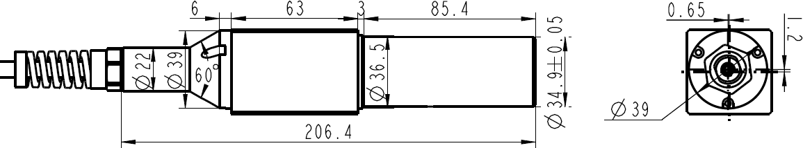
Laser isolator output head dimensions are shown below (Unit mm):
Operation Guide
Packing List :
| Contents | Quantity |
| User Guide+ Qualified Test Result | 1 |
| Power Wire (Optional) | 1 |
CAUTION :
◎ If any damage of the external package and internal parts has been found upon receipt of product, please contact Maxphotonics Co., Ltd. or designated agent immediately.
Electrical Power Connection
Power wire
◎ The main power supply (24VDC) must be able to provide continuous
operating current (see detailed specifications in Chapter 4) and
Peak current higher than 50% in 250us short cycle. Most types of lasers have a current loss of less than 10A, so their peak current loss is less than 14A.
◎ The power supply should maintain a stable voltage and be within the specified
range (see Chapter 4 for detailed specifications). If the up and down fluctuations of the power supply voltage exceed the specification range, the laser operation will be unstable. Please pay attention to the transient load variation rate of the power supply and choose an appropriate power supply type.
◎ When the main power of the laser is connected, the voltage drop (especially
the peak current loss) caused by the length and cross section of the laser’s own power cord can be ignored.
◎ The 24VDC main power supply must have a floating output, and its return line
can only be connected to the laser power line (blue). Incorrect connection may cause current loops to fail.
◎ The laser ground (DB25 Pin10-15,24) and the laser 24VDC power return
line (blue line) are connected to the inside of the laser module, and the external interface of the laser module is not allowed to be connected.
◎ The common ground inside the module is connected to the laser case through
a 470 ohm resistor and a 47nF capacitor in parallel. This network is used to balance the voltage difference between the ground and the laser case.
◎ According to the design, the ground of the control card may be connected to
the ground; otherwise, the ground of the control circuit is floating, indicating that the blue and yellow-green wires of the 24VDC power cable of the laser are not connected (see the red dotted line in the electrical connection diagram in this chapter for details) .
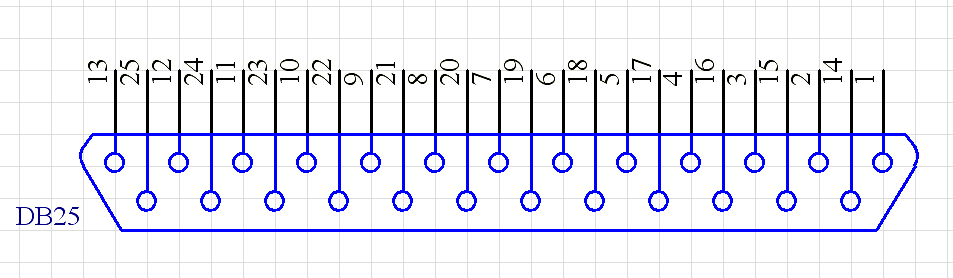
Control Connector Pin Assignment, DB-25 Plug
Pin Function
All control pins are TTL compatible, unless otherwise noted in the pin description. For the interface designs level ranges of the TTL standard should be taken into consideration.
| Pin# | Description | ||
| 1-8(D0-D7) |
| ||
| 9 | Latch (Latches power setting into the laser by the rising edge) | ||
| 10-15 | Ground | ||
| 16,21 | Laser alarms | ||
| Pin16 | Pin21 | Situation | |
| L | L | Out of the specified range of operating temperature | |
| L | H | Normal | |
| H | H | MO abnormal | |
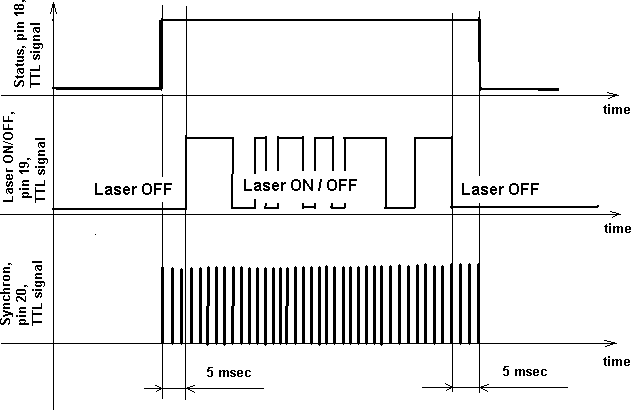
| 18 | Master Oscillator(MO) signal:
| ||
| 19 | Booster signal (ON/OFF input)
| ||
| 20 | Pulse Repetition Rate (Synchronization) input Refer to PRR range. Allowed duty cycle is 0.1~0.9. |
| 22 | Guide Laser (red diode) ON/OFF input
|
| 23 | Emergency Stop Input
|
Digital Control Interface (DB-25) Description
- The laser is controlled via signals applied to the DB-25 connector. Please refer to the connector interface description table above for 5.2.1 pin designation
and operating levels.
- Pins 1 to 8 are the 8 bit bus for the output power setting. Pin 1 is the least
significant bit and pin 8 is the most significant bit. Codes in the range 0…255 (0…FFh) should be applied to these pins, which correspond to the power setting of 0…100% of the specified nominal value, such as:
| Set 1 | Set 2 | Set 3 | Set 4 | Set 5 | |
| Pin 1 | 0 | 0 | 0 | 0 | 0 |
| Pin 2 | 0 | 0 | 0 | 0 | 0 |
| Pin 3 | 0 | 0 | 0 | 0 | 0 |
| Pin 4 | 0 | 0 | 0 | 0 | 0 |
| Pin 5 | 0 | 0 | 0 | 1 | 1 |
| Pin 6 | 0 | 0 | 1 | 1 | 1 |
| Pin 7 | 0 | 1 | 1 | 1 | 1 |
| Pin 8 | 1 | 1 | 1 | 1 | 1 |
| Current | 50% | 75% | 87.5% | 93.75% | 100% |
| Laser Power | 35% | 65% | 85% | 92% | 100% |
- Pins 16 and 21 are the alarm and status outputs. These pins indicate the following device states:
| Pin16 | Pin21 | Alarm description |
| L | L | Laser temperature is out of the operating temperature range. |
| L | H | Normal Operation |
| H | H | MO Alarm |
- Pin 18 is the Master Oscillator (MO) signal. The MO should be switched ON at least 5ms earlier than the Booster (BS) is switched ON. Once the MO is
switched ON, the laser starts to consume more electrical power.
- Pin 19 is the Booster control input. HIGH means switching the BS on and
LOW means switching it OFF. The laser starts to emit light within specified delay
time after the pin 19 is set HIGH and stops emitting when the pin 19 is set LOW.
CAUTION :
◎ The MO should be switched ON at least 5ms earlier than the BS is switched ON. The laser does not start to emit if you switch the BS ON while the MO is LOW/OFF.
◎ If the MO is switched ON later than the BS is switched ON, the laser will emit about 1ms later than the switching of the MO. It is abnormal operation which should be avoid and not listed in the user guide. The BS switches ON simultaneously with the rising edge of the signal applied to the pin 19.
(6)Pin 20 is the Synchronization input. Pulse train with a repetition rate (PRR)
within specified operating range should be applied to the pin 20 (refer to the optical specification for PRR limits). The laser emits pulses simultaneously with the rising edge of the signal.
CAUTION:
◎ If the PRR is out of the specified range (or no PRR signal is supplied) the
laser safety circuit will substitute the missing pulses or limit the PRR.
◎ The laser emission is not allowed simultaneously with the guide laser. The BS is blocked internally during the guide laser operation. If pin 19 is set HIGH but the guide laser is on, the laser will not emit light, unless the guide laser is switched OFF. The MO is able to be switched ON or OFF during the guide laser is ON.
(7)Pin 23 is the “Emergency stop” input. It should be set to HIGH for normal operation. In case of dropping this pin to LOW state (even for a short period of
time), the laser automatically switches OFF (similar to the state when both MO and BS are OFF). It is necessary to drop both MO and BS to LOW (if they were HIGH) before restarting the laser.
Laser Operation
1. Steps
All control pins are TTL compatible, unless otherwise noted in the pin description. For the interface designs level ranges of the TTL standard should be taken into consideration.
- Remove the protective cap from the laser output head;
- Connect the control system with the laser DB25 pin interface. For the pins to be used, refer to 5.2.2 Digital Control Interface (DB-25) Function Description;
- Recommended initial state of control needle:
Pin18,19, pin is low
Pin20 repetition frequency is within the specified range
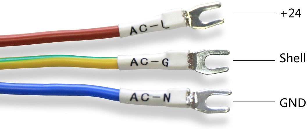
- Connect the 24VDC power supply to the laser power cable (+ 24V corresponds to red, the ground wire is connected to yellow, and the negative pole is connected to the black wire);
- After the laser is powered by 24VDC, it can be operated.
CAUTION:
◎ Please allow 24VDC main power before initializing the control signal.
- Set the emergency stop input (Pin23) to H level;
- Set the desired power from Pin1 ~ 8;
- Set Pin18 to H level and turn on MO;
- Wait for 5ms;
- Fast modulation of the laser by Pin19. Enter the H / L level to control the laser on and off. The rise / fall time of the laser switch has been limited (see Chapter 4 for detailed specifications). The speed of modulation cannot be faster than the sum of rise and fall times. Typical rise / fall time is 250us, and its modulation period should be greater than 500us (corresponding frequency is 2kHz);
- After completing the operation of the laser switch and waiting for the next task, if the time exceeds 20ms, it is recommended to turn off the MO, which will reduce power consumption, extend the life of the MO, and avoid the residual power output of the MO;
- Turn off BS and MO after completing a task (Pin18 and Pin19 are set to L level)
- Disconnect the 24VDC power supply.
2. Job characteristics
- During laser operation, PRR can be changed through Pin20. When changing the PRR, please note that the time between two adjacent rising edges must not be greater than the cycle time of the lowest PRR frequency. For a laser with a minimum repetition frequency of 20kHz, it should not be greater than 50us. Otherwise, the protection circuit will automatically add missing pulses. If the PRR is greater than the specified maximum repetition frequency, the protection circuit limits it to the maximum value.
- It is allowed to change the power settings of Pin1 ~ 8 during laser operation and store it in the laser. The laser will respond to the changed power setting during the specified rise time.
- If Pin18 is at H level and Pin19 is at L level, there will be laser output below 20mW working wavelength.
- If the temperature of the laser module exceeds + 45 ° C, the laser will automatically turn off, and at the same time at Pin16 and
Pin21 outputs the corresponding alarm signal. If the temperature drops below
+ 45 ° C, the laser will not automatically resume working, and keep the alarm signal unchanged, restart the operation.
Common Boards And Parameter Settings
MFP acousto-optic Q-switched fiber lasers reflect high-speed and high-efficiency capabilities, so it is required to configure high-speed galvanometers as much as possible to reflect their performance advantages.
| name of software | SAMlight | |||
| NO. | Name / Item | Set parameter value | Typical setting value | unit |
| 1 | Empty pen delay | 50 ~ 100 | Us | |
| 2 | Pen delay | 50 ~ 100 | Us | |
| 3 | Turning delay | 50 ~ 100 | Us | |
| 4 | Laser delay | -60 ~ -150 | Us | |
| 5 | Laser Delay Off | 60 ~ 150 | Us | |
| name of software | EzCad(bjjcz) | |||
| NO. | Name / Item | Set parameter value | Typical setting value | unit |
| 1 | End delay | 50 ~ 150 | Us | |
| 2 | Corner delay | 50 ~ 150 | Us | |
| 3 | Laser delay | -50 ~ -200 | Us | |
| 4 | Laser Delay Off | 20 ~ 150 | Us | |
| 5 | Laser Delay Off | 60 ~ 150 | Us | |
| name of software | MAX software | |||
| NO. | Name / Item | Set parameter value | Typical setting value | unit |
| 1 | Empty pen delay | 50 ~ 100 | Us | |
| 2 | Marking delay | 50 ~ 100 | Us | |
| 3 | Turning delay | 20 ~ 100 | Us | |
| 4 | Laser delay | -50 ~ -200 | Us | |
| 5 | Laser Delay Off | 50 ~ 150 | Us | |
| Recommended Supporting Models For Common Field Lenses | |||||||||||
| Field lens focal length | 20X | 20W | 20H | 30X | 30W | 30H | 30H | 50X | 50W | 50H | 70W |
| F=100 | A+ | A+ | A+ | A+ | A+ | A+ | A+ | A+ | A+ | A+ | A+ |
| F=160 | A+ | A+ | A+ | A+ | A+ | A+ | A+ | A+ | A+ | A+ | A+ |
| F=254 | A | A | A | A | A+ | A+ | A+ | A+ | A+ | A+ | A+ |
| F=330 | B | B | B | B | A | A | A | A | A | A+ | A+ |
| F=420 | C | C | C | C | C | B | B | A | A | A | A |
A +: The effect is very good, the laser is strong after focusing;
A: The effect is moderate, the efficiency is lower than the A + field lens;
B: The effect is general, suitable for materials that do not require high energy density;
C: The light is weak, and it is not recommended.
The above is the recommended combination of laser and field lens, for reference only.
CAUTION :
◎ Any driver software provided now or in the future is not the exclusive license of Chuangxin Laser. By using the software, you agree to the terms here.
◎ This driver software is protected by trade secret law, copyright law and international treaties. Chuangxin Laser reserves all rights. Device owners can only use driver software for product and program backup of Chuangxin Laser. Any change of driver software, Chuangxin Laser will not guarantee the equipment.
◎ For whatever reason or other special purpose, the provided driver software will not be changed and there is no warranty. Chuangxin Laser does not guarantee that the functions included in the software fully meet the needs of the user or the equipment, or that the operation of the driver software is uninterrupted or error-free. In response to user needs, Chuangxin Laser provides driver software to users, but it does not guarantee that all driver software has passed the normal quality control or product application of Chuangxin Laser. Chuangxin Laser assumes that you already have application knowledge in a particular language and does not provide support for end users. Chuangxin Laser may modify the driver software, but has no responsibility to release the latest version.
◎ In addition to the above-mentioned clear warranty terms, Chuangxin Laser refuses to provide the buyer with any other guarantees, including unlimited, any other tacit guarantees, such as infringement of freedom or other commercial purposes.
Common Fault Treatment
| Laser Troubleshooting Table | |||
| NO | Fault phenomenon | Check items | Troubleshooting steps |
| 1 | No laser | Power supply |
(connected to the laser) state. |
| Board |
| ||
| emergency switch | 5. Check whether the emergency stop switch (PIN23 pin) of the device is normal (the signal is high when the laser is working). | ||
| Marking software |
observe the parameters. | ||
| DB25 signal |
definition. | ||
| Red light confirmation | 11. If the red light signal is high, the red light output will be given priority. (If it is a built-in red laser, you can judge whether the laser light path is normal by detecting whether there is red light output). | ||
| Isolator | 12. Confirm whether the light spot of the isolator is normal (the light spot is round and there is no dark spot). | ||
![]()
![]()
Common Fault Treatment
| Laser Troubleshooting Table | |||
| NO | Fault phenomenon | Check items | Troubleshooting steps |
| 2 | Laser Weak | Working current confirmation | 1. Check whether the power supply is stable and the current reaches the rated working current. |
| Optical mirror confirmation |
collimator is contaminated. If it is contaminated, wipe it gently with absolute ethanol in front of it.
such as red beam combiner, galvanometer and field lens. | ||
| Service life confirmation | 4. The power is attenuated after the laser is used for 20,000 hours, which is normal power loss. | ||
| Signal interference | 5. There is a disconnection during the marking process, usually due to signal interference. For this reason, the weak and strong current leads cannot be tied together or on the same side. The signal line uses a signal line with a shielding function; Good contact. | ||
| Marking interface parameter confirmation | 6. Check whether the pulse width frequency has been set within the required range. | ||
| Optical path detection | 7. Confirm whether the light spot of the isolator is normal (the light spot is round and there is no dark spot). 8. Check whether the output light of the laser is blocked (make sure that the output end of the isolator and the galvanometer port are on the same horizontal line during installation). | ||
| 3 | Laser light is unstable | Power supply | 1. Check whether the power supply is stable and the current reaches the rated working current. |
| Signal interference |
interference cable, and the port is in good contact. | ||
| Laser temperature |
(reference ambient temperature 45 ~ 47 ℃ ) will appear light unstable.
temperature 45 ~ 47 ℃ ). | ||
| Laser Troubleshooting Table | |||
| NO | Fault phenomenon | Check items | Troubleshooting steps |
| 4 | Low power | Working current confirmation | 1. Check whether the power supply is stable and the current reaches the rated working current. |
| Optical mirror confirmation |
| ||
| Isolator |
| ||
| Service life confirmation | 6. It is normal power loss for the laser to lose power after 20,000 hours of use. | ||
| Signal interference | 7. There is a disconnection during the marking process, usually due to signal interference. For this reason, the weak and strong current leads cannot be bundled or walk on the same side. The signal line uses a signal line with a shielding function; Good contact. | ||
| Armor cable bending | 8. Check whether the bending of the armor cable is too small. | ||
| Marking interface parameter confirmation | 9. Check whether the pulse width frequency has been set within the required range (only for MOPA series). | ||
| 5 | Laser is not powered | Power confirmation |
|
| 6 | Abnormal light spot of isolator | Isolator spot confirmation |
|
| Laser Troubleshooting Table | |||
| NO | Fault phenomenon | Check items | Troubleshooting steps |
| 7 | Broken pen | Working current confirmation | 1. Check whether the power supply is stable and the current reaches the rated working current. |
| Signal interference | 2. There is a disconnection during the marking process, usually due to signal interference. For this reason, the weak and strong current leads cannot be bundled or walked on the same side. The signal line uses a signal line with a shielding function; Good contact. | ||
| Laser temperature | 3. Check whether the laser’s temperature is too high, and the temperature is close to the critical temperature (the reference temperature is 53 ℃ ). | ||
| Board | 4. Check whether the board wiring is correct and the contact is good. 5. Check whether the 19-pin signal (board output, control board input, sampling resistance signal) is normal through an oscilloscope. | ||
| 8 | Light leakage | Pre-current confirmation | 1. Check whether the light leakage power is between 15-20mW, and the pre-current needs to be adjusted if it exceeds. |
| 9 | Laser is not ready | DB25 check | 1. Check whether the DB25 cable is in good contact. |
| Laser status confirmation | 2. Check whether the laser is working. | ||
| 10 | High temperature alarm | Signal interference | 1. Detect whether there is interference in the surrounding signals. |
| Laser temperature | 2. If the temperature of the laser case is too high, the light will be unstable when the temperature is close to the critical temperature (reference temperature 53 ℃ ). | ||
| Troubleshoot PIN16 PIN21 | 3. PIN16 PIN21 is the alarm output, check whether the output signal of PIN16 PIN21 is normal (refer to the description of control interface in the manual). | ||
Maintenance Notes
CAUTION ;
◎ No operator serviceable parts inside. Refer all servicing to qualified Maxphotonics personnel.
◎ For ensuring that the repairs or replacement within the warranty scope can be carried out, and perfectly maintaining your interests, please submit application to the Maxphotonics or the local representative after finding the faults. Upon receiving our authorization, you need to pack the product in a suitable package and return it.
◎ You should keep the proof when finding any damage after receiving the product, so as to claim the rights to shippers.
IMPORTANT :
◎ Do not send any product to Maxphotonics without RMA.
◎ If the product is beyond the warranty period or the warranty scope, customers shall be responsible for the repairing cost.
CHANGE :
◎ We have the rights to change any design or structure of our product, and the information is subject to change without notice.2 – Service Statements
Service Statements
More problems regarding the safety, set-up, operation or maintenance can be solved by carefully reading this “User Guide”. Please call the Customer Service Department for other questions.
If your problems cannot be solved over the telephone with our technical support group, you may need to return the product to Maxphotonics for further troubleshooting.
General Items
Maxphotonics carries out warranty for any defect of the product caused by its material and production technology within the warranty period agreed in contract, and ensures that its product meet the relevant quality and specification requirements specified in the document under normal use condition.
Maxphotonics rationally determines to repair or replace the products with faults caused by its material or production technology within the warranty period, and repairs or replacement of all the products within the warranty scope are carried out according to the rest of the warranty period of primary products.
Warranty Limitations
Under the following circumstances, the products, parts (including the fiber connectors) or equipment are not within the warranty scope:
- Tampered, opened, detached or reconstructed by personnel outside Maxphotonics;
- Damaged from misuse, neglect or accident;
- Used beyond the specification and technical requirements of the product;
- Indirectly damaged from users’ software or interfaces;
- Improper installation or maintenance, or operating under conditions not included in this manual;
- The fittings and the fiber connectors are not included in the warranty
scope.
Customers are obligated to understand the information above and operate according to the User Guide and specification, or the faults arising therefrom are not included in the warranty scope.
IMPORTANT:
◎ Within the warranty scope, purchasers must feedback within 31 days after
finding the product defect.
◎ Maxphotonics does not grant any Third Party rights to repair or replace the parts, the equipment or other Maxphotonics products.