
1. Methods of laser diode focusing
The radiation of rather powerful multimode laser diodes (LD) has two key features:
- The beam quality along the fast and slow axes differs a lot.
- The divergence along the fast axis is so great that the beam cannot be considered paraxial.
The first key feature leads to the fact that the focal spot obtained in any optical system that does not introduce great aberrations will be either considerably elongated or will have a much varying focal depth for two transverse directions. The second feature leads to purely technical difficulties since ordinary lenses when working with non-paraxial beams introduce considerable aberrations.
Einzel lenses, even aspheric, are rarely used to focus laser diode beams. Usually, the collimator-focuser scheme is introduced. Sometimes, a prismatic or cylindric telescope (glass) is placed between the collimator and focuser to correct astigmatism. The collimator should be able to intercept and collimate the laser diode beams with wide divergence along the fast axis. As for the focuser (focusing object-glass), its look depends on the given assignment. If maximum focusing is not required an ordinary spherical lens can play the role of an object-glass. Otherwise, an object-glass with a great numerical aperture is needed. For example, an additional collimator can be used as a focuser.
There are different types of modern collimators:
1. Aspherics.
On the market, there is a wide choice of aspheric lenses from different manufacturers to collimate the laser diode radiation. Usually, their numerical aperture does not exceed 0.6 [1], but, practically, this is enough, though sometimes a small amount of the radiation is not intercepted. The specific feature of aspherics is their rather narrow spectral range where spherical aberrations are suppressed – about 10 nm.
2. Packaged collimators consisting of a number of spherical lenses.
The collimators for laser diodes of this type are also widely represented on the market. Most often, they consist of three lenses (the so-called triplets) or of four lenses [2], although, more complicated constructions are also present, such as the one below:
![A focusing/collimating object-glass of 8 lenses [1] with a focus of 5 mm and a numerical aperture of 0.8. It is designed for work in a wide spectral range of 620 - 680 nm.](https://endurancelasers.com/wp-content/uploads/2022/08/word-image-175639-1.png)
Fig. 1. A focusing/collimating object-glass of 8 lenses [1] with a focus of 5 mm and a numerical aperture of 0.8. It is designed for work in a wide spectral range of 620 – 680 nm.
2. The same, but with two aspheric cylindric collimators. One for a fast axis and one for a slow one.
The advantage of this method is that it is possible to independently collimate the radiation along both the fast and slow axes. If using the first two methods, you obtain an elongated focal spot (strip) at the focus of the system. While, when using two independent cylindric collimators, it is possible to get a “compact” spot at the focus, i.e. the one with approximately similar dimensions in transverse directions.
Some time ago cylindric microlenses were used for fast axis collimation. Often, microlenses were just tiny pieces of optic fiber with a diameter of 1 mm. But cylindric lenses when collimating off-axis beams introduce significant aberrations. That’s why, today for fast axis collimation, they use aspheric cylindric lenses, i.e. lenses similar to ordinary cylindric ones, the refractive surface shape of which is slightly changed to correct aberrations.
As for the slow axis collimation, regular cylindric lenses can be used here, although acylindric ones are also used. In the future transition to free-form optics is also possible [3].
Since the radiation quality of our LD along the fast and slow axes differs by ten folds, the focal distances of the collimators along the fast and slow axes should also differ by ten folds if we want to get a “compact” spot at the focus. It means that we need to use the shortest-focal-length lens (collimator) along the fast axis if we don’t want to increase the size of the optical system.
- A one-piece collimator combining collimation along the fast and slow axes [1,4]. There are similar constructions, which generate a beam at the exit of approximately similar transverse dimensions along the fast and slow axes, and with approximately similar divergence. At the focus of a spherical lens, such a beam will form a spot of approximately similar dimensions in both transverse directions. However, it is obviously possible that the beam quality along the fast axis will be lost in this case.
References:
1. H.Sun A practical guide to handling laser diode beams. – Springer Breafs in Physics, Springer Dordrecht Heidelberg New York London, 2015
2. Optima — Laser Diode Optics.
 Loading...
3. M. Huber, H. Forrer, P. Wuest, et al. Collimation optics for high power blue laser diodes./ Proc. of SPIE Vol. 10085 100850B-1
4. U. Oechsner, Ch. Knothe, and M. RahmelAnamorphic Shaping of Laser Beams./PhotonicsViews, 2019, No. 3, 56-9 Monolithic cylinder telescopeAnamorphic cylinder telescope
2. Calculations of various focusing schemes
The scheme choice and its focusing capabilities depend, generally speaking, on the laser diode radiation features. In our further calculations, we considered a diode with the following characteristics:
Radiation power 6 W
The size of the radiating aperture is 0.4 х 50 µm.
0.4 µm is the value of the fast axes divergence, while 50 µm is an experimentally measured value.
Divergence: on the basis of the spot photo processing on the screen, see fig.2.
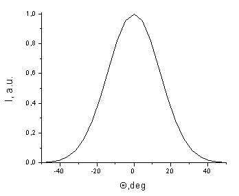
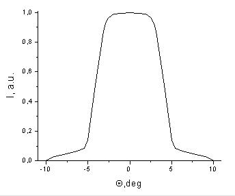
Fig. 2. Angular distribution of the diode radiance along the fast (left) and slow (right) axes, used in the calculations.
The calculations were carried out using the random ray tracing method. When calculating the intensity in the laser spot, the plane containing the spot was divided into elementary areas – squares, usually ranging in size from 1×1 μm to 20×20 μm. The power density or intensity within such an elementary section of the area was considered constant and was determined by dividing the radiation power passing through this section by its area. The text refers to this as area element averaging.
Using two lenses
This is a collimating-focusing scheme. It is standard for focusing fiber laser radiation. Since the numerical fiber aperture does not exceed 0.22-0.26, regular spherical lenses can be used for collimation. As for laser diodes, the numerical aperture of the radiation divergence along the fast axes is much greater ( 0.4-0.7, depending on the diode type), therefore, the use of spherical lenses for collimation is not practical.
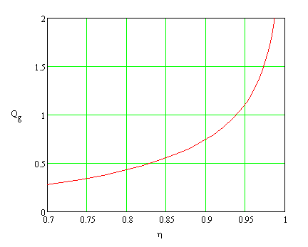
Fig. 3 shows the calculated dependence of the required aperture ratio and the numerical aperture of the collimating lens on the power fraction that this lens should intercept (and collimate). As it is seen, to intercept 90-95% of the power, lenses with an aperture ratio of 0.7-1.1 and a numerical aperture of 0.4-0.5 are required.
![]()
![]()
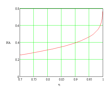
Fig. 3. Dependence of the required aperture ratio of the collimating lens (left) and the numerical aperture (right) on the power fraction that the collimating lens should intercept.
Perfect lenses
Let’s consider the focusing scheme consisting of two perfect (thin) lenses. In the geometrical optics approximation, such a scheme creates an image of the laser diode emitting end in the focal plane of the focusing lens with a magnification equal to the ratio of the focusing lens focus to the focus of the collimating one.
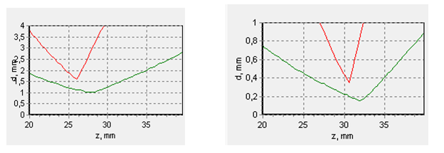
Let’s take as an example a system of two identical perfect lenses with a focus of F=50 mm. At a distance of z=50 mm from the focusing lens in the plane of the maximum focusing, the system creates an image of the emitting aperture of the laser diode as a strip of 0.4×50 μm in size. Notably, the mean power density in the spot is 30 MW/cm2 . However, at the slightest shift from the maximum focusing plane, the strip width increases rapidly (fig.4), and the power density drops rapidly.
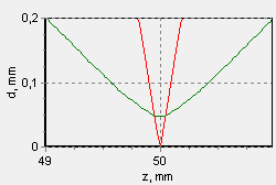
Fig.4. Transverse dimensions of the beam near the maximum focusing plane at 95% power level along the fast axis (red) and along the slow axis (green). the distance from the focusing lens is plotted along the lower axis.
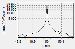
Fig. 5. The maximum local power density in the spot (kW/cm2) plotted against the distance from the focusing lens.
Thus, at a shift of only 0.07 mm, the strip turns into a square, and the maximum power density goes down to 270 kW/cm2 (fig. 6).
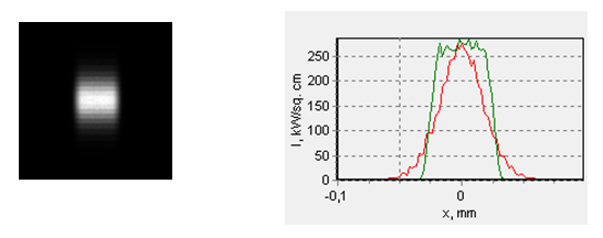
Fig. 6. The laser spot at a distance of 50.07 mm from the focusing lens (left) and their cross-section profiles along the fast (red) and the slow (green) axes. The black square side (the left picture) is 0.2 mm.
Actual spherical lenses
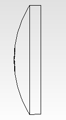
For comparison, let’s consider the situation when instead of the perfect lenses we’ll use plano-convex quartz ones with the same focus of F= 50 mm. It corresponds to the radius of the curvature of the lens spherical surface of 23 mm. Consequently, the maximum diameter of such a lens can be 46 mm, and the lens itself will look like a hemisphere. Fig. 7 shows the course of rays in such a lens in the plane parallel to the fast axes. It is well seen that some of the rays miss the lens aperture, and some have total internal reflection, and as a result, are reflected in the opposite direction. Besides, it is seen that the lens collimates only the rays hitting it close enough to its axis.
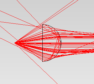
Fig. 7. The course of the rays from a laser diode placed in the focus of the quartz lens, in the plane with the fast axis. It is assumed that the lens is ideally coated, and there are no Fresnel reflections on its surfaces.
Fig. 8 shows how the beam sizes depend on the distance from the focusing lens to the surface of the maximum focusing (maximum power density).
![]()
![]()
![]()
![]()
Fig. 8. Cross dimensions of the beam along the fast (red) and slow axes (green) depending on the distance to the focusing lens at 80% (left) and 50% (right) of the power level. Note that the scales on the left and right vertical axes differ greatly.
And this is what the dependence of the maximum intensity in the spot at the same distance looks like.
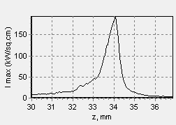
Fig. 9. Dependence of the maximum intensity in the spot (kW/cm2) on the distance to the focusing lens.
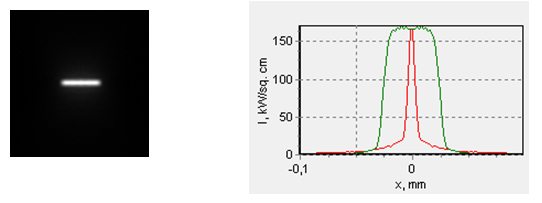
Fig. 10. The spot shape and the corresponding profiles of the intensity distribution at a distance of z=34 mm (area of the maximum local intensity in the spot) from the focusing lens. The left picture size is 0.2х0.2 mm. Only 27% of the power emitted by the diode gets into the frame (despite the ideal coating of both lenses). The red color in the right picture corresponds to the fast axis direction and the green to the slow one.
The graphs with the power density presented above are constructed by averaging the power density using the area elements of 20×20 µm. A more accurate calculation shows that the maximum power density goes to 350 kW/cm2, but this density is attained in a strip less than 1 µm wide.
Glass with a large index of refraction, the so-called heavy glass, is often used to decrease aberrations. Without resorting to exotic options, in reality we can use glass with a refraction index of about 1.8. The calculation data for a system of two identical plano-convex lenses with F=50 mm, made of glass with n=1.8 are presented in figs. 11 and 12. The lens geometrics were as follows: curvature diameter ROC= 40 mm, diameter 50 mm, thickness 10 mm.
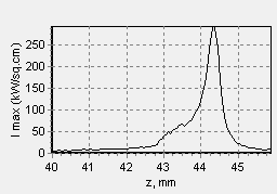
Fig. 11. Dependence of the maximum intensity in the spot on the distance from the focusing plano-convex lens with F=50 mm, and a refraction index n = 1.8.
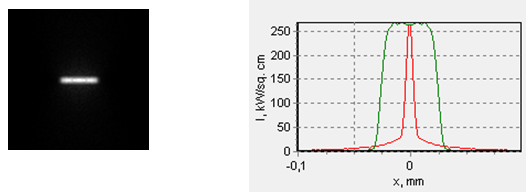
Fig. 12. The spot shape and the corresponding profiles of the intensity distribution at a distance of z=44.3 mm (area of the maximum local intensity in the spot) from the focusing lens. The left picture size is 0.2х0.2 mm. Only 37% of the power emitted by the diode gets into the frame (despite the ideal coating of both lenses). Intensity averaging is accomplished using the area of 0.01 of the frame size, i.e. 20х20 µm. The red color in the right picture corresponds to the fast axis direction and the green to the slow one.
In a narrow strip, less than 1 µm wide, the maximum power density reaches 0.7 mW/cm2, that is three times more than with quartz lenses, and three times less than with non-aberrational lenses.
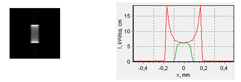
When shifting by 0.6 mm over the maximum focusing point, it is possible to obtain a more or less compact spot (by a compact spot, hereinafter, we mean a spot with approximately similar dimensions in transverse directions), but the maximum power density in such a spot will naturally be much lower. See fig. 13.
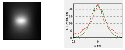
Fig. 13. The spot shape and the corresponding profiles of the intensity distribution at a distance z=44.9 mm from the focusing lens. The frame size to the left is 0.2х0.2 mm, 28% of the radiated power gets into the frame. The red graph to the right corresponds to the fast axis direction, the green one to the slow one.
Plano-convex lenses are not the best variant in terms of aberrations. For collimation and focusing it’s better to use double convex lenses with an optimal ratio of the surfaces curvature radii (usually this ratio lies in the range of 1:3 – 1:6 ). But such lenses cost more than plano-convex ones. However, calculations have shown that these lenses do not provide a significant increase in the maximum intensity in this spot as compared with the plano-convex ones.
One more way to reduce aberrations is to use specially designed sets of lenses (an object-glass) instead of single lenses. Ready-made collimators consisting of a number of lenses are found on the market. To make such collimators by ourselves would be perhaps too expensive. Sometimes, for economic reasons, they use a couple of similar plano-convex lenses as a collimating (focusing) object-glass. The calculations show that in our case this method makes it possible to increase the maximum intensity in the focused spot by approximately 15 %.
Focusing using a collimator.
2.2.1 A collimator consisting of an aspherics or of a spherical lenses set.
There are various collimators for laser diodes on the market. They may represent single aspherics or a set of spherical lenses consisting of three or more elements.
Let’s consider what we might expect from a ready-made collimator. Since the parameters of collimators are unknown, let’s assume that they don’t introduce any aberrations. Now let’s have a close look at a collimator – focusing lens scheme. In an ideal case, such a construction of two lenses creates an image of the radiating end of the laser diode at the spot of the maximum focusing. The magnifying power of this system is equal to :
where: F2 and F1 are focus distances of the collimator and the focusing lens respectively. L1 is the distance from the laser diode to the main surface of the collimator, ∆L is the distance between the lenses.
The distance from the focusing lens to the spot of the maximum focusing:
To achieve the maximum power density in the focused spot at small distances between the lenses ∆L, it is necessary to place the laser diode in the collimator focus. In which case the system magnification will equal the F2/F1 ratio, and the maximum focusing point will be in the focus of the other lens. Since the distance from the focusing lens to the focus is limited to L2 = 30-50 mm, the magnification M is limited from below by (30-50) mm/F1.
Laser diode colimators present on the market usually have a small focal range. Let’s take as an example a colimator with an 8 mm focus and NA=0.6 numerical aperture offered by OptLasers (Poland). In this case the minimum system magnification will be 3.8-6.3, and the size of the focal strip (in an ideal system without aberrations) will be about (1-3) μm х (200-300) μm, and the power density in the spot (0.8-2.0) mW/cm2.
However, at a large distance ∆L the maximum dense focusing occurs when the diode end is significantly shifted from the collimator focus. In these conditions, the beam past the collimator becomes divergent. Theoretically, by increasing the distance between the collimator and the focusing lens ∆L, we can obtain a very small spot in focus. However, this requires a focusing lens with an almost unbelikely large numeric aperture or with an aperture ratio d/f. If it is limited to an aperture ratio, say ½, then as the calculations show the magnification M from below will be limited to approximately two.
Now let’s see how the results will change if we use a actual spherical lens as a focusing one. We’ll go on assuming that the collimator does not introduce any aberrations.
So, we’ll use a quartz plano-convex lens with f=30 mm focus as a focusing lens. Here its surface curveture radius is 13.8 mm, with a diameter of 16 mm and 4 mm thick. The lens looks more or less like this:
![]()
![]()
The back-focal distance of such a lens is 27.2 mm. The calculations show that the maximum power density achieved in the focus spot is about 800 kW/cm2 if the emitting diode site is in the collimator focus. It is possible to get a compact spot by shifting from the maximum focus point approximately by 1 mm forward or backward (fig.15).
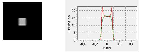

Fig. 15. “Compact” spots shapes and the corresponding intensity profiles at a distance of around 1 mm in front of the maximum focus point (top) and behind the maximum focus point (bottom). The frame side is 1х1 mm.
If we use a focusing glass lens with a reflection index of n=1.8, in this case, the maximum power intensity will be 1.1 MW MW/cm2, i.e. it differs from the entirely perfect system by a factor of less than two.
A fast-axis collimator (FAC)
The FAC reduces the corresponding radiation divergence, which makes it possible to use ordinary spherical lenses for subsequent collimation or focusing.
Previously, short-focus microlenses, made as a cylinder or a half-cylinder, were used for this purpose. A short unclad quartz fiber segment of a sufficiently large diameter could play this role.
But this kind of lens introduces significant aberrations. That is why they were replaced soon enough by aspheric cylindric lenses, i.e. by the lenses, the cylindric surface of which is modified to reduce aberrations. Today, a wide variety of lenses of this kind are available on the market.
Anyway, if ready-made aspheric cylindric lenses cannot be used for some reason or there are no high requirements for the radiation focus effectivity and precision ordinary spheric microlenses look like an alternative.
Let’s consider an ideal system consisting of a “cylindric” FAC and two “spheric” – collimating and focusing ones. We put quotes around the attributes to designate the function not the geometric shape of the component. It is assumed that an ideal system is devoid of aberrations and vignetting.
Besides, the FAC diminishes the fast axis divergence and shifts a generated image along the optic axis. For example, if the emitting laser diode end is right in the FAC focus, the image shifts to negative infinity. As a result, radiation along the fast axis focuses out of the focusing lens. In this case, it is impossible to obtain dense focusing. To improve the situation it is necessary to move the FAC as close to the laser diode as possible. The minimum distance to move the FAC to the LD end without opening its case is around 1 mm. Fig. 16 shows the results of the calculations of the maximum power density in the spot for different FAC focal lengths.
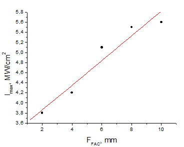
Fig. 16. Dependence of the maximum intensity in a perfectly focused spot in an ideal system a FAC + a spherical collimator (F=30 mm) + a spherical focuser (F=30 mm). The distance from the radiating LD end to the FAC is 1 mm. The intensity averaging is done using an area element of 1х1 µm. The points correspond to the calculation result, the straight line is a linear approximation. The calculation accuracy, in this case, is estimated at 1-3%.
It should be pointed out that at high values of the maximum intensity the focal depth is extremely small. Fig. 17 shows the calculated dependence of the maximum intensity in the spot on the distance to the focusing lens. As it is seen, the focal depth is within a few hundredth of a millimeter.
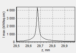
Fig. 17. Dependence of the maximum intensity in the spot on the distance from the focusing lens at FFAC = 4 mm. All the other calculation parameters are the same as for fig. 3.
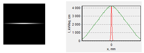
Fig. 18 shows the shape of the ultimate focusing spot and the corresponding intensity distribution along the fast and slow axes.
![]()
![]()
Fig. 18. The spot shape at the maximum intensity point (left) and intensity distribution along the fast (red) and slow (green) axes (right). The system parameters are the same as in fig. 4. The square side (left) is 0.1х0.1 mm.
To obtain a spot with approximately similar cross dimensions it is necessary to shift from the ultimate focusing intensity along the optic axis (fig.19).
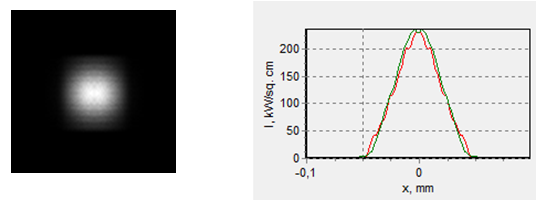
Fig. 19. The spot shape when shifted from the ultimate focusing point along the optic axis by 0.11 mm. The square size (left) is 0.2х0.2 mm.
Now let’s substitute an ideal FAC for an actualcylindric lens.
2.2.2.1 FAC in the shape of a cylinder.
Let’s take a quartz cylinder with a diameter of 1 mm for a FAC. A piece of quartz fiber can serve as a lens. Let’s see how it is possible to improve the focusing density in the case considered in 2.1.2. The calculation shows that for the maximum local power density in the focused spot the cylindric lens should be positioned right up to the laser diode end. The maximum power density will increase by one-and-a-half times compared to the case without an FAC. However, it should be noted that calculations assume that all lenses are ideally coated. In a real case, even a coated cylindric lens might introduce noticeable losses due to non-paraxial LD radiation.
As in case 2.1.2, the ultimately focused spot is at around the same distance from the focusing lens (z=32 mm) and has a shape of a significantly elongated strip along the slow axis. However, now the strip is even narrower and more elongated (around 120-130 μm).
2.2.2.2 An FAC in the form of half a cylinder
Let’s take an FAC in the form of half a cylinder with the same diameter of 1 mm. In this case, as the calculations show the optimal distance, from the power density’s point of view, between the lens and the LD end will be around 0.15 mm. In this case, the maximum power density will be twice as much as in the option without the FAC considered in 2.1.2. The spot will have a strip shape too, but its visible size will be around 8х80 μm.
2.2.3. Collimators along the fast and slow axes
It is meant that there are two collimators in the shape of two cylindric lenses – one for a fast axis, and the other for the slow one. As opposed to collimation by one aspheric lens or by a collimator assembled of spherical lenses, a pair of crossed cylindric lenses makes it possible to adjust the ratio between the divergences (or cross dimensions) along the fast and slow axes.
For example, by adjusting the FAC and SAC (Slow-Axis Collimator) focal lengths it is possible to make equal divergences along the fast and slow axes. In this case, we’ll have a spot with approximately similar sizes in two transverse directions at the focus of the focusing lens. Naturally, the waist length for the fast and slow axes will considerably differ.
As FACs, the market offers aspheric cylindric lenses with focal lengths from fractions of a millimeter to several millimeters. Lenses with a focus from a few millimeters to 10-15 mm are presented as SACs.
2.2.3.1 An ideal system
Let’s have a look at an optical system consisting of ideal lenses: two cylindric (FAC and SAC) and a spheric one (focusing lens). It is assumed that these lenses are ideally coated, do not introduce aberrations, and have big enough cross dimensions, so that radiation does not miss them. To be specific, let’s consider the following focuses: FFAC = 4 mm, FSAC = 10 mm, Ffoc = 30 mm.
Since the system is perfect, both collimators (FAC и SAC) are arranged confocally and have an emitting LD end in their mutual focus. In this case, the maximum dense focusing will be in the focus of the focusing lens. The calculations show that the maximum power density in the focal spot will be approximately 1.4 mW/cm2. If we need to obtain a “compact” spot (i.e. a spot with similar dimensions along the fast and slow axes) we’ll have to shift away from the focus by 1.4 mm (forward or backward – does not matter here). In this case, we’ll get a spot 70 х 70 m in size (at half power) with maximum intensity in the middle 33-35 kW/cm2.
Now, since we have results for an ideal system, let’s see what will change if we use actual lenses.
2.2.3.2 Aberrations effects in FAC
Let’s replace an FAC with a cylindric lens ideally coated. The other two lenses are ideal.
An FAC in the shape of a cylinder
The calculation shows that a quartz FAC in the shape of a cylinder worsens the beam SRR along the fast axis by around 50 times (at a power level of 80 %), and the beam quality gets significantly worse than the already poor one along the slow axis.
Let’s have a look at an FAC in the shape of a quartz half-cylinder with the same focus of 4 mm. Then the cylinder radius will be 1.84 mm. In this case, if we set the cylindrical lenses confocally, and set the focus at the LD end, the maximum dense focusing will be not in the focus of the focusing lens (not at a distance from the focusing lens z=30 mm) but at a distance of 22 mm. Whereby, the radiation along the fast and slow axes will focus at different places on the z-axis at a distance of 8 mm. To keep the foci along the fast and slow axes, coincided and at a distance of around the same 30 mm from the focusing lens (see fig.20, left) it is necessary to shift both lenses towards the LD. At the same time, the distance between the LD and the FAC will be 2.43 mm, and between the LD and the SAC 8.8 mm. But in this case, the spot in the area oа the maximum irradiance will look big and blurry (fig.21).
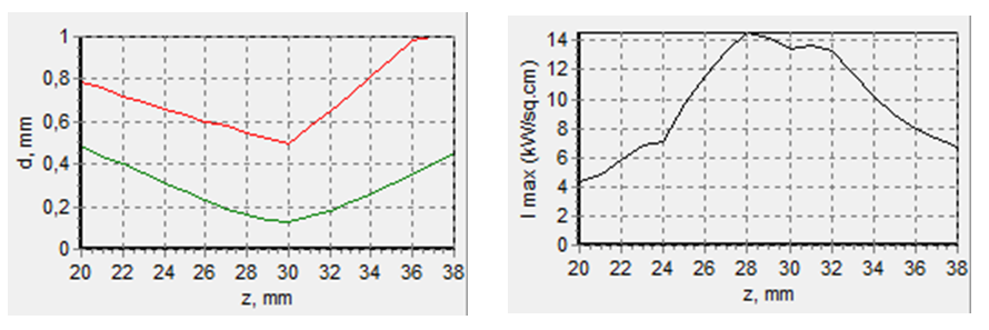
Fig. 20 Dependence of the cross dimensions of the focusing spot on the distance to the focusing lens at 80% power level (left). The red curve is a direction along the fast axis, the green along the slow. The right graph shows the dependence of the maximum power density in the spot on the same distance to the focusing lens.
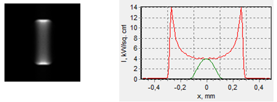
Fig. 21. The spot shape at the point of the maximum irradiance (z=28 мм) when focusing along the fast axis with a half-cylindric lens. The frame size is 1 х 1 mm.
A spot with approximately similar cross dimensions is formed if we shift from the point of the maximum focusing forward by 6.5 mm, or backward by 7 mm. The corresponding spot shapes are seen in fig. 22.
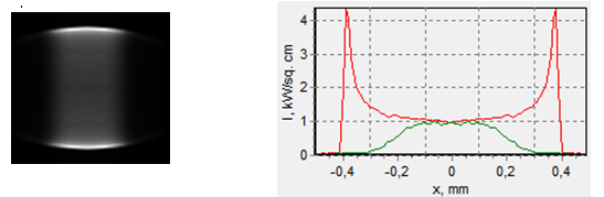
Fig. 22. The spot shape at a distance of z=21 mm from the focusing lens. The frame size is 1 х 1 mm.
![]()
![]()
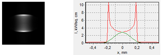
Fig. 23. The spot shape at a distance of z=34.5 mm from the focusing lens. The frame size is 1 х 1 mm.
As it is clearly seen, the quartz lens in the shape of a half-cylinder introduces significant aberrations.
If we use a half-cylinder lens made of heavy glass, the focusing spot is considerably reduced, and the maximum power density is considerably increased (fig. 24). A “compact” spot is formed in the area of the maximum irradiance. But still, the aberrations introduced by such a lens remain great.

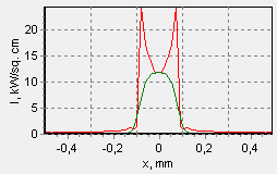
Fig. 24. The spot shape near the area of the maximum power density (irradiance) (z=31.5 мм). The frame size is 1х1 mm. The half-cylindric lens with a focus of fFAC= 4 mm (ROC= 3.2 mm) is made of glass with a refraction index of n= 1.8. The lens is set at a distance of LFAC = 2.09 mm from the LD, the slow axis collimator is at LSAC = 8.2 mm from the LD.
Up to now, a criterion for achieving the maximum spot size in the area z≈ 30 mm was used for evaluation of the FAC aberration effect. In which case, the spot size at 80% power was used. However, from the point of view of achieving the maximum power density in the spot, this criterion might not be guiding. In truth, the spot may have less than 80% of power or even considerably lower, but still high local intensity is achieved. That is why the maximum local power density level in the spot in the same distance range from the focusing lens z≈ 30 mm was used as the second optimization criterion. A 1х1 m square was taken as the minimal size of the area element for calculating the intensity in the spot.
With a quartz half-cylinder, we have the maximum irradiance of about 190 kW/cm2, the focused spot looks like a strip of 8х200 m in size (fig. 25). But this strip gets considerably less than 20% of power, the rest of which go to the weak but extended wings.
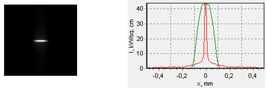
Fig. 25. The spot shape at the maximum local irradiance achieved with a quartz half-cylinder FAC in the area z≈ 30 mm. Averaging is accomplished using the area element of 10×10 m (when the area element of 10×10 m is used for averaging, the power density in the center goes up to 190 kW/cm2). The frame size is 1х1 mm. The frame gets around 63 % of power. The central square 200х200 m in size gets around 40 % of the power. The distance between the LD and the FAC is 2.74 mm, and between the LD and the SAC is 9 mm. The maximum local power density is achieved at 29.3 mm from the focusing lens.
3.1.2 The FAC as a cylinder
3.1.2.1 A quartz cylinder
According to the calculation such an FAC increases the beam parameter product (BPP) by 33 times (at the power of 80%) and the beam quality along the fast axis becomes comparable to that along the slow axis. This, it seems, allows getting a beam of approximately the same quality along the fast and slow axes, and rises chances to obtain a “compact” spot at the focus of the object glass with a large waist length. However, due to the prominent thickness of the cylindrical FAC, it is not possible to consider focusing along the slow axis independent of focusing along the fast axis. Additionally, the SAC focal length should be significantly greater than that of the FAC, otherwise they will interfere with each other. Consequently, a compact spot of a sufficiently small size is not possible to obtain at a distance of 30-50 mm from the object glass.
Let’s see what we’ll get using a quartz cylinder with the same focus F= 4 mm and a diameter of 5.04 mm. Attaining the minimum transverse dimension of the spot with the same 80% power level in the area z≈ 30 mm, a spot of this shape is generated:
![]()
![]()
![]()
![]()
Fig. 26. The spot shape at the point of minimum transverse dimensions at 80% of the power level obtained with a quartz FAC in the form of a cylinder with a 4 mm focus. The frame size is 1х1 mm; averaging of the density is accomplished using a square with a 10х10 m side. 86 % of the power gets into the square.
Striving to attain the maximum power density, we can get approximately 250 kW/cm2, the spot, at that, will have a shape of a strip 5х140 m in size; however, just like with a half-cylindric FAC, the strip has significantly less than 20 % of the power.
![]()
![]()
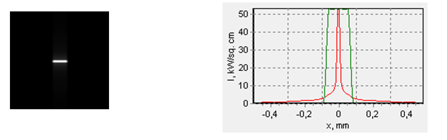
Fig. 27. The spot shape at the point of the maximum local power density obtained with a quartz FAC of a cylinder form with a focus of F= 4 mm. The square size is 1х1 mm; density averaging is accomplished, using a square with a side of 10х10 m. 73 % of the power gets into the square. Maximum power density optimization was done with a 1×1 m area element averaging, herein, the maximum density achieved was around 250 kW/cm2.
Now let’s consider application options for a quartz lens in the form of a cylinder with a diameter of 1 mm. A piece of quartz fiber could serve as such a lens. There are fibers with a core diameter of 1 mm. Probably, there are fibers with a larger diameter. Quartz-polymer fiber is the best to use, in this case the lens will be homogenous.
The focus of a quartz cylinder with a diameter of 1 mm is around 0.79 mm, and the focal segment is 0.29 mm. Consequently, such a lens can be used only when the protective glass is removed from the LD.
What can you do with such an FAC? For instance, to form a 0.15 х 0.15 mm “compact” spot, which will receive around 65 % of the radiation (fig. 28 ).
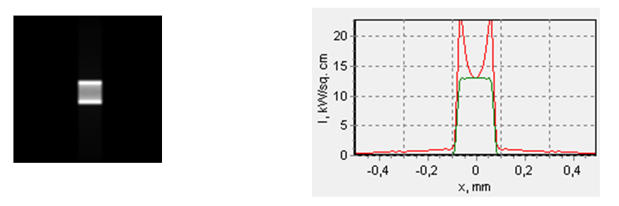
Fig. 28 A «compact» spot formed with a cylindric FAC with a 1 mm diameter. The frame size is 1х1 mm. It receives 81 % of the power, 10×10 m area element averaging. The distance from the LD end to the FAC is 0.27 mm, and from the LD to the SAC is 9.3 mm. The spot is formed at a distance of 30 mm from the focusing lens.
It is possible to get at least 100 kW/cm2, if the goal is to attain the maximum power density. The spot will look like a strip.
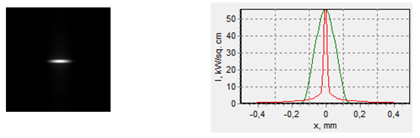
Fig. 29. The spot with a local power density of 100 kW/cm2 (with 1×1 m area element averaging), formed with a quartz cylindric FAC with a diameter of 1 mm (left). The frame size is 1х1 mm, which gets 74 % of the power. Profiles of the spot with 10×10 m area element averaging (right). LLD-FAC = 0.29 mm, LLD-FAC = 9.3 mm.
3.2 Aberrations effect in the SAC
Let’s see what effect SAC aberrations have on the focusing quality. To be more specific, we’ll use FFAC= 4 mm, FSAC= 10 mm, Ffoc= 30 mm. We assume that the FAC and the focusing lens are ideal; as an SAC we’ll take an ideal cylindric lens or an actual one. As an actual lens, we consider quartz one with ROC= 4.6 mm, 6 mm wide along the slow axis, and 2 mm thick. This lens has a focus of 10 mm. Calculations showed that within an error of a few percent, the maximum power density in the focal spot is the same for both cases and is approximately 1350 kW/cm2.
Accordingly, it is possible to use a quartz cylindric lens for collimation along the diode slow axis.
4. Conclusion
1. Collimator-focuser schemes are usually used to focus laser diodes. Single aspherics, as well as object glasses consisting of a few spherical lenses, can be used. Besides, two cylindric lenses are also used for radiation collimation: one for the fast axis and the other for the slow one. All these solutions are available on the market. Additionally, one-piece collimators capable of forming a near-circular beam are offered.
2. The use of aspheric collimating object glasses or sets of spheric lenses results either in highly elongated focal spots or in a significantly varying focal depth along the fast and slow axes.
3. The use of single spheric lenses results in considerable aberrations. The same is true for conventional cylindric lenses used for fast axes collimation. For slow axis collimation it is possible to use an ordinary cylindric lens.
4. For fast axis collimation a conventional cylindric lens is better than a half-cylinder at the same focal length. But both of them worsen the fast axis beam quality by ten folds.