Endurance laser has compatible mounting holes for M3 screws. Additional mounting kits are available upon request. The laser can be mounted to your router mount or spindle mount that you purchased from MillRight CNC and has an available M5 screw for mounting purposes. This hobby CNC machine is based off of Arduino with a CNC Shield. When purchasing a laser kit from Endurance please specify that you own a Millright CNC so that the laser control wires come with the Dupont connector necessary for connection to the CNC Shield.
Mechanical
There is never a one size fits all and sometimes you will need to just do it yourself. We can assume we are all makers/hackers and why we have our CNC / Laser machines in the first place. The following procedure is how one customer mounted their 10watt laser to the Millright CNC. Please check with Endurance laser on similar options.
This is what was used in this mounting procedure. What is this? Well it’s a curtain support bracket!
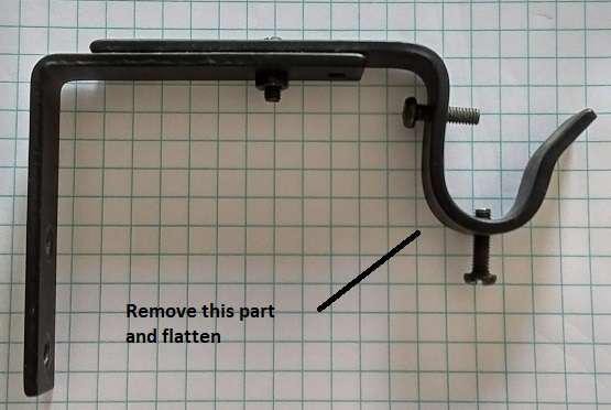
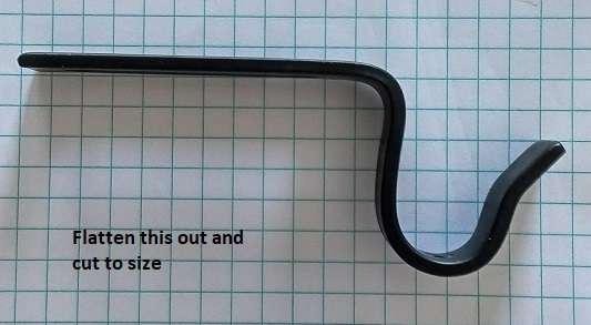
And we are left with the following:

Now let’s look at our Millright CarveKing to see how we are going to mount the Laser. Here we can see the router attached with the bracket and the bracket has a hole for our use:
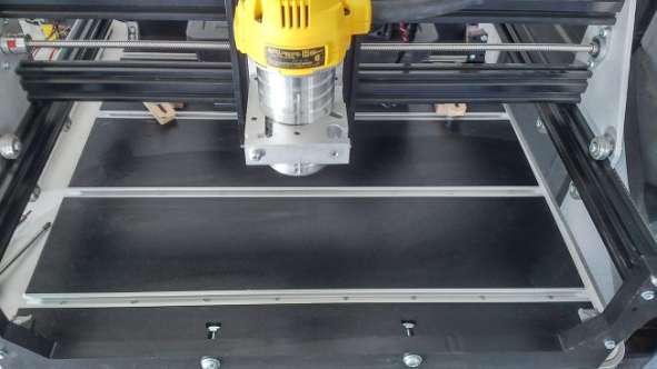
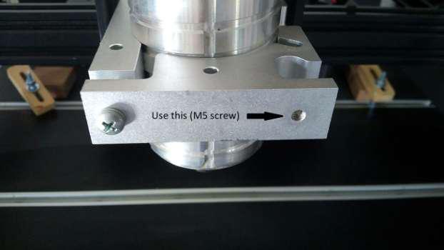
Take the bracket we made and secure it to the laser unit with an M3 screw:
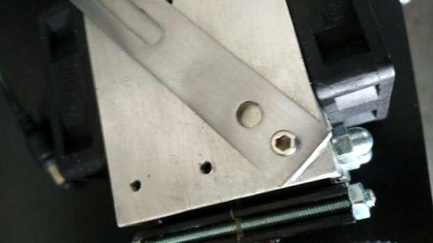
Here the bracket is purposely angled so that it is centered to the router mount. It doesn’t have to be but looks better. The reason the center screw hole is not used is because the bracked wasn’t long enough and the top fan was in the way. If you find a longer bracket then you can always use the center screw hole.
Once that is in place firmly use an M5 screw to attach the other side to the router mount:
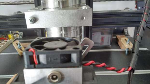
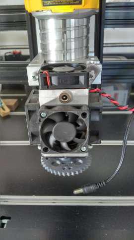
The final setup looks like this:
Electrical
Now that we have our laser mounted let’s move on to the electrical portion. Here we will be connecting the laser control wires coming from the Endurance laser (MO1 board) to the Arduino CNC Sheild.
Please note this picture of the MO1 board is only depicting the laser control wires. You will also have solder on here connects for power, laser diode and dc to dc converter.
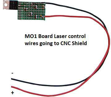
Connecting the laser to the Arduino GRBL Shield:
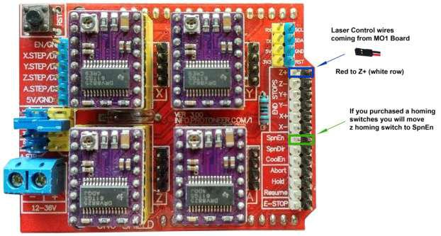
Get the wire in your laser kit that has a 2 point DuPont connector (this is the laser control signal coming out of the MO1 board). The connector will plug into the CNC shield at “Z+”. This is on the right side of the board in the section labelled “END STOPS”. This seems odd but it is correct. The red wire should be to the left and the black wire should be to the right. This is normally where the Z homing switch would plug in, but the firmware (GRBL, the control program that runs on the Arduino board) that will be used to operate the laser has reassigned some pins so it can take advantage of special pulsing features only available on this pin.
If you purchased homing switches, you will move your Z switch to the pins just below this section of the board labelled “SP En”.
Software setup:
You will need to flash the Arduino with a new firmware so you can use the laser functionality together with your router.
If you have the Carve King, get the new firmware by clicking this link:
https://sabercathost.com/9auD/Carve_King_Homing_and_No_Homing_Laser_Spindle.hex
You must load this .hex file into your control Uno board using
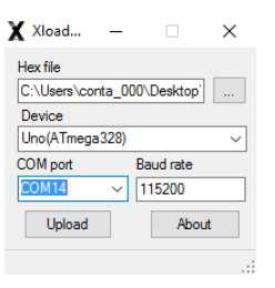
XLoader, which you can download here:
http://russemotto.com/xloader/XLoader.zip
Download and unzip XLoader. Open it, then point to the file by clicking the ellipse (…) under the window with the heading “Hex file.” The device must be “Uno.” Drop down the box for COM port, and make sure you select the COM port that the Uno is occupying. In most cases, only one COM port will show. If not, try both. Baud rate must be 115200. Click upload and wait for the confirmation.
Additional software resources:
T2Laser is a Benbox replacement for Grbl based laser and CNC systems.
It supports grey scale images, vector graphics and also has basic sketch features. You can add text to images, contour cut-out images or convert raster to vector and output it to the laser all in a single G-Code file.
Advanced algorithms for photo engraving and clipart / logos, as well as multi-pass vector cutting capabilities. Resolution, speed and power are user defined so you can maximize quality while reducing the engraving time.
http://t2graphics.weebly.com/ http://www.t2laser.org
Most laser operations will require there not to be any Z movements. The below applet will remove all Z movements from a g code file that wasn’t produced with a program designed for laser operations. You should review the output to make sure it’s ok.
LaserWeb is an open source laser program being actively developed. It’s free. You can get it here:
https://github.com/LaserWeb/LaserWeb4
A program that we like for engraving pictures is Pic Laser by PicEngrave. It can be purchased here:
http://picengrave.com/PicLaser.htm
We will provide a very brief overview here, but we are not responsible for this program in any way and we have no relationship with PicEngrave other than being their customer. Direct all technical inquiries to them.
When you first open PicLaser, it will have buttons to Select Image and Edit Image. PicLaser works with .bmp files, so you will first have to click edit image to allow you to use things such as
.jpg picture files that are probably most common on your computer. Select an image that you would like to use. Once loaded, you may need to click on the picture in the PicLaser screen so it will fit it properly. This seems to be a glitch.
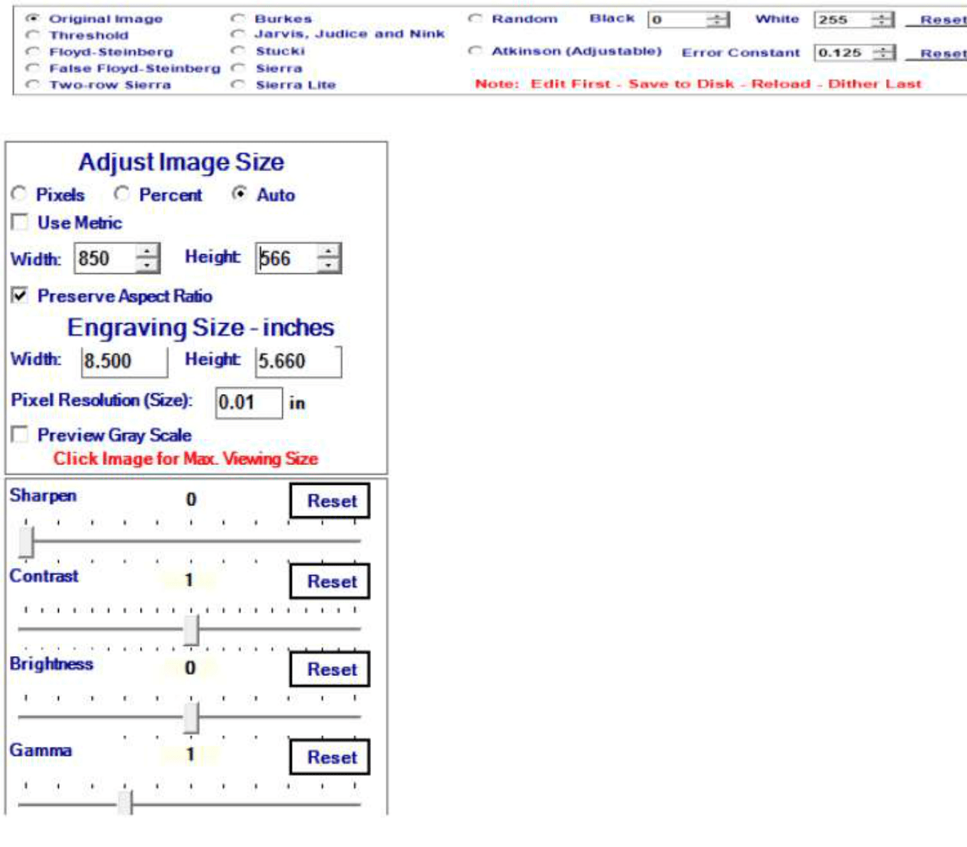
At the top you will see this bar that allows you to add different effects to the image. You can play with this to see what you like, but most often you’ll probably use Original Image. Now, on the left side is a toolbar to further manipulate the image. Click on “Auto” so you can see what size the final image will be. Leave “Preserve Aspect Ratio” checked and adjust the width and height to the size you want, keeping in mind the movement area available to you on the machine and the level of detail you want to be able to achieve. You may need to click on the image again to get it to fit in the window correctly like you did before.
You can click Preview Gray Scale to get a little more of an idea of what it will look like engraved.
Once you are satisfied with the size and other settings, click the Save button at the top left. Just rename it something easy to recognize.
Now at the top, click Return then Select Image and point to the file that you just saved. This will bring you to a screen that shows you the picture and allows you to manipulate the actual engraving settings.
Click on Change Settings. It will be at the top.
This will allow you to set up how fast you want the machine to run, the power settings, the engraving direction, the pixel size, and a number of other settings. You will need to find what works for you, but use these as a guideline. These settings have been proven to work.
The feed rate will impact how dark the image is. 1200mm/min is a good starting point, but you could go as faster if you can accept a lighter burn. You might want to change file extension to
.txt instead of .ngc. Notice that the pixel resolution will affect how large the engraved image is. 0.25mm to 0.30mm are good values. You won’t be able to see how the size of the engraved image will change until you click the Save Settings button at the bottom.
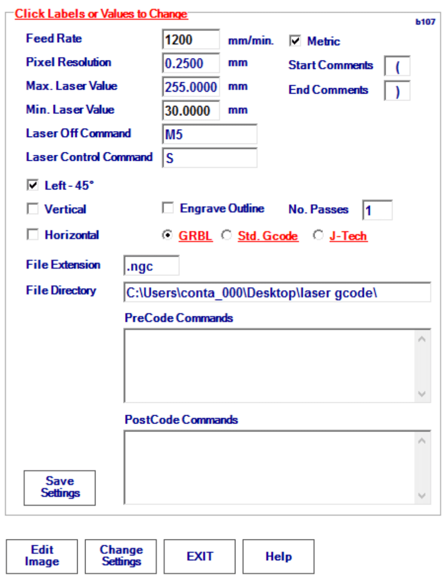
Once you have done this, click Load Image at the top left of the PicLaser program. PicLaser will advise you that it is collecting file data and ask you to wait. Then click Make G Code at the top, followed by Save G Code. It can take anywhere from several seconds to a couple of minutes to save all the G Code. The G Code file will be saved in the directory that you specified. Be advised that PicLaser does not automatically put a G90 (sets absolute positioning) at the top of the G Code file. The jogging controls on many g code programs such as Universal G Code Sender may set a G91 anytime you use the jog arrows. Before you send this file to the machine, you need to issue a G90 in the command line as PicLaser’s g code files are programmed for absolute positioning. You might also want to list a G90 in the “PreCode Commands” section of the settings window so it always places a G90 in the G Code file ahead of movement commands.
*Note: These instructions are specific to the Millright CarveKing but can also apply to the Millright M3 CNC. For the PowerRoute please check with Millright.