Explore an Endurance DPSSL
All you need to know ABOUT Nd:YAG 1064 nm impulse laser attachment.
Some abilities of Endurance DPSS laser modules.
A Diode-pumped Solid-State Laser (DPSSL)
Acronym: DPSSL = diode-pumped solid-state laser
solid-state lasers which are pumped with laser diodes
• lamp-pumped lasers, having some kind of discharge lamp as the pump source
• diode-pumped lasers, pumped with some kind of laser diodes
Types of Diode-pumped Lasers
Most diode-pumped lasers are solid-state lasers (DPSSL = DPSS lasers = diode-pumped solid-state lasers). These are either bulk lasers, using some kind of laser crystal or bulk piece of glass, or fiber lasers (although the term DPSSL is less common for fiber lasers). Both categories span a range of output powers from a few milliwatts to multiple kilowatts (→ high-power lasers).
Less common are optically pumped semiconductor lasers (particularly VECSELs = vertical external-cavity surface-emitting lasers), and there are also some relatively exotic types of diode-pumped gas lasers, e.g. alkali vapor lasers. (we do not plan to tell much about them in this post)
What Types of Laser Diodes for Diode Pumping Exist
There are different types of laser diodes that can be used for diode pumping:
• Low-power lasers (up to roughly 200 mW) can be pumped with small edge-emitting laser diodes. These exhibit a diffraction-limited beam quality and make it fairly easy to achieve the same for the solid-state laser.
• Broad area laser diodes typically generate several watts and are suitable for pumping solid-state lasers with output powers up to a few watts. Their beam quality is substantially asymmetric, but normally still sufficient for achieving a diffraction-limited laser output without using complicated optics.
• High-power diode bars emit dozens of watts (up to 100 watts), allowing for higher output powers, particularly when several bars are combined. Their beam quality is strongly asymmetric and fairly poor so that their radiance (brightness) is much lower than that of lower-power diodes. Various types of beam shapers are used to symmetrize the beam quality. This makes it easier either to pump a bulk laser or to couple the light into a fiber.
• For the highest powers, diode stacks are often used. These have a still worse beam quality and lower brightness but can provide multiple kilowatts.
In most cases, the pump diodes are operated continuously. This applies to all continuous-wave and mode-locked lasers, and also to many Q-switched lasers. However, quasi-continuous-wave operation with higher peak power for limited time intervals (e.g. 100 μs) is sometimes used for Q-switched lasers with high pulse energy and low pulse repetition rate.
Depending on the type of laser diode, different kinds of pump optics are used. It is also possible to use fiber-coupled diode lasers, which make it possible to separate the actual laser head from another package containing the pump diodes so that the laser head can become very compact.
Advantages of Diode Pumping
The main advantages of diode pumping are:
• The high electrical-to-optical efficiency of the pump source (of the order of 50%) leads to a high overall power efficiency (→ wall-plug efficiency) of the laser. As a consequence, small power supplies are needed, and both the electricity consumption and the cooling demands are drastically reduced, compared with those for lamp-pumped lasers.
• The narrow optical bandwidth of diode lasers makes it possible to pump directly certain transitions of laser-active ions without losing power in other spectral regions. It thus also contributes to high efficiency.
• Although the beam quality of high-power diode lasers is not perfect, it often allows for end pumping of lasers with a very good overlap of laser mode and pump region, leading to high beam quality and power efficiency. In the domain of slab lasers, it allows edge pumping instead of face pumping, which brings important advantages.
• Diode-pumped low-power lasers can be pumped with diffraction-limited laser diodes. This allows the construction of very low-power lasers with reasonable power efficiency, i.e., with a very small electrical pump power, as is important for battery-powered devices.
• The lifetime of laser diodes is long compared with that of discharge lamps: typically many thousands of hours, often even well above 10 000 hours. However, various factors can lead to drastically reduced lifetimes. The exchange of laser diodes is also much more costly than that of discharge lamps.
• The compactness of the pump source, the power supply, and the cooling arrangement makes the whole laser system much smaller and easier to use.
• Diode pumping makes it possible to use a very wide range of solid-state gain media for different wavelength regions, including e.g. upconversion lasers. For many solid-state gain media, the lower brightness of discharge lamps would not be sufficient.
• The low-intensity noise of laser diodes leads to the low noise of the diode-pumped laser.
Achievements
The benefits of diode pumping have to lead to amazing achievements. Some examples are:
• There are miniature solid-state lasers with excellent efficiency, beam quality, spectral purity, and stability. Some of those may even be battery-powered.
• Diode-pumped high-power solid-state lasers can deliver kilowatt output powers with fairly high beam quality. This applies particularly to thin-disk lasers, but also to high-power fiber lasers and amplifiers.
• Diode pumping is also essential for a large variety of mode-locked lasers, generating e.g. up to 80 W of average output power in sub-picosecond pulses, or picosecond pulses for telecom applications with a pulse repetition rate up to 50 GHz.
Limitations
In the early years of diode pumping, the output powers achievable were very limited – smaller than those of lamp-pumped lasers. In the meantime, however, high-power diode bars and diode stacks have become very powerful, and the highest output powers are now usually achieved with diode pumping.
The main disadvantage of diode pumping (as compared with lamp pumping) is the significantly higher cost per watt of pump power. This is severe for high powers. For this reason, lamp pumping is still used in cases where high powers are needed, particularly when the power is used only for short times. For example, lamp-pumped Q-switched Nd:YAG lasers are still widely used for laser marking, and will not soon be replaced with diode-pumped lasers.
Laser diodes are electrically less robust than discharge lamps. They may e.g. be quickly destroyed by excessive drive currents, or by electrostatic discharges. In conjunction with properly-designed electronics, however, this should not happen. Problems can also arise from optical feedback.
Applications
Diode-pumped solid-state lasers have a very wide range of applications. Indeed, they are used in all of the areas mentioned in the article on laser applications.
Diode-pumped solid-state lasers (DPSSLs) are solid-state lasers made by pumping a solid gain medium, for example, a ruby or a neodymium-doped YAG crystal, with a laser diode.
DPSSLs have advantages in compactness and efficiency over other types, and high power DPSSLs have replaced ion lasers and flashlamp-pumped lasers in many scientific applications, and are now appearing commonly in green and other color laser pointers.
Coupling
The wavelength of laser diodes is tuned by means of temperature to produce an optimal compromise between the absorption coefficient in the crystal and energy efficiency (lowest possible pump photon energy). As waste energy is limited by the thermal lens this means higher power densities compared to high-intensity discharge lamps.
High power lasers use a single crystal, but many laser diodes are arranged in strips (multiple diodes next to each other in one substrate) or stacks (stacks of substrates). This diode grid can be imaged onto the crystal by means of a lens. Higher brightness (leading to better beam profile and longer diode lifetimes) is achieved by optically removing the dark areas between the diodes, which are needed for cooling and delivering the current.
This is done in two steps:
1. The “fast axis” is collimated with an aligned grating of cylindrical micro-lenses.
2. The partially collimated beams are then imaged at reduced size into the crystal. The crystal can be pumped longitudinally from both end faces or transversely from three or more sides.
The beams from multiple diodes can also be combined by coupling each diode into an optical fiber, which is placed precisely over the diode (but behind the micro-lens). At the other end of the fiber bundle, the fibers are fused together to form a uniform, gap-less, round profile on the crystal. This also permits the use of a remote power supply.
The end face of the diode along the fast axis can be imaged onto a strip of 1 µm height. But the end face along the slow axis can be imaged onto a smaller area than 100 µm. This is due to the small divergence (hence the name: ‘slow axis’) which is given by the ratio of depth to width. Using the above numbers the fast axis could be imaged onto a 5 µm wide spot.
So to get a beam which is an equal divergence in both axis, the end faces of a bar composed of 5 laser diodes, can be imaged by means of 4 (a cylindrical) cylinder lenses onto an image plane with 5 spots each with a size of 5 mm x 1 mm. This large size is needed for low divergence beams. Low divergence allows paraxial optics, which is cheaper, and which is used to not only generate a spot but a long beam waist inside the laser crystal (length = 50 mm), which is to be pumped through its end faces.
Also in the paraxial case, it is much easier to use gold or copper mirrors or glass prisms to stack the spots on top of each other and get a 5 x 5 mm beam profile. A second pair of (spherical) lenses image this square beam profile inside the laser crystal.
In conclusion, a volume of 0.001 mm³ active volume in the laser diode is able to saturate 1250 mm³ in a Nd:YVO4 crystal.
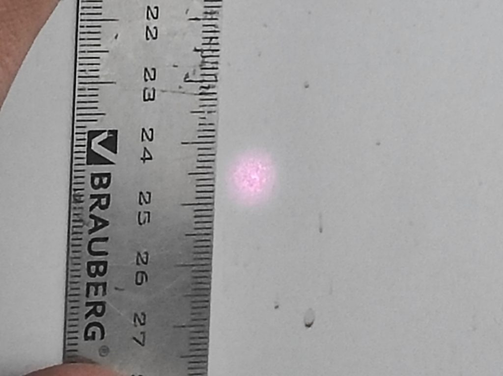
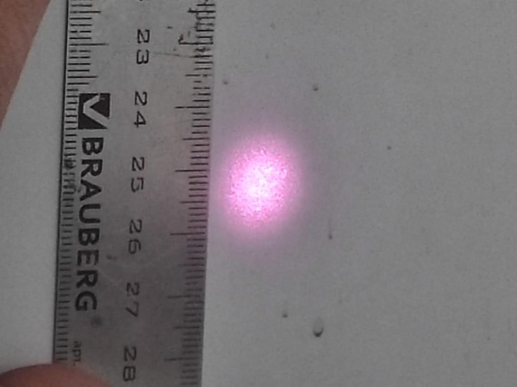
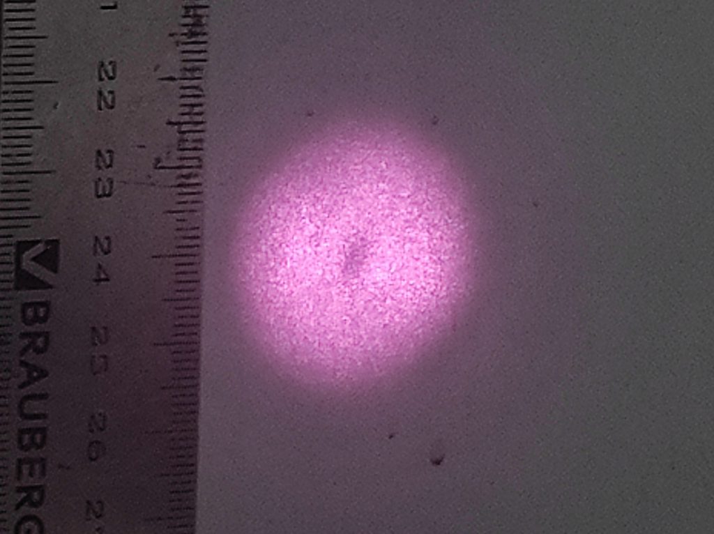
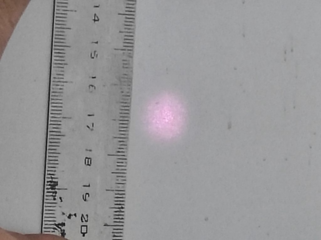
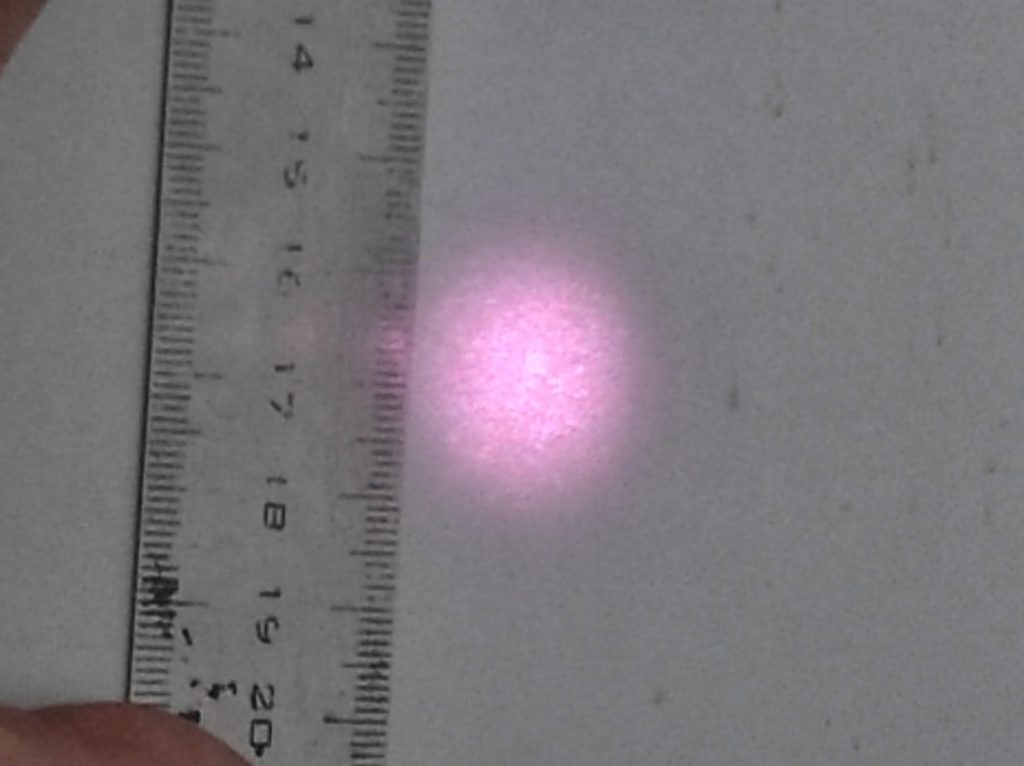
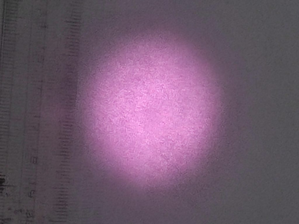
Laser beam quality: 10 watt DPSS Nd:YAG initial laser beam spot
2,7 meter range
4,5 meter range
Common DPSSL processes
Neodymium ions in various types of ionic crystals, and also in glasses, act as a laser gain medium, typically emitting 1,064 nm light from a particular atomic transition in the neodymium ion, after being “pumped” into excitation from an external source. Selection of 946 nm transition light is possible, as well
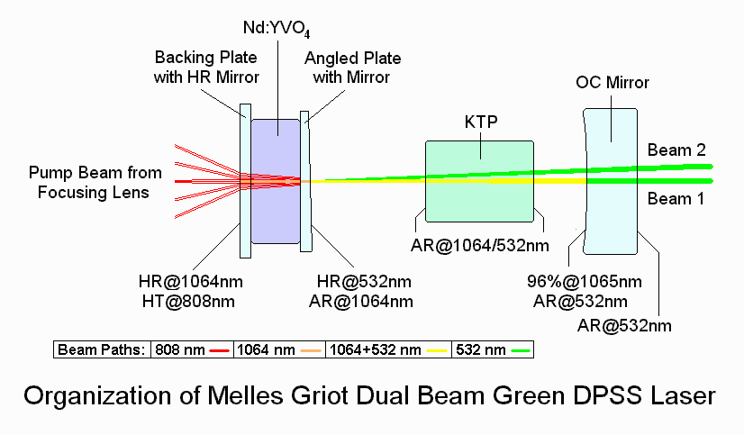
The most common DPSSL in use is the 532 nm wavelength green laser pointer. A powerful (>200 mW) 808 nm wavelength infrared GaAlAs laser diode pumps a neodymium-doped yttrium aluminum garnet (Nd:YAG) or a neodymium-doped yttrium orthovanadate (Nd:YVO4) crystal which produces 1064 nm wavelength light from the main spectral transition of neodymium ion. This light is then frequency doubled using a nonlinear optical process in a KTP crystal, producing 532 nm light. Green DPSSLs are usually around 20% efficient, although some lasers can reach up to 35% efficiency. In other words, a green DPSSL using a 2.5 W pump diode would be expected to output around 500-900 mW of 532 nm light.
In optimal conditions, Nd:YVO4 has a conversion efficiency of 60%,[1] while KTP has a conversion efficiency of 80%.[2] In other words, a green DPSSL can theoretically have an overall efficiency of 48%.
In the realm of very high output powers, the KTP crystal becomes susceptible to optical damage. Thus, high-power DPSSLs generally have a larger beam diameter, as the 1064 nm laser is expanded before it reaches the KTP crystal, reducing the irradiance from the infrared light. In order to maintain a lower beam diameter, a crystal with a higher damage threshold, such as LBO, is used instead.
Blue DPSSLs use a nearly identical process, except that the 808 nm light is being converted by an Nd:YAG crystal to 946 nm light (selecting this non-principal spectral line of neodymium in the same Nd-doped crystals), which is then frequency-doubled to 473 nm by a beta barium borate (BBO) or lithium triborate (LBO) crystal. Because of the lower gain for the materials, blue lasers are relatively weak and are only around 3-5% efficient. In the late 2000s, it was discovered that bismuth triborate (BiBO) crystals were more efficient than BBO and LBO and do not have the disadvantage of being hygroscopic, which degrades the crystal if it is exposed to moisture.
Yellow DPSSLs use an even more complicated process: An 808 nm pump diode is used to generate 1,064 nm and 1,342 nm light, which are summed in parallel to become 593.5 nm. Due to their complexity, most yellow DPSSLs are only around 1% efficient, and usually more expensive per unit of power.
Another method is to generate 1,064 and 1,319 nm light, which are summed to 589 nm.
This process is more efficient, with about 3% of the pump diode’s power being converted to yellow light.
Comparison to diode lasers
DPSSLs and diode lasers are two of the most common types of solid-state lasers. However, both types have their advantages and disadvantages.
DPSSLs generally have a higher beam quality and can reach very high powers while maintaining relatively good beam quality. Because the crystal pumped by the diode acts as its own laser, the quality of the output beam is independent of that of the input beam. In comparison, diode lasers can only reach a few hundred milliwatts unless they operate in multiple transverse modes. Such multi-mode lasers have a larger beam diameter and a greater divergence, which often makes them less desirable. In fact, the single-mode operation is essential in some applications, such as optical drives.
On the other hand, diode lasers are cheaper and more energy-efficient. As DPSSL crystals are not 100% efficient, some power is lost when the frequency is converted. DPSSLs are also more sensitive to temperature and can only operate optimally within a small range. Otherwise, the laser would suffer from stability issues, such as hopping between modes and large fluctuations in the output power. DPSSLs also require a more complex construction.
Diode lasers can also be precisely modulated with a greater frequency than DPSSLs.
Neodymium-doped solid-state lasers continue to be the laser source of choice for industrial applications. Direct pumping of the upper Nd laser level at 885-nm (rather than at the more traditional broad 808-nm band) offers the potential of improved performance through a reduction in the lasing quantum defect, thereby improving system efficiency, reducing cooling requirements, and enabling further TEM00 power scaling. Because of the narrow 885-nm absorption feature in Nd:YAG, certain systems may benefit from the use of wavelength-locked diode pump sources, which serve to narrow and stabilize the pump emission spectrum to keep it closely aligned to this absorption feature. To date, high power diode laser locking schemes such as internally distributed feedback Bragg gratings and externally aligned volume holographic grating optics, VHG’s, have not been widely implemented due to the increased cost and assumed performance penalty of the technology. However, recent advancements in the manufacture of stabilized diode pump sources that utilize external wavelength locking now offer improved spectral properties with little-to-no impact on power and efficiency. The benefits of this approach include improvements in laser efficiency, spectral linewidth, and pumping efficiency.
Diode-pumped solid-state (DPSS) lasers are solid-state lasers made by pumping a solid gain medium, for example, a ruby or a neodymium-doped yttrium aluminum garnet (YAG) crystal, with a laser diode. DPSS lasers have advantages in compactness and efficiency over other types, and high power DPSS lasers have replaced ion lasers and flashlamp-pumped lasers in many scientific applications, and are now appearing commonly in green and other color laser pointers.
Diode laser pump sources allow operation at higher efficiency (10%) and longer life (20.000 hours).
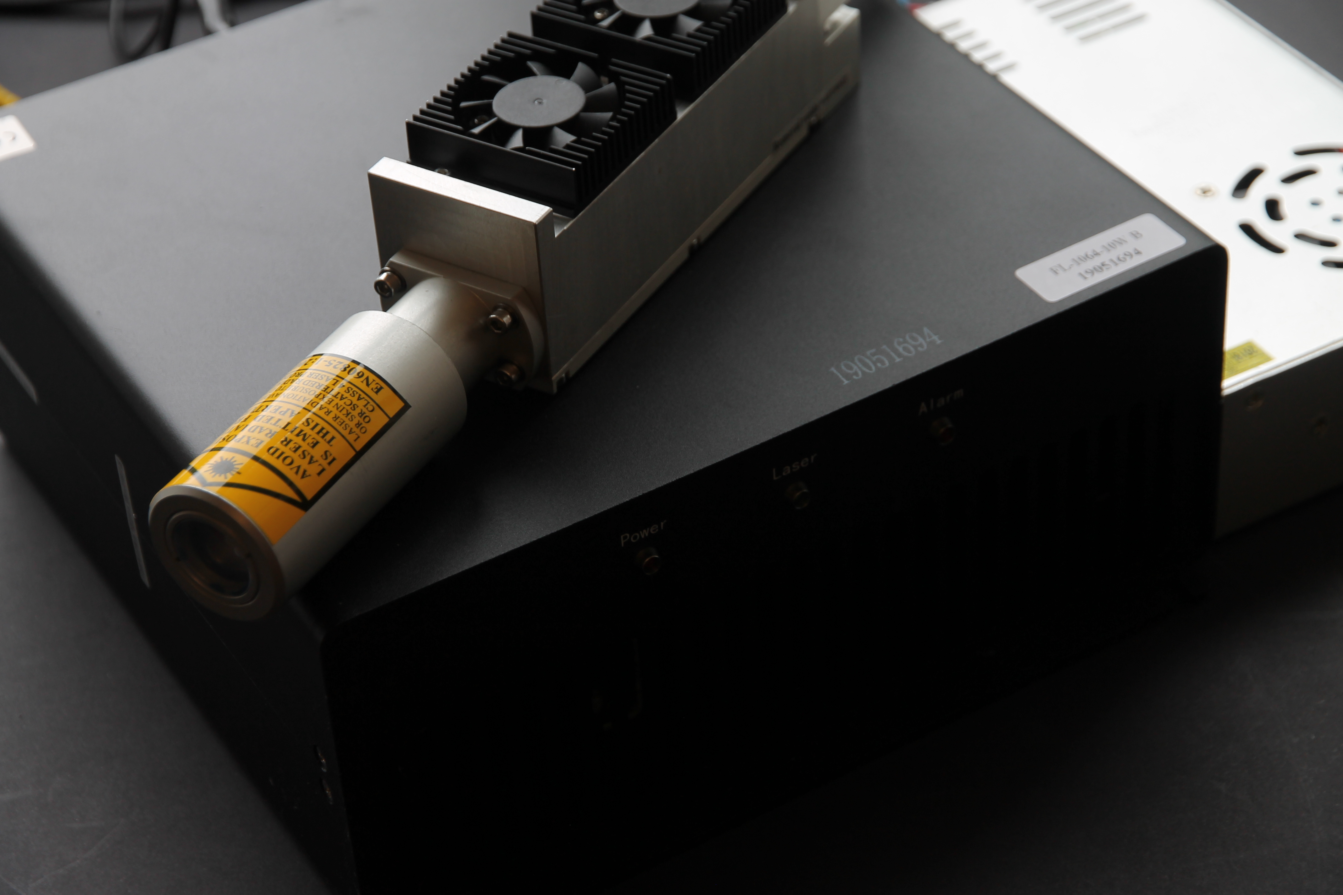
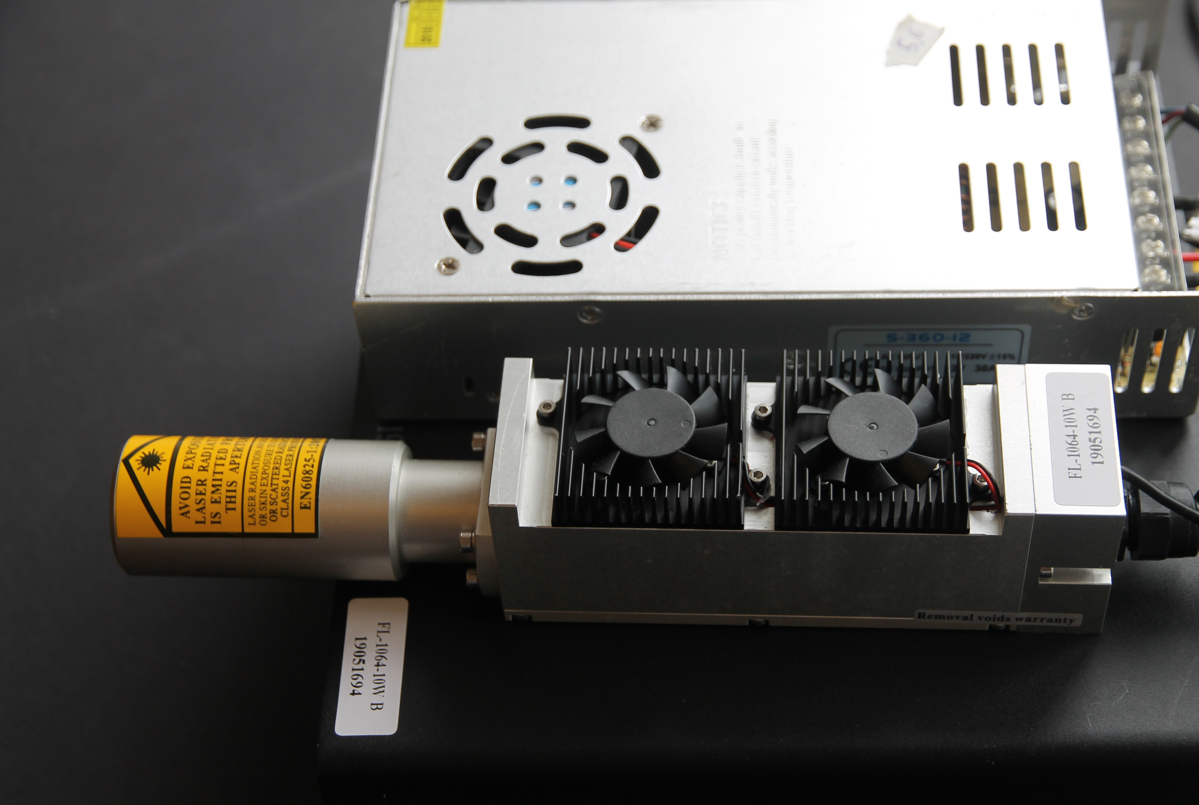
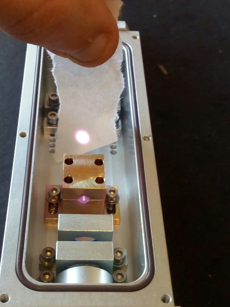
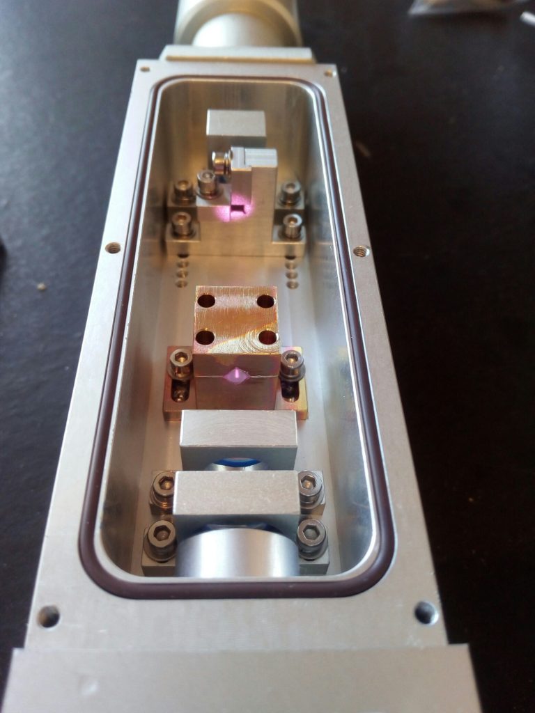
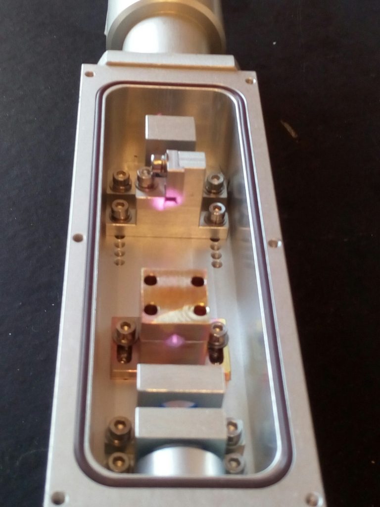
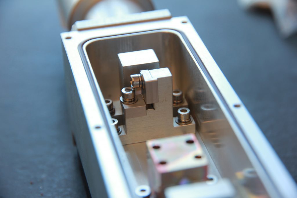
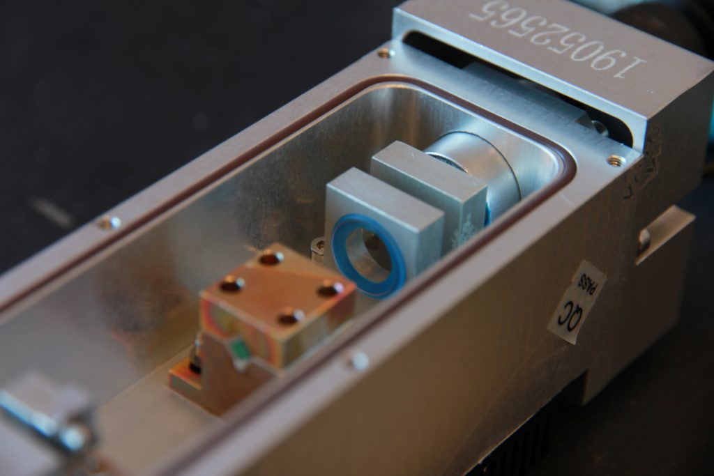
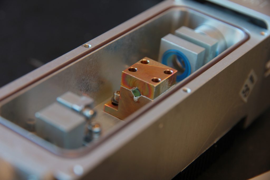
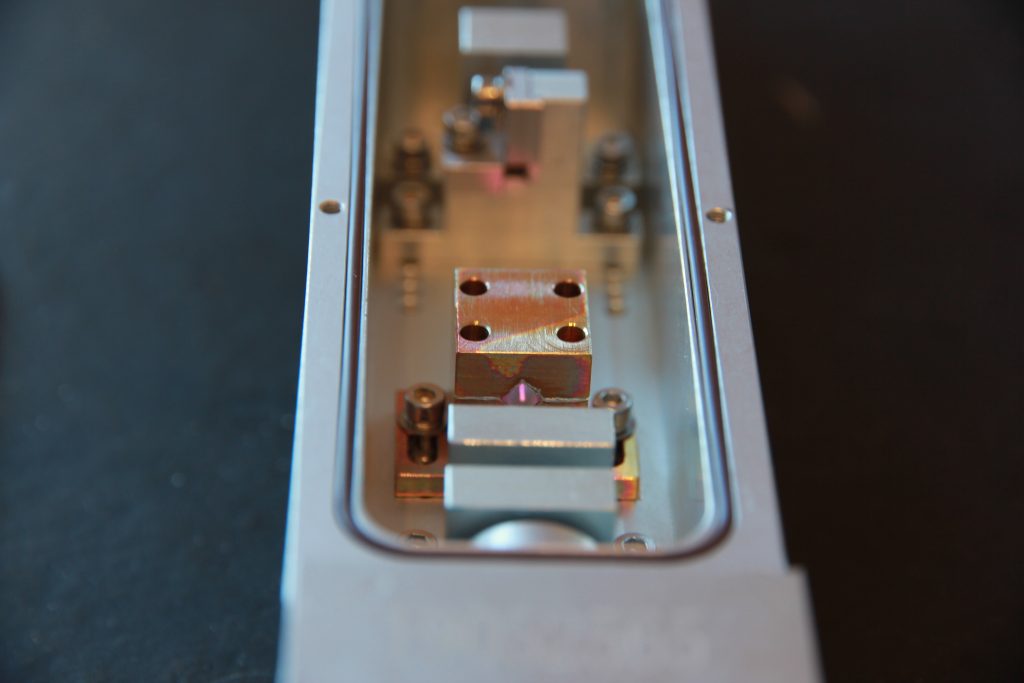
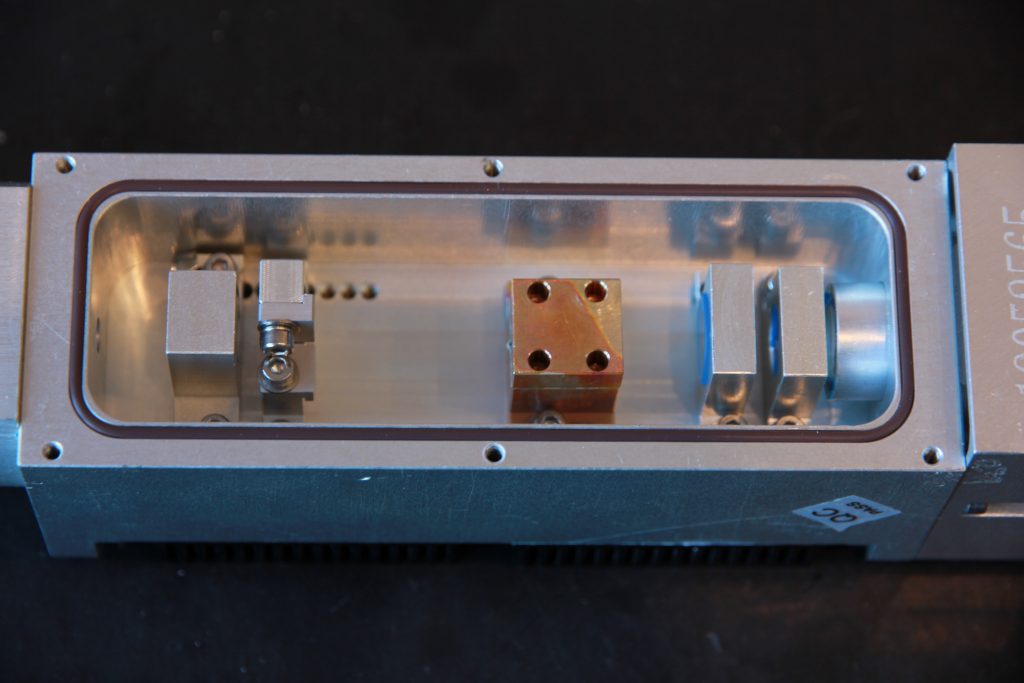
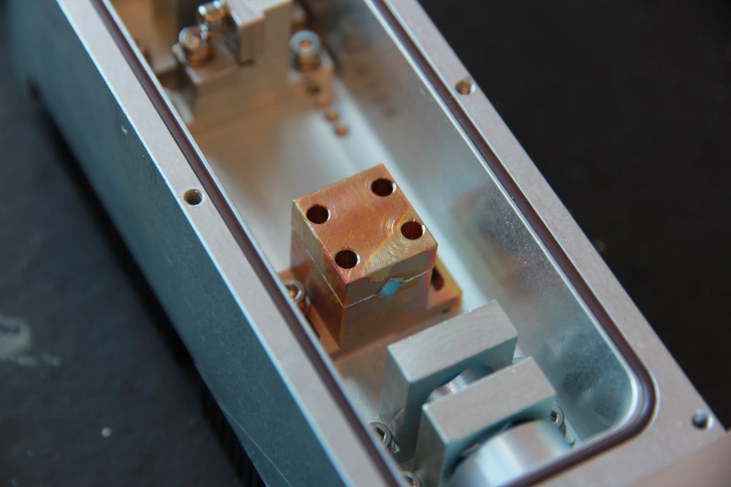
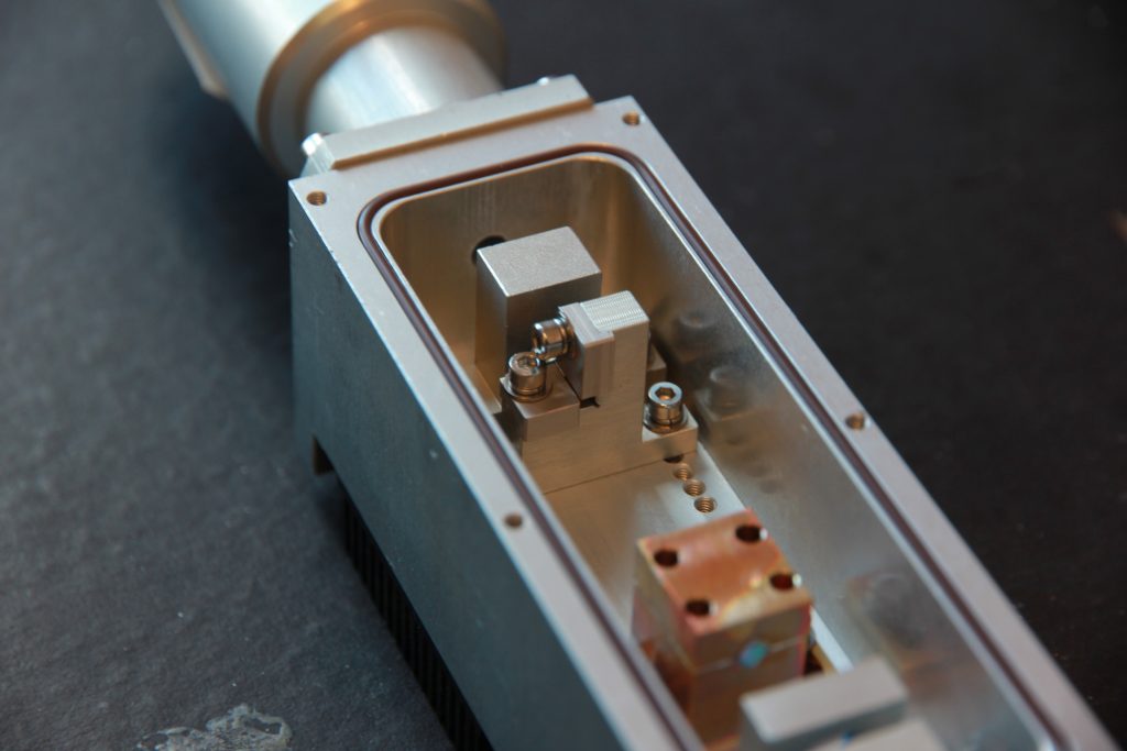
Inside the laser head (Nd:YAG) 10 watt 1064 nm
Pumping process
Advantages of diode pumping Summarize some of the typical characteristics of DPSS lasers:
1. Optical efficiency: DPSS lasers are highly efficient because of the direct excitation of the pump beam into the useful absorption band of the lasing ion. Direct excitation minimizes the unwanted losses in the lasing crystal with optical to optical efficiency of up to 70%. Selecting the composition of the host material enables laser diodes to be constructed with wavelengths between 600 nm and approximately 30 µm in the infrared. Over much of this region, the output power and lifetime of laser diodes is remarkably poor. Only in wavelength regions where strong commercial or military interest is present have sufficient resources been deployed to develop an efficient and long-lived device. Notable examples of this process have occurred at 1.5 µm and 1.3 µm, which are important telecommunications wavelengths, and near 800 nm which is important for communications, entertainment, and medical applications. Only in the vicinity of 800 nm have high-powered devices been built. The driving force has been military applications including pumping Nd-doped solid-state lasers
2. Wavelength: The wavelength at which laser diodes operate is dictated by the size of the bandgap since the light arises from the recombination of electrons and holes in a PN junction. The bandgap may be tuned in size by two main processes: (i) Altering the composition of the host material. (ii) Changing the temperature of the host material. Other physical effects such as the application of pressure may also change the bandgap but they tend to produce too small an effect to be useful [7]. The output wavelength of diode lasers varies from diode to diode because of small differences in fabrication and the wavelength changes with temperature. The variation in output wavelength leads to increased cost because only diode lasers in a small wavelength range are usable. The change in wavelength resulting from temperature variation requires that the diodes must be temperature controlled.
3. Operational lifetime: The operational lifetime of laser diodes or arrays is much larger than that of conventional arc or filament lamps. A typical laser diode array can operate without significant degradation for more than 10.000 hours, but usually up to 3×10^4 hours, while a cw lamp must be replaced after 200-400 hours of operation (or 10^7 shots in the case of pulsed pumping). The performance of a diode laser degrades exponentially with time. Initially, the failure rate is low, but it increases exponentially with the operating time. Failure mechanisms of laser diodes are divided into two main classes:
1. User induced damage (such as mechanical, thermal or electrical shock or electrostatic discharge).
2. Intrinsic damage, which results from three main sources:
(i) degradation of laser mirrors or facets because of high current densities or current spikes. This will increase internal losses and lead to catastrophic failure.
(ii) damage resulting from crystal defects within the active region, which will lead to an increase in absorption losses within the laser diode. Such defects are common in AlGaAs laser diodes because of the oxidation and migration of the aluminum. At present efficient aluminum-free laser diodes replace the aluminum-containing lasers.
(iii) resistive losses and heating because of increases in the resistance of electrical contacts to the laser
4. Temperature: Since the diode laser is a narrow bandwidth pumping source, it pumps only the useful absorption bands relevant to laser action, reducing the thermal load in the crystal. This thermal load results from the quantum gap between the pump and the leasing photons. Thermal effects such as thermal lensing, thermally induced birefringence, and thermal damage to the lasing to the crystal are reduced significantly. Fine-tuning the temperature of the laser diode causes a change in wavelength. For GaAlAs devices the wavelength tunes at an approximate rate of +0.25 nm ºC-1 mainly due to the change in bandgap with temperature. This feature is used to tune the laser diode into coincidence with the absorption bands of rare-earth ions. Normally the lasers will be cooled down since this gives a longer lifetime for the laser diode. It is usual to specify the room temperature wavelength of the laser diode some 5 nm longer than the rare earth absorption feature that will be pumped. Simple Peltier coolers can provide a temperature change of about 40 ºC corresponding to a wavelength shift of 10 nm. The Nd:YAG absorption linewidth is ~2 nm so the diode temperature has to be set to better than ±4 ºC, which is not too demanding in the laboratory. The influence of temperature on the wavelength of the laser diode causes problems of packaging the DPSS laser. Pulsed laser diodes suffer from a transient thermal wavelength shift. Since the current is pulsed through the laser diode, the temperature is never in equilibrium and a transient wavelength shift occurs. The wavelength increases during the optical pulse. Measurements of this effect have revealed shifts of ~5 nm. Shifts of this magnitude are larger than the absorption linewidth of many solid-state laser materials. Account has to be taken of this effect when predicting the efficiency of pulsed DPSS lasers. The diode lasers are normally cooled by a thermoelectric cooler for low power systems, and by liquid cooling for high powers. Cooling can stabilize the diode laser frequency
5. Beam quality: Although the beam quality of a laser diode or diode array is not good, the use of coupling optics makes it possible to obtain a good TEM00 beam mode from a DPSS laser. The coupling optics circularize the output beam emanating from the laser diode array or bar, and then couple the beam into the solid-state laser crystal either by direct coupling or an optical fiber [12]. The cylindrical fast axis collimating lens can reduce the beam divergence of diode laser stacks to a value of lens than 10 mrad. The solid-state laser can be pumped longitudinally or transversely. This subject is technologically well established and will be discussed in the next section. The laser crystal host can be in the form of a crystal, waveguide or optical fiber [7]. Since the absorption length of the diode laser beam focused inside the solid-state laser crystal is short, the pump mode volume is smaller than the laser cavity mode volume and one expects a good spatial beam quality. The laser cavity itself is short and therefore the output power of the DPSS laser is a single longitudinal mode. The best transverse mode quality is obtained from single stripe devices. The low ellipticity of a source with dimensions of 3×1 µm ensures that the output power may be efficiently coupled into an optical fiber or into solid-state laser materials. Single laser diodes may provide up to 150 mW in a single transverse mode.
To date, the most extensively used pumping geometry is longitudinal pumping. The output from the diode laser is collimated and beam-shaped to achieve a circular profile before being focused down to form a pump spot on the laser rod. This technique allows good matching between the lasing spot size of the solid-state laser cavity and the pump spot size in the gain medium. This spatial overlap between pump and lasing modes, known as mode matching, is critical to the efficiency of the diode pumping process. Frequently, DPSS lasers are pumped by laser diode arrays in order to achieve high output powers. As has been noted, the simplest way to increase the output power from a single laser diode is to increase the width of the emitting region either by fabricating a number of laser diode stripes in close proximity so that there is a series of emitting regions or by enlarging the width of the electrically pumped region. The output of arrays lies in the region of 200 mW to 3 W cw output at present. True arrays of laser diode stripes tend to be partially coherent and may exhibit the two-lobe structure in the far-field characteristic of the phase changes due to the evanescent coupling between adjacent stripes. This feature appears less obvious as the output power and number of stripes increase due to reduced coherence across the array. The broad stripe arrays are multi-transverse mode devices and the beam quality depends on how hard they are driven [7]. Applications of high power fiber delivery from diode lasers include pumping either bulk or fiber lasers, machining and marking, soldering, and power transmitting. High power fiber-coupled diode laser sources could lead to the creation of compact high power diode-pumped lasers. Similar systems that have been demonstrated either have relatively low power because they were limited to only one or two sources focused into a fiber, or because they consist of a fiber bundle in which one or two sources were focused into a fiber and then many fibers were brought together to form the pump source. A single fiber to carry all the power, as opposed to a fiber bundle, is desirable because it is less bulky and it maintains a greater degree of pump beam brightness, which allows improved performance from diode-pumped lasers.
Learn more >>>
To thoroughly characterize a Q-switched laser system, certain beam parameters must be known. Several of these parameters can be easily measured and used to calculate the rest. Measured Parameters: Average Power Repetition Rate Pulse Duration Calculated Parameters: Energy per Pulse Peak Power Average power is measured using a direct reading power meter. Since average power is measured while the laser is Q-switching (pulsing), the repetition rate at which the measurement was taken should be noted. Repetition rate is measured by observing the output pulse train on an oscilloscope and determining the number of pulses per second. Pulse duration is determined by viewing the laser output on an oscilloscope and applying the full-width-half-maximum (FWHM) criteria
CALCULATIONS: Energy per pulse: Energy per pulse is determined by dividing the average power by the repetition rate.
The resultant quantity is the energy, in Joules, contained in EACH laser pulse.
Where: E = Energy in Joules PAv = Average power in Watts RRate = Repetition rate in pulses per Second.
Peak Power per Pulse: Peak Power per pulse is determined by dividing the energy per pulse by the pulse duration.
Where pk : P = Peak power in Watts E = Energy per pulse in Joules Dpulse = Pulse duration at the full-width-half-maximum points.
Example 1: A laser is operated at a 5 kHz repetition rate, at an average power of 2 Watts. Using this information, we can calculate the energy per pulse as follows: E = 2/5000 = .0004 Joules = 0.4 x 10 Joules (0.4 millijoules) per pulse. -3
Example 2: In the previous example we determined that the 2 Watt average power laser operating at 5 kHz has a pulse energy output of 0.4 millijoules. In addition, assume that we measured the pulse duration to be 150 nanoseconds (10 seconds). With this information, the peak pulse power -9 can be calculated as follows: Ppk = (.4 x 10 )/(150 x 10 ) = 2.667 x 10 Watts (2.67 kilowatts).
Example 3: 10 watt laser with 27 000 Hz (27 kHz) and duration pulse of 7 ns with have 52.9 kW peak power
Example 4: 20 watt laser with 25 000 Hz (25 kHz) and duration pulse of 100 ns with have 8 kW peak power
Example 5: 50 watt laser with 50 000 Hz (50 kHz) and duration pulse of 120 ns with have 8.6 kW peak power
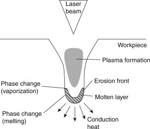
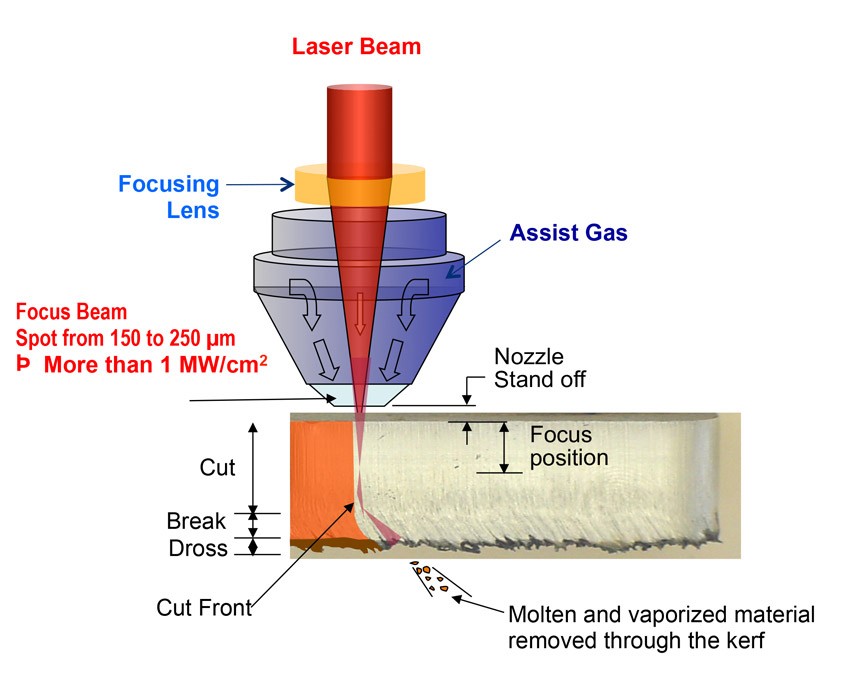
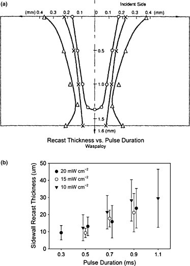
How does the peak power affect the depth and accuracy of a laser engraving and cutting
Metal cutting on a 3D printer (Anet A8)
What you can do with a 1064 nm DPSS impulse Nd:YAG laser module
Precision Optics
CNI design and manufacture of precision optical components and assemblies. As described in the customer solutions, we have strong capability to design and fabricate custom made optics with variously optical materials.
Coated Laser Crystal
CNI is capable of supplying a large quantity of laser crystals with high damage coatings to meet the tough requirement from both the OEM and R&D customers.
Output Coupler
An output coupler (OC) is a partially reflective mirror used in lasers to extract a portion of the laser beam from the optical resonator. Lasers operate by reflecting light between two or more mirrors which have an active laser medium between them. The medium amplifies the light by stimulated emission. For lasing to occur, the gain of the active medium must be larger than the total loss, which includes both unwanted effects such as absorption, and the intentional release of energy through the output coupler. In other words the laser must attain threshold.
 | Wavelength | Size | Coating |
| 473 nm OC | ø4 mm, R=”50/100/200 mm | Plano-Concave, HR946 nm, HT473nm | |
| 532 nm OC | ø4 mm, R=50/100/200 mm | Plano-Concave, HR1064 nm, HT532nm | |
| 671 nm OC | ø4 mm, R=50/200 mm | Plano-Concave, HR1342 nm, HT671nm | |
| 1064 nm OC | ø4 mm, R=50/100/200 mm | Plano-Concave, PR1064nm |
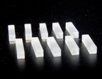
Frequency Doubling Crystal
Frequency Doubler or Second Harmonic Generation (SHG) is a special case of sum frequency generation if the two input wavelengths are the same. The simplest scheme for frequency doubling is extracavity doubling. The laser passes through the nonlinear crystal only once. However, if the power density of laser is low, focused beam, intracavity doubling and external resonant cavity are normally used to increase the power density on the crystals.
 | Crystals | Size(mm3) | Coating |
| LBO | 2x2x5 | AR@1064nm&532nm/946nm&473nm/1342nm&671nm | |
| 2x2x10 | |||
| KTP | 2x2x5 | AR@1064nm&532nm | |
| 2x2x9 | |||
| BBO | 2x2x5 | AR@1064nm/532nm/266nm | |
| 2x2x10 |
Lens
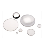 | Material: BK7 grade A optical glass |
| Design Wavelength: 546.1 nm | |
| Design Index: 1.5183 ±0.0005 | |
| Diameter Tolerance: +0.0, -0.15 mm | |
| Paraxial Focal Length: ±2% | |
| Centration: 3 arc minutes | |
| Clear Aperture: >80% | |
| Bevel: 0.25 mm x 45° | |
| Surface Quality: 60-40 scratch and dig | |
| Surface Figure: l/[email protected] |
| Lens | Part No. | Illustration | Property and Application |
| Plano-Convex Lens | L01 |  | Positive focus length. Suitable when one conjugate is more than five times the other. Also where both conjugates are on the same side of the lens. |
| Double-Concave Lens | L02 |  | Negative lens with the form suited to producing diverging light or a virtual image, where the input light is converging. |
| Plano-Concave Lens | L03 |  | Negative lens with the form suitable where one conjugates is more than five times the other, e.g. producing divergent light from a collimated input beam. |
Waveplate
 Crystalline quartz is frequently used in strictt quality retardation applications, Zero-order waveplate is made by cementing together two quartz plates with their fast axes orthogonal to each other. The difference in thickness is equal to either λ/4 or λ/2 for a specified wavelength. Compared with multiple-order quartz retarders, they are much more insensitive to the variation of retardation with wavelength, temperature and angle of incidence. Waveplates of other wavelength and sizes are custom made.
Half Waveplate
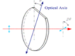 When applying a linearly polarized beam to a half waveplate, it emerges as a linearly polarized beam but its polarization plane is rotated with respect to the polarization plane of the input beam. The rotation of the polarization plane is such that the angle between the input polarization and the output polarization is twice the angle between the input polarization and the waveplate’s axis. When applying a circularly polarized beam, a clockwise circular polarization will transform into a counter-clockwise circular polarization and vice versa.
Quarter Waveplate
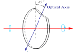 When applying a linearly polarized beam with the polarization plane aligned at 45deg to the waveplate’s principal plane, the output beam will be circularly polarized. Similarly when applying a circularly polarized beam to a ¦Ë/4 waveplate the output beam will be linearly polarized. When a quarter waveplate is double passed, i.e. by mirror reflection, it acts as a half waveplate and rotates the plane of polarization to a certain angle. Quarter waveplates are widely used in creating circular polarization from linear or linear polarization from circular, ellipsometry, optical pumping, suppressing unwanted reflection, optical isolation and etc.
Type of Waveplate
| Type | Feature | |
| Zero Order | Cemented |
|
| Optical Contacted |
| |
| Air Spaced |
| |
| True Zero Order | Cemented |
|
| Single Plate |
| |
| Multi Order |
| |
Specification
| Material: | Crystal Quartz |
| Dimension allowance: | +0.0, -0.15mm |
| Phase contrast Retardation : | λ/8,λ/4,λ/2, or discretional |
| Wavefront distortion: | ≤λ/[email protected] barring Cemented Waveplate |
| Retardation tolerance: | ≤λ/300、≤λ/500 |
| Wavelength range: | 260-1600 nm |
| Parallelism: | ≤1 arc second |
| Surface quality: | 20/10 scratches and dig |
| Clear aperture: | ≥90% |
| AR coating: | R≤0.25% at central wavelength |
Comparison of Waveplates
| Order of Waveplate | Multi | Low | Cemented Zero | Cemented Broad-band Zero |
| Total Thickness (mm) | ~1 | ≤0.5 | 1.5~2 | 1.5~3 |
| Spectral Bandwidth (nm) | 0.5 | 1.5 | 30 | 110 |
Standard Products of Multi Order Half-Waveplates
| Item No. | Dia.(mm) | Wavelength | OD | Thickness |
| HWPZ-445-12 | 12.7mm | 445nm | 1.0″ | 0.7mm |
| HWPZ-457-12 | 12.7mm | 457nm | 1.0″ | 0.7mm |
| HWPZ-473-12 | 12.7mm | 473nm | 1.0″ | 0.7mm |
| HWPZ-532-12 | 12.7mm | 532nm | 1.0″ | 0.7mm |
| HWPZ-589-12 | 12.7mm | 589nm | 1.0″ | 0.7mm |
| HWPZ-638-12 | 12.7mm | 638nm | 1.0″ | 0.7mm |
| HWPZ-671-12 | 12.7mm | 671nm | 1.0″ | 0.7mm |
| HWPZ-914-12 | 12.7mm | 914nm | 1.0″ | 0.7mm |
| HWPZ-946-12 | 12.7mm | 946nm | 1.0″ | 0.7mm |
| HWPZ-1064-12 | 12.7mm | 1064nm | 1.0″ | 0.7mm |
| HWPZ-1122-12 | 12.7mm | 1122nm | 1.0″ | 0.7mm |
| HWPZ-1342-12 | 12.7mm | 1342nm | 1.0″ | 0.7mm |
Filter
Absorption, and particularly wavelength selective absorption is an important factor in the function of the filters. Two commonly used absorbers are thin metallic films which are particularly insensitive to wavelength for absorption, and colored glasses which absorb wavelengths varied by as much as several orders of magnitudes in only tens of nanometers. Interference filters are multilayer dielectric thin film devices. Metallic films, colored glasses and thin dielectric films are used in CNI filters.
Band Pass Filters
 | Applications: |
| Emission filters in fluorescence | |
| Sorting filters in photometry | |
| Stray light or trim filters | |
| Eliminate unwanted near band radiation |
Specification (Cut-on λc) | λ (nm) | Transmittance |
| Filter for 473/ 532 nm laser (Filter-473/ 532) | 700 | 0.01 |
670 | 0.06 | |
570 | 0.82 | |
530 | 0.97 | |
| 470 | 0.97 | |
420 | 0.90 | |
| 350 | 0.65 | |
| 320 | 0.04 |
| Filter for 671 nm laser (Filter-671) | 1060 | 0.01 |
780 | 0.37 | |
| 670 | 0.77 | |
| 660 | 0.82 | |
650 | 0.82 | |
630 | 0.87 | |
| 560 | 0.97 | |
530 | 0.95 | |
| 370 | 0.94 | |
| 280 | 0.01 |
| Filter for 1064 nm laser (Filter-1064) | 2700 | 0.83 |
| 1900 | 0.98 | |
| 1300 | 0.98 | |
1060 | 0.98 | |
| 980 | 0.97 | |
950 | 0.97 | |
860 | 0.75 | |
840 | 0.25 | |
| 800 | 5×10⁻⁴ |
Line Generator
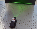 CNI can offer line lasers at all existing wavelengths and output power, also the divergence are available infan angles of 5°, 7°, 10°, 30°, 45°, 60°, 75°, 90° and 100° for custom applications. These series lasers can be used to display a uniform straight reference line for use in alignment, machine vision systems, construction and process control.
Specification
| Part No. | Full fan Angle (α°) | Material |
| LG## | 7°, 10°, 30°, 45°, 60°, 75°, 90° | BK7 |
Note: Other sizes, angles are available upon request
Beam Splitter & Combiner

- Superior broadband performance
- Extinction ratio >500:1, 1000:1 average
- Low wavefront distortion
Product Detail
Broadband polarizing cube beamsplitters provide efficient polarization for use with multiple or tunable sources. Each polarizer consists of a pair of precision right-angle prisms carefully cemented together to minimize wavefront distortion. The hypotenuse of one of the prisms is coated with a multilayer dielectric polarizing beamsplitter coating optimized for a broad wavelength range. The four faces are antireflection coated with a multilayer dielectric coating to minimize surface reflection losses. An unpolarized beam is split into two orthogonal, linearly polarized components. P-polarized light is transmitted, while s-polarized light is reflected, both with negligible absorption. The extinction ratio is better than 500:1, yet it averages 1000:1. This unique component provides all the benefits of a broadband polarizer in a standard cube configuration. Broadband polarizing cube beamsplitters are available in four wavelength ranges covering the visible through near infrared. They are offered in two sizes:12.7 and 25.4 mm.
Specification
| Material | BK7grade A optical glass, Fused silica |
| T/R: | 50/50±5% for specified wavelength R=”(Rs+Rp)/2,T=(“Ts+Tp)/2 |
| Incidence Angle: | 0°±2° |
| Beam Deviation: | 0°±3′(T),0°±5′(R) |
| Coatings: | dichroic multiplayer beamsplitter film on hypotenuse, AR film on the four polished surfaces of the prism |
| Surface Flatness: | 0.3-3 |
| Surface Quality: | 20/10 to 80/50 |
| Clear Aperture: | >90% dimension |
| Application: | Spectrophotometer, interferometer, tunable laser etc. |
Dimension, T/R, incident angle, wavelength range or other specs are available upon request.
Standard Wavelength
| Narrow Band | 532, 632.8, 780, 850, 1064, 1550nm |
| Broad Band | 450-650, 650-900, 900-1200nm |
Mirror & Windows
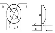
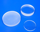 | No | A (mm) | B (mm) | C (mm) | D | E | Material |
| 1 | 26±0.2 | 4.6±0.2 | 1.8±0.2 | ¢22 | ¢33-0.1 | H-K9L (or H-BaK7) | |
| 2 | 24±0.1 | 4±0.05 | 1.15±0.2 | ¢22 | ¢34-0.1 |
 Specification
AR coating (400-700nm) R≤0.5% Metal Reflecting T≤0.5%
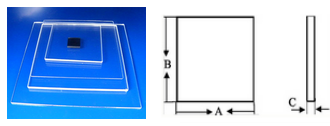
| No | A (mm) | B (mm) | C (mm) | PV Value | Material | |
| 1 | 5.0±0.1 | 5.0±0.1 | 0.7±0.1 | <0.02 (Test by ZRGO Test area 5×5) | Coating on side (532nm, 635nm, 808nm, IR-CUT) | B270 (H-K9L) Soda Lime |
| 2 | 20±0.1 | 20±0.1 | 1±0.02 | |||
| 3 | 80±0.1 | 80±0.1 | (0.5,0.7,1.0,1.5,1.7,2.0,3.0mm)±0.03 | |||
| 4 | 76±0.1 | 76±0.1 | (0.8,1.0,1.5,2.0,2.5mm)±0.03 | |||
| 5 | 60±0.1 | 60±0.1 | 5.6±0.03 | 2.02 | 808nm±45: R≥98% | H-K9L |
| 6 | 11.6±0.1 | 11.6±0.1 | 2.2±0.03 | AR | ZAB25 | |
| 7 | 5.2±0.05 | 5.2±0.05 | 1±0.03 | 0.02 | Coating MgF2 | Quartz glass |
 Specification