All you need to know about g-code generation using an Inskcape + J Tech Photonics plugin
(all software can be downloaded from our download center)
The drawing should have a clear continuous contour. In addition to the circuit, there should be nothing superfluous. If the picture is translated by scanning / photographing, it is recommended to circle the outline with a black pen, a thin marker, or something similar. Ideally, if the final pattern is monochrome (or b / w).
Download the drawing in Inkscape.
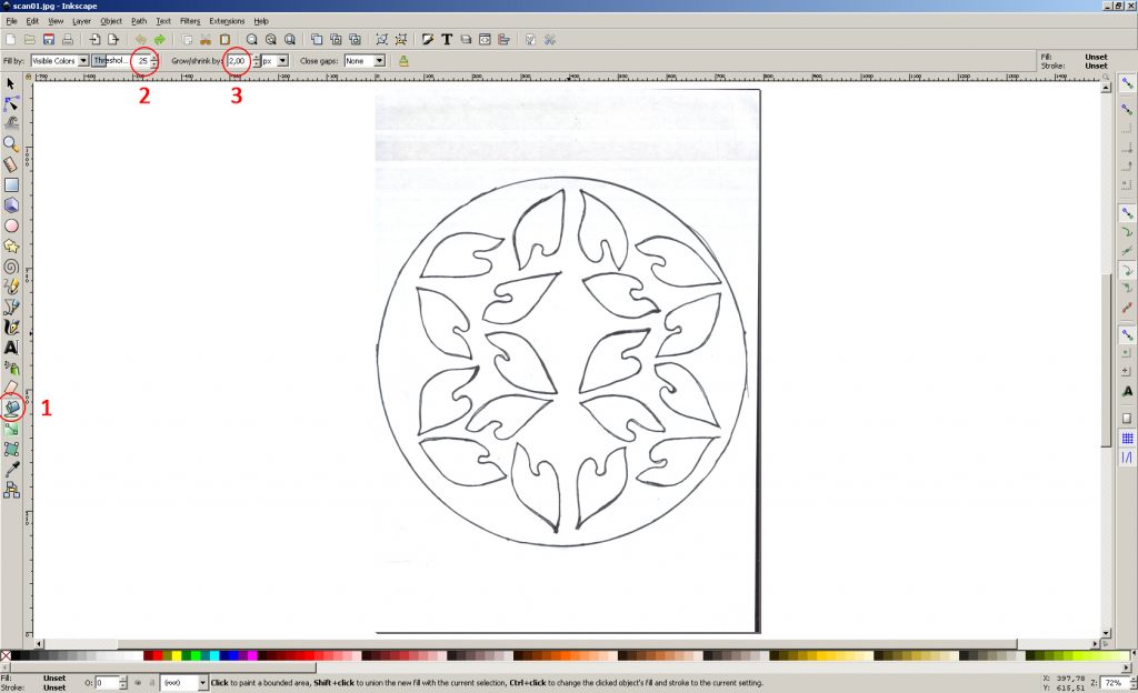
1. Use the “Fill bounded areas” tool
2. The parameter “Threshold” – 25 (determines the difference between the selected pixel and the neighboring ones that fall into the fill. It may depend on the particular picture. With a lower value, gray spots may appear in the flooded area, which, due to the color difference, are not flooded. With a larger value can fill the entire picture through the contour)
3. The parameter “Grow / shrink” – 2px (increases the flooded area along the contour by 2 pixels. If the outline of the stroke is thin, you can set it to 0)
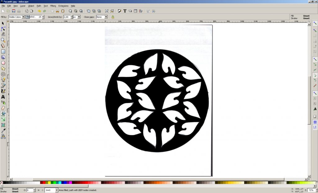
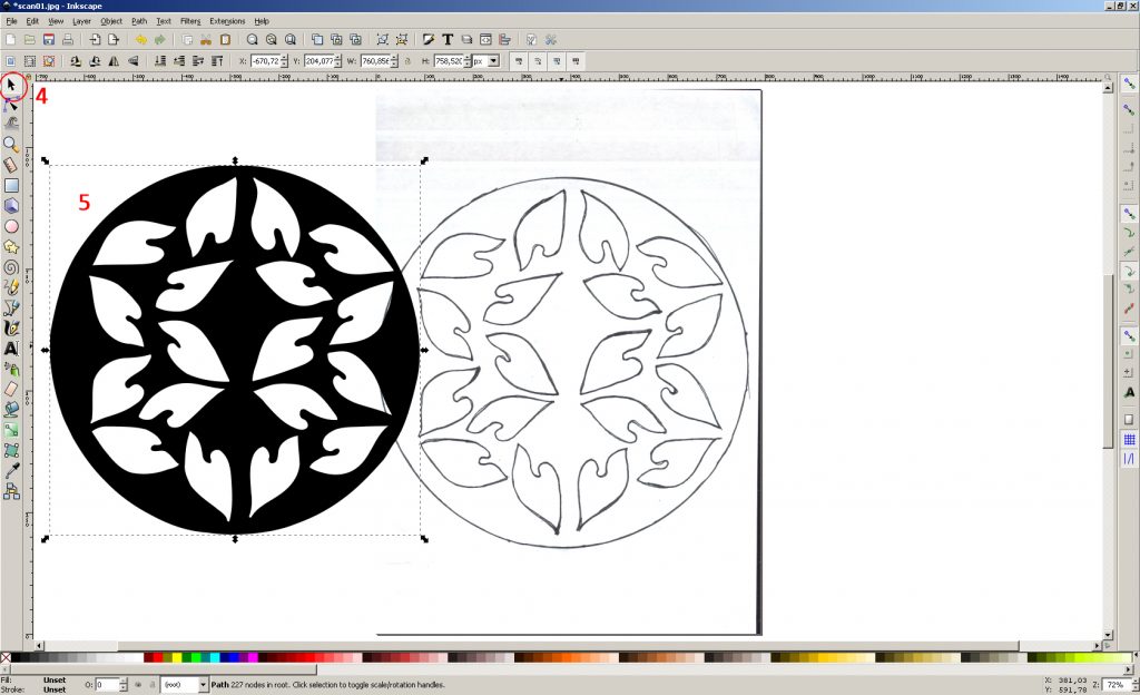
4. Use the “Select and transform objects” tool
5. Clamp on the flooded area of LMC and drag one of the layers to the side
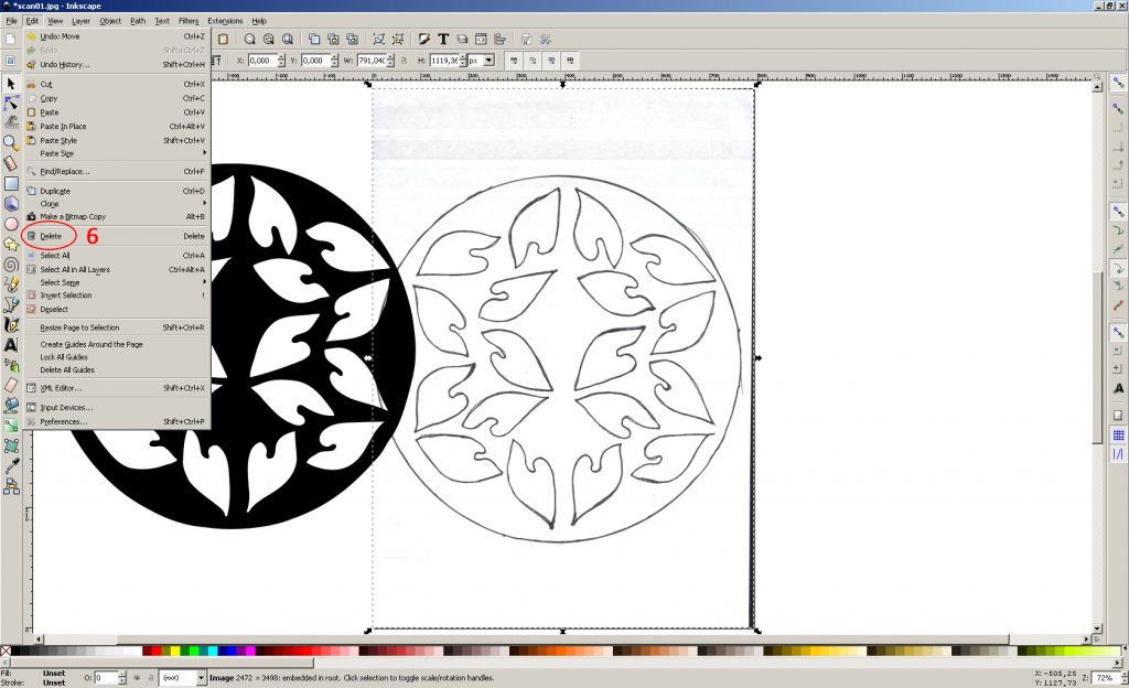
6. select LMB layer with the original image and delete it (Menu “Edit-> Delete”)
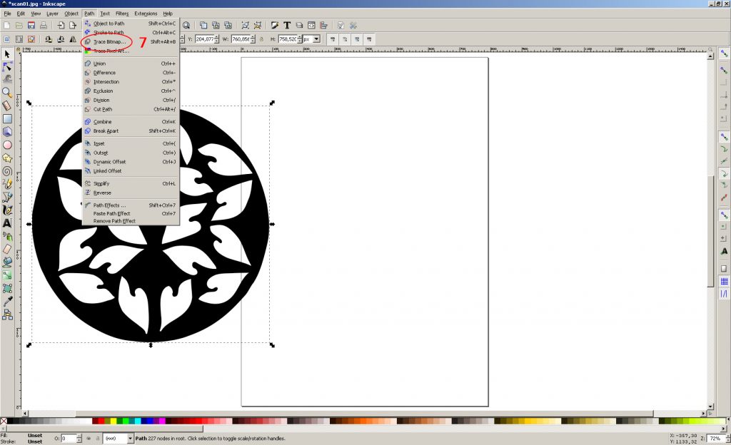
7. Select the layer with LMB fill and open the image vectorization window (Menu “Path-> Trace Bitmap …”)
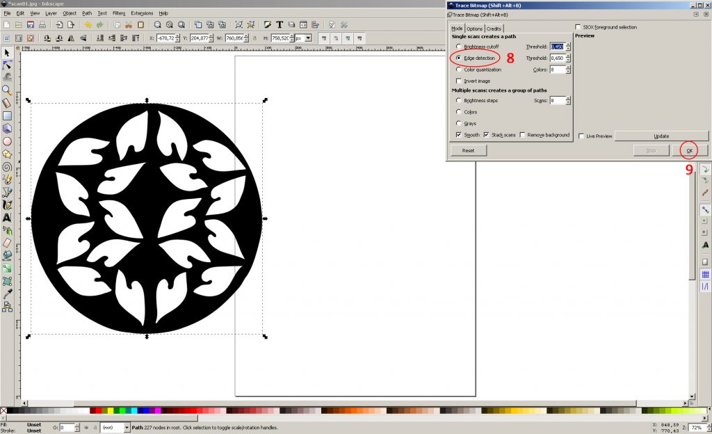
8. use the “Edge detection” method. We leave the settings by default.
9. Click “OK” and close the “Trace Bitmap” window
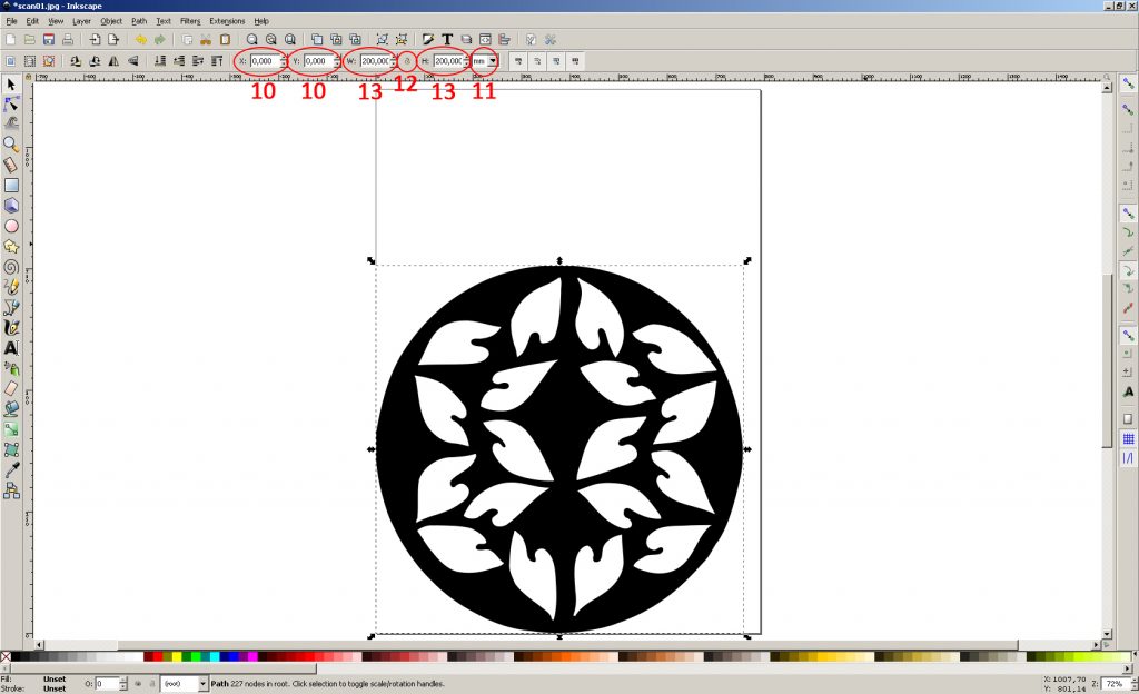
10. Set the initial coordinates of the layer x = 0, y = 0
11. Choose a measurement of the size of the layer in mm
12. Check that the option to save aspect ratio is disabled (Since the drawing was drawn and circled in manually, slight deviations from the size 200x200mm, which should be) are possible
13. Set the width and height of the layer 200mm
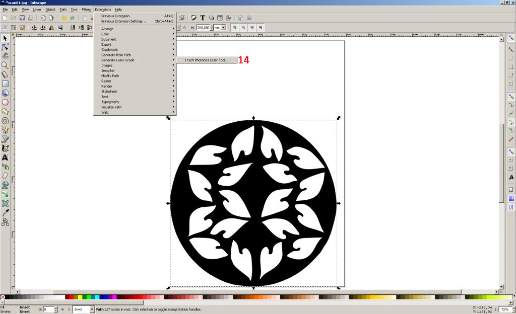
14. Open the G-code plugin (Menu “Extensions-> Generate Laser Gcode-> J Tech Photonics Laser Tool …”)
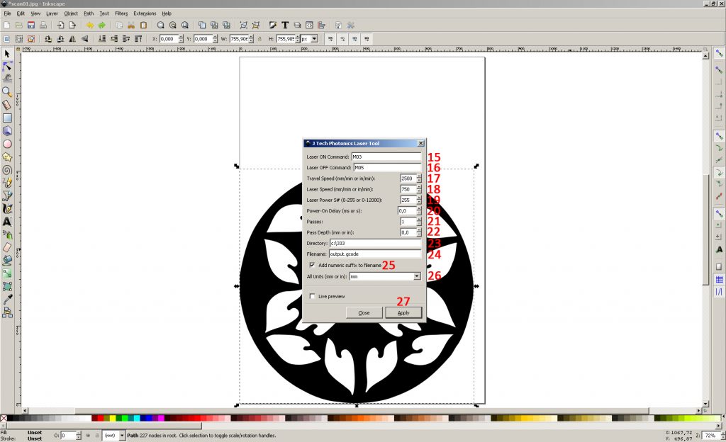
15. Laser turn-on command – M03
16.Laser off command – M05
17. The speed of movement with the laser off (idling) – 2500 (depending on the particular machine)
18. The speed of movement with the laser on (stroke) – 750 (depending on the material)
19. Laser power – 1000 (depending on the version of the plug-in, it can be indicated in% or specific numbers)
20. The delay before movement after turning on the laser is 0 (it makes sense when milling)
21.Number of passes – 1
22. Lowering the laser along the Z axis after each pass – 0 (not used in this case)
23. File Location
24. File Name
25.adding a numerical suffix to the file name (it is convenient that you do not overwrite the name each time, the number at the end of the file name simply increases)
26. Unit of measurement – mm
27. G-code generation
Perhaps the necessary changes to the G-code (depending on the version of the plugin)
We use the notepad and the quick change command “Ctrl + H”. All replacements are for example purposes only.
I. If the laser power is specified in%, a G-code can be generated indicating the power 0-255 where 255 corresponds to 100%. Depending on the machine, it may be necessary to replace parameter S255 with S1000.
II. The maximum stroke speed in the plug-in can be limited to 1000. To set a higher speed, you will need to replace the F750 parameter with the F1750.
III. The plugin can use the G0 command to work on straight segments. Since this command is used to idle, the following are possible:
a) The passage will be carried out at a speed of idle, not working speed.
b) Some machine control programs can turn off the laser on the G0 command (100% not taken into account, just an assumption, because I came across a G-code where exactly such work was meant).
To avoid this, replace the command G0 with G1
IV. Specifically, when using the GrblControl control program, it is recommended to add the line “G0 X0 Y0 Z0” to the beginning of the G-code. This does not affect the operation of the machine itself, but it allows you to display the G-code graphically in the program window, as well as see its visual performance