An Endurance Mo2 PCB – your advanced laser driver
All you need to know about Endurance laser boxes
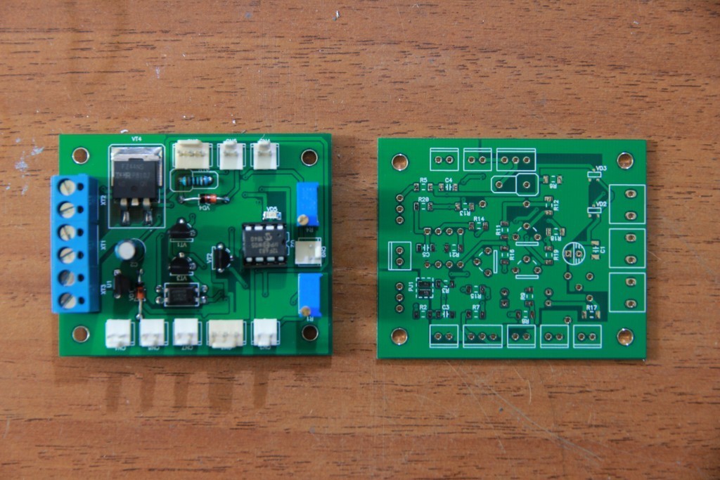
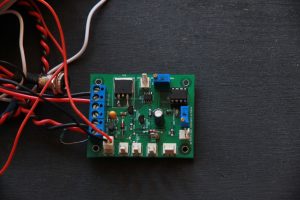
An Endurance MO2 PCB is ready
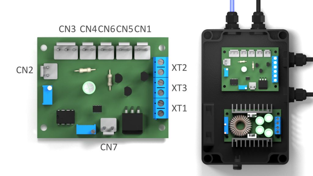
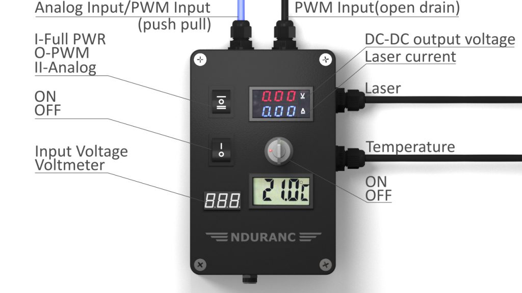
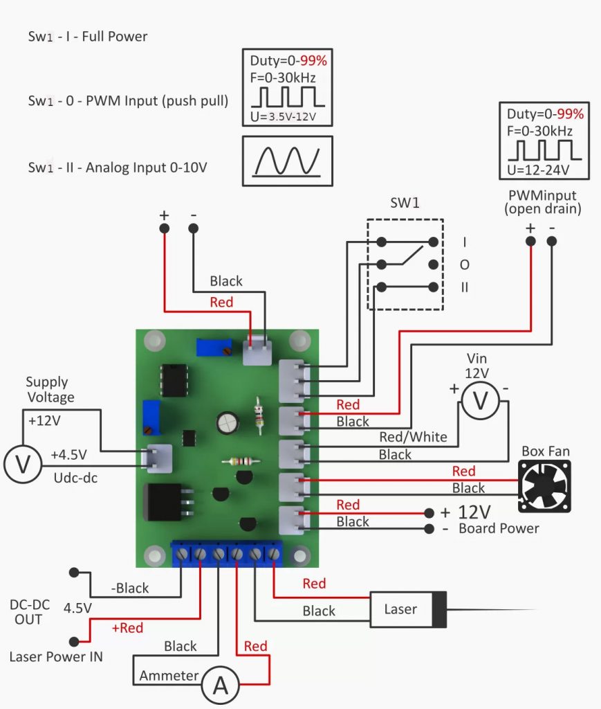
CN1 – Power Board +12V
CN2 – Analog Input/Inverted input
CN3 – Mode select switch SW1
CN4 – PWM Input
CN5 – Fan
CN6 – Input Voltage Voltmeter
CN7 – DC-DC output voltage voltmeter
XT1 – DC-DC
XT2 – Laser
XT3 – Laser current measurement. Ammeter
In addition to an Endurance MO1 PCB there will be a converter analog into into PWM.
Analog input 0-10V. PWM output: 0-100%.
Analogue is planned in PWM, TTL in PWM (as in the Endurance MO1 board), the choice of input for operation (analog or TTL) is planned to be automatically (by the presence of a signal there or there) overvoltage protection on a laser adjustable 4.5V to 5.5V. Add an LED for the indication (needed at the setup stage).
While in the layout we will check the work from the reversal of the inputs, we also plan TTL input from 2-3V to 24V without any changes in the scheme by the end-user.
It should be great)
A Full review of an Endurance MO2 PCB by Graham Ham
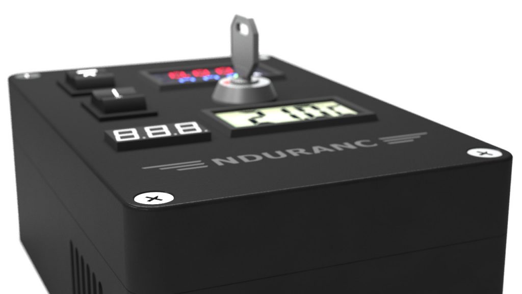
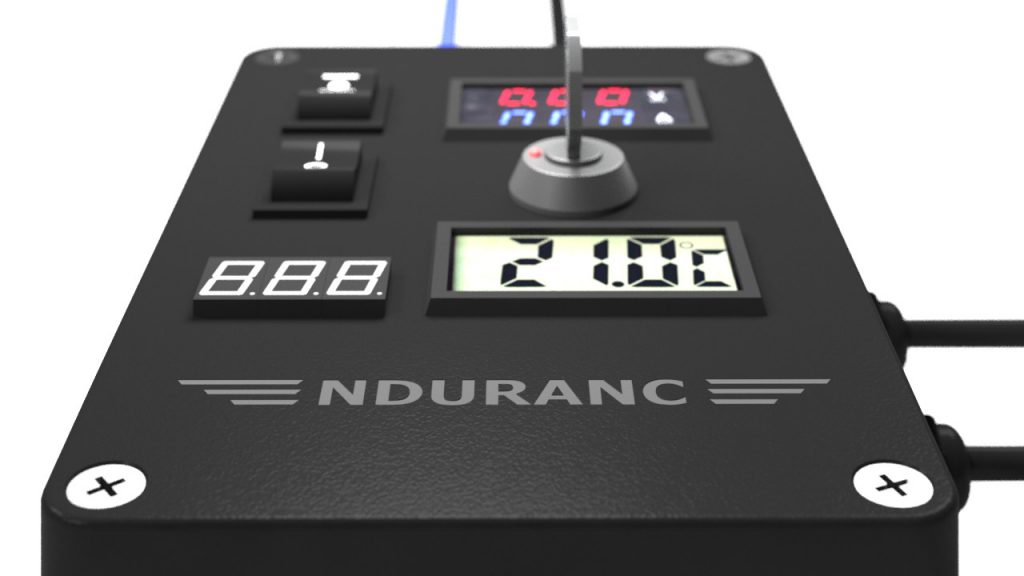
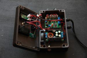
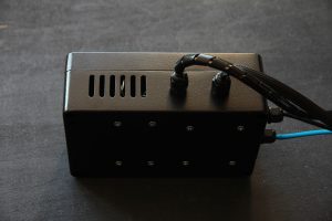
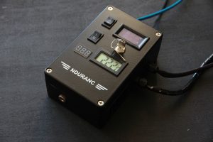
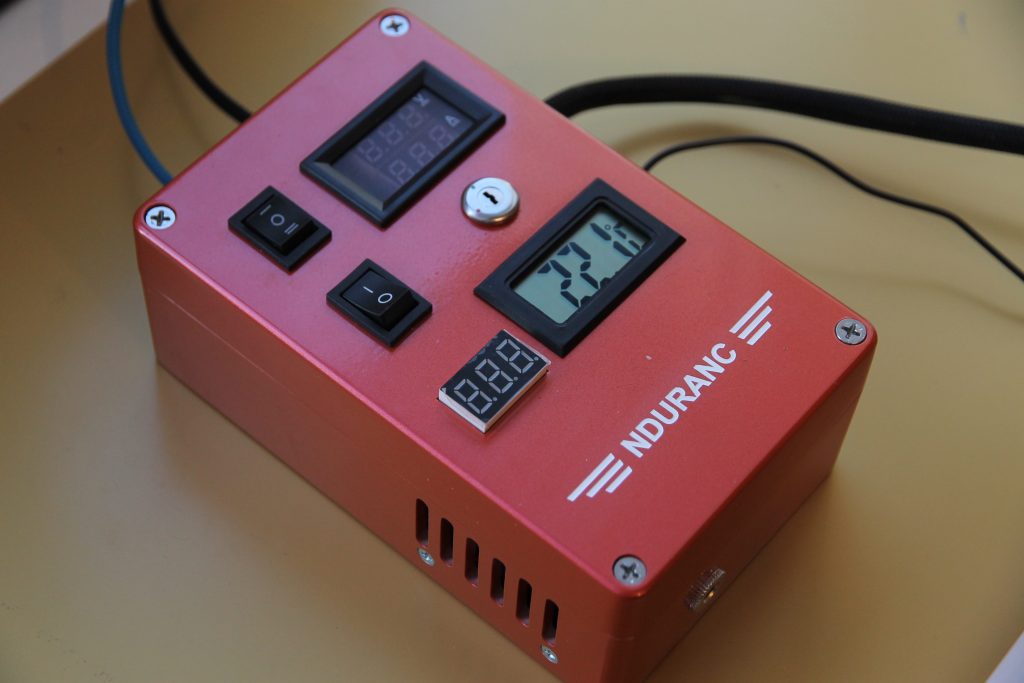
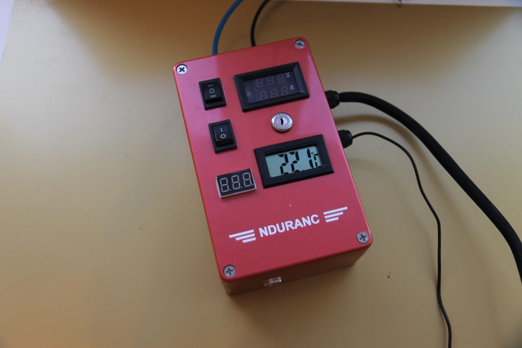
New aluminum laser box with MO2 PCB inside
PWM test on an Endurance 10 watt PLUS PRO laser. High-speed PWM with Mo2 PCB (inside laser box ver 2.0)
Zener diode will be replaced with the multi-protection option if the voltage exceeds 5-5.5V
Key features of an Endurance MO2 PCB:
1. Analog input 0-10 PWM output 0-100%.
2. TTL input up to 24V PWM output.
3. Focusing mode laser PWM 0.1%.
4. Adjustable laser voltage threshold of 4.5 to 5.5V
5. Protection against reverse polarity reversal of analog, comparator and TTL inputs.
6. The delay in applying the voltage to the laser when the unit is turned on 1.5 sec.
7. Ability to install both large and small box without modifications of the printed circuit board.
8. Ability to run an impulse mode with a wide variety of frequency and duration width.
Impulse mode
Further development of an Endurance MO3
1. Everything the MO2 PCB has.
2. Current protection and laser overload indication.
3. Protection by laser temperature + overheat indication.
4. Counter laser operating hours.
5. Display of all parameters (voltage, current, temperature, etc.) on one LCD display.
6. Possibly exclude an Arduino board.
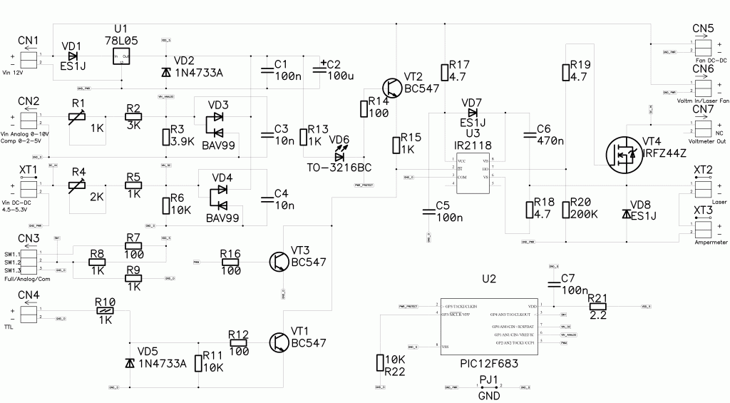
Schematics of an Endurance Mo2
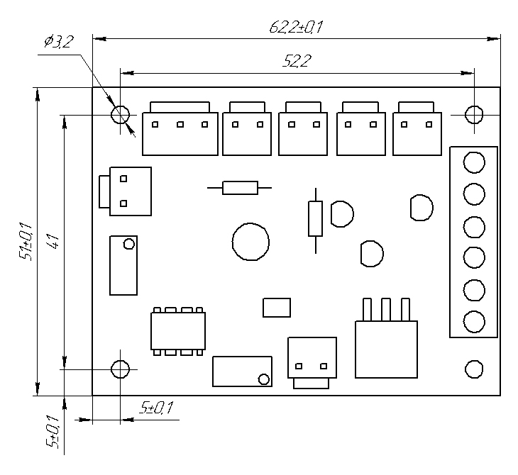
Mo2 PCB weight 26 grams
Lax box ver 2.0 size 160x100x60. (weight of a laser box ver 2.0 is 850 grams)
Technical Data for an Endurance Laser box ver. 2.0
| Supply voltage | 12 VDC+-10% |
| Minimum Current Power Supply (For laser diodes up to 10W) | 5 A+-10% |
| Rated Output Current (For laser diodes up to 10W) | 5 А |
| Max Output Current (Power supply current must be at least 10A) | 8 А |
| Laser diode voltage max | 5.5V |
| Laser diode voltage min | 2V |
| Laser diode current | 1A – 6A |
| Laser diode current max | 8A* |
| Max. PWM Frequency | 50 KHz |
| Min. PWM Frequency | 90 Hz |
| (You need to know if you connect to a 3D printer controller) | |
| Maximum PWM duty cycle | 99,90% |
| (PWM frequency over 90Hz) | |
| PWM Input Voltage (Left, Blue wire) | 3.5V – 12V |
| PWM Input Voltage (Right, black wire) | 3V – 24V |
| Rise Time | 300 nS |
| (In relation to the input pulse of the PWM) | |
| Analog Input Voltage | 0V – 10V |
| PWM Duty Cycle Based on Analog Input Voltage | 0% – 99,9% |
| PWM frequency when working with analog input | 500 HZ |
| Laser focus mode | PWM Duty 0,1% |
| Protection of the output voltage of the laser diode min | 4.5V |
| Protection of the output voltage of the laser diode max | 5.5V |
| Delay range before starting the laser: | 0-1.5 sec (adjustable) |
Data & a Diagram: current with a different PWM frequency vs. PWM ratio (PDF) >>>
Order on our online store –
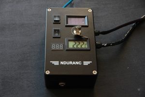
An Endurance Laser box ver 2.0
