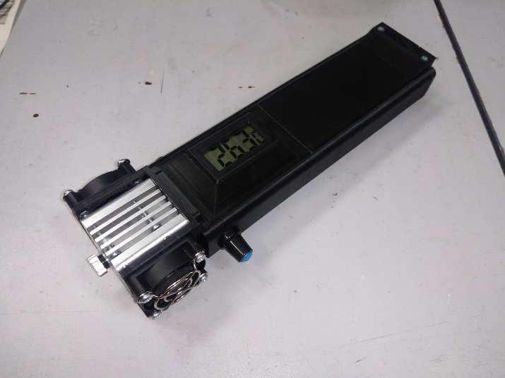
 | 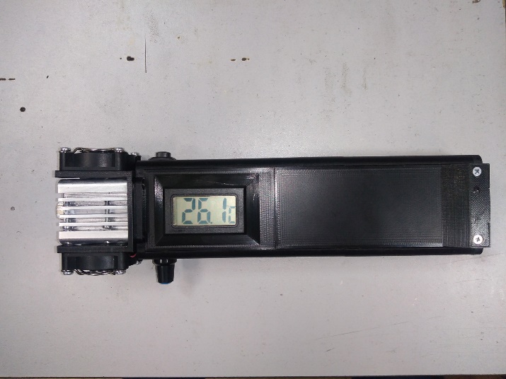 |
Components
3D printed parts:
- Frame (Part No. 1) – 1 pc.
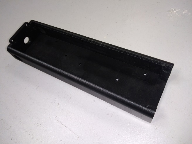 |
File – “ Laser_pointer_part-1.stl”
- Rear wall of the case (Part No. 2) – 1 pc.
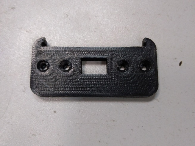 |
File – “ Laser_pointer_part-2.stl”
- Front cover (Part No. 3) – 1 pc.
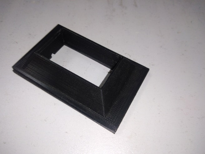 | 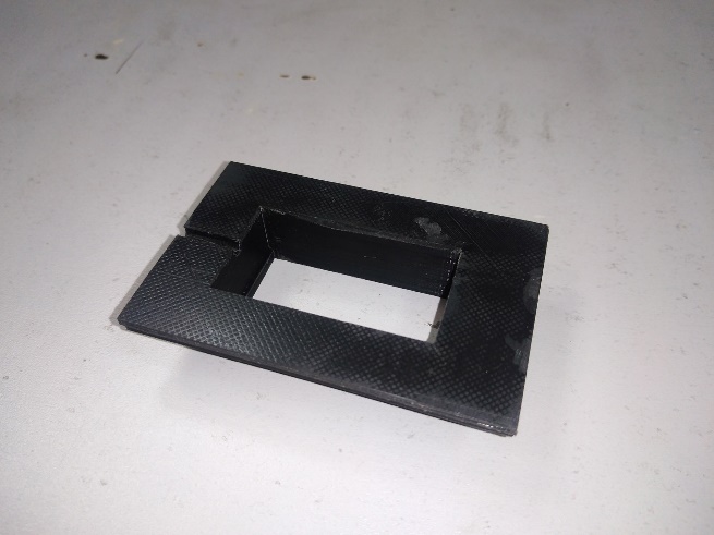 |
File – “ Laser_pointer_part-3.stl”
- Fan mount (Part No. 4) – 1 pc.
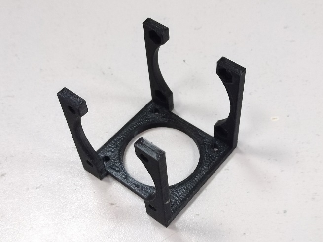 |
File – “ Laser_pointer_part-4.stl”
- Back cover (Part No. 5) – 1 pc.
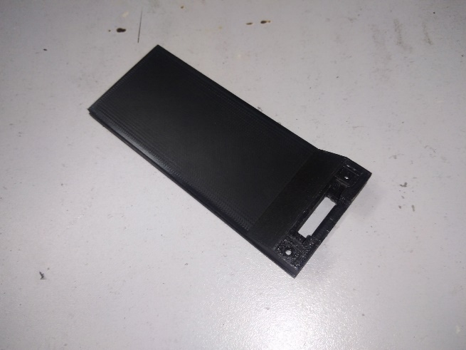 |
File – “ Laser_pointer_part-5.stl”
- Back cover retainer (Part No. 6) – 1 pc.
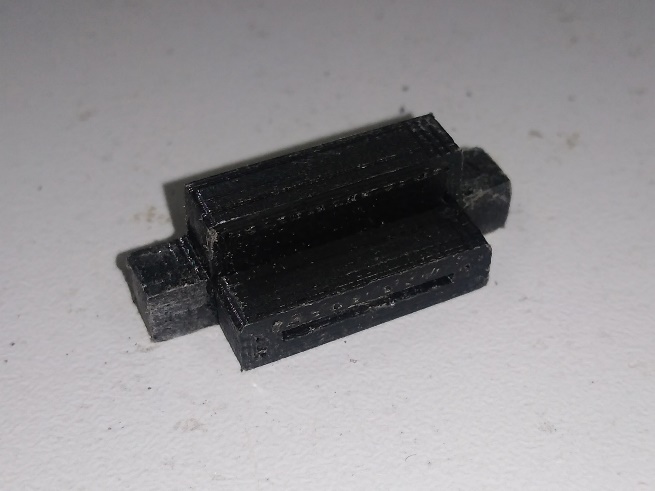 |
File – “ Laser_pointer_part-6.stl”
- Cover for the retainer (Part No. 7) – 1 pc.
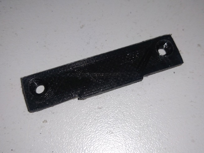 | 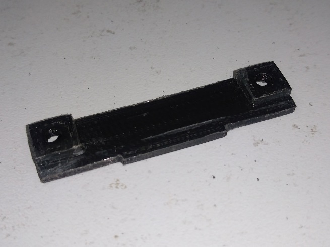 |
File – “ Laser_pointer_part-7.stl”
- Gasket for battery holder – 2 pcs
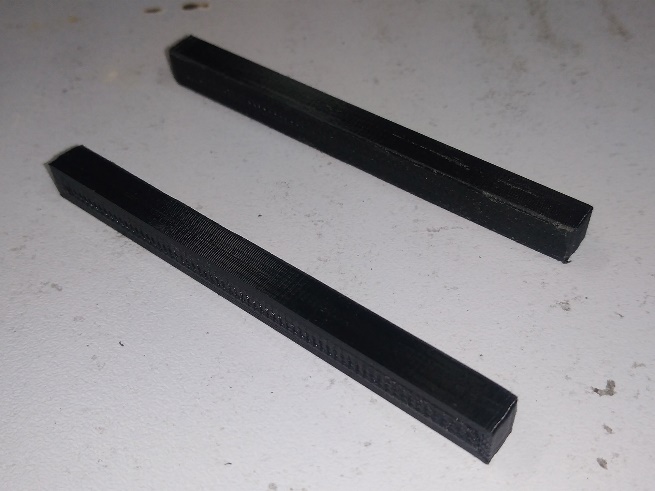 |
File – “ Laser_pointer_part-8.stl”
- Bushing – 4 pcs.
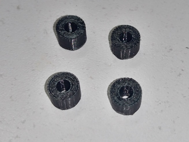 |
File – “ Laser_pointer_part-9.stl”
Electrical Circuit Components
After the name of the component, its designation on the electrical diagram is indicated in square brackets.
- Laser diode – 1 pc.
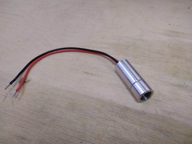 |
The pointer uses a laser diode in a cylindrical housing with a diameter of 12 mm and a length of no more than 40 mm.
Maximum current consumption: 5 A (recommended no more than 4.5 A).
Maximum voltage consumption: 5 V.
Recommended laser diode: Nichia NUBM44/47.
- Step-down DC-DC module DSN5000 / XL4005 – 1 pc
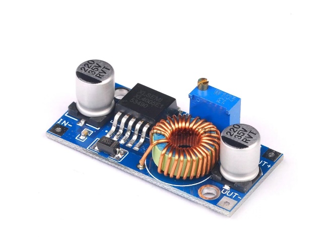 |
Output current: 5 A.
It is allowed to use another step-down DC-DC module of the same size, with the same arrangement of mounting holes.
- MO1 board from Endurance Lasers – 1 pc.
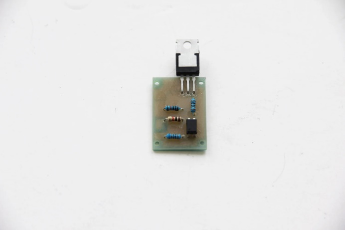 |
An Endurance Mo1 PCB – a TTL control for your laser [10 PCS]
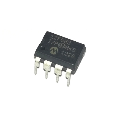
- Microcontroller PIC12F683 [U2] with firmware for Dynamic PWM Box from Endurance Lasers – 1 pc
 |
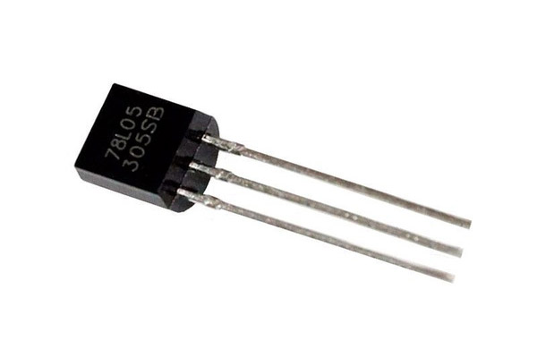
- Voltage regulator 78L05 [U1] – 1 pc
 |
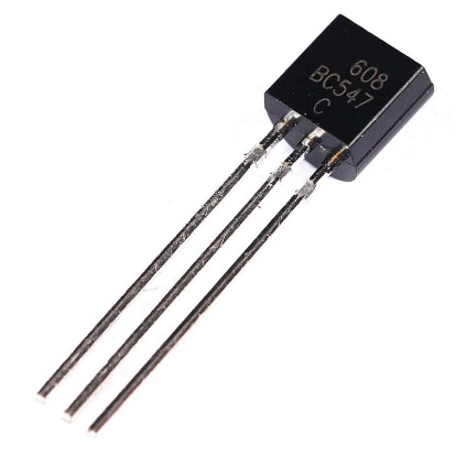
- Transistor BC547 [Q1] – 1 pc
 |
- Variable resistor B10K [R1] – 1 pc.
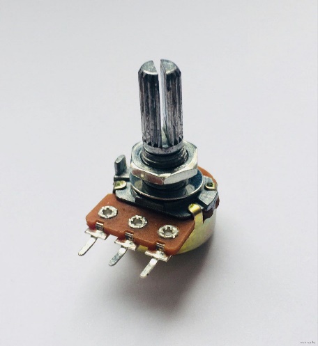 |
Nominal resistance – 10 kOhm
- Resistor 1 kOhm, 0.25 W [R2] – 1 pc.
- Resistor 100 Ohm, 0.25 W [R3] – 1 pc.
It is possible to use larger resistors, but their larger size may make them difficult to fit on the board.
- Fan [FAN1,2] – 2 pcs.
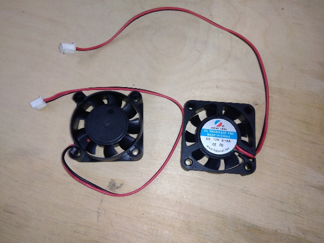 |
Supply voltage: 12 V
Current consumption: ~0.15 A
Size: 40x40x10.5 mm
- On/Off/On 3 position DPDT 2P3T PCB Panel slide switch [S1] – 1 шт
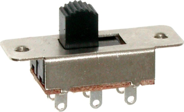 |
Overall Size: 35x12x20 mm
Knob Size: 6x5x8 mm
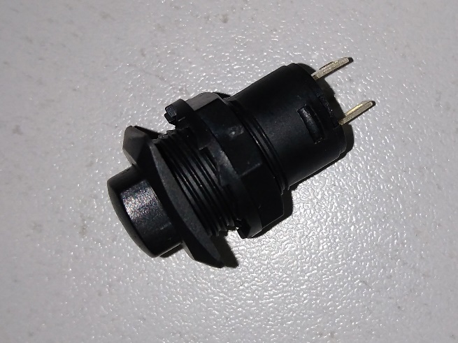
- 12mm Latching Push Button Switch [S2] – 1 шт
 |
- Open barrel female connector (terminal) 2.8mm x 0.5mm tab size – 2 шт
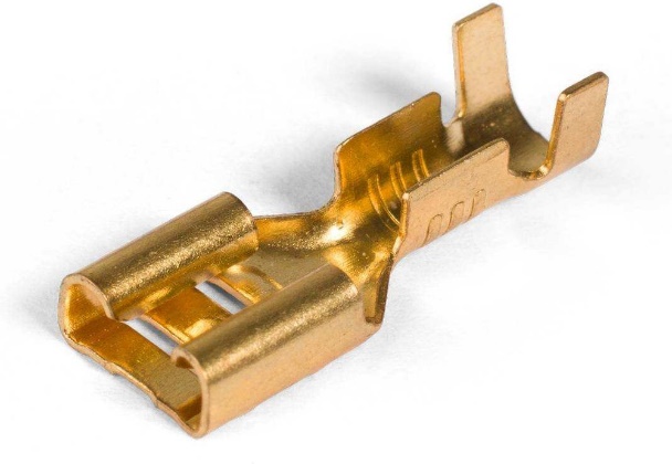 |
The terminal is used to connect the wires to the [S2] button. It is allowed to use any other suitable terminal or connect the wires to the button by soldering.
- Battery holder for 2 batteries type 18650 – 1 pc.
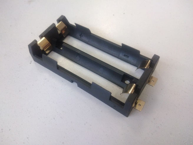 | 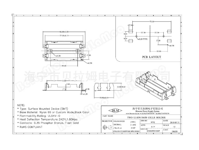 |
It is permissible to use another battery holder, provided that the overall dimensions correspond and the mounting holes are located in a similar way.
- DIP-8 IC Socket for microcontroller [U2] – 1 шт
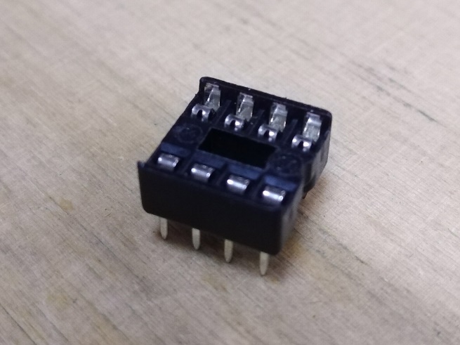 |
Pitch: 2.54 mm
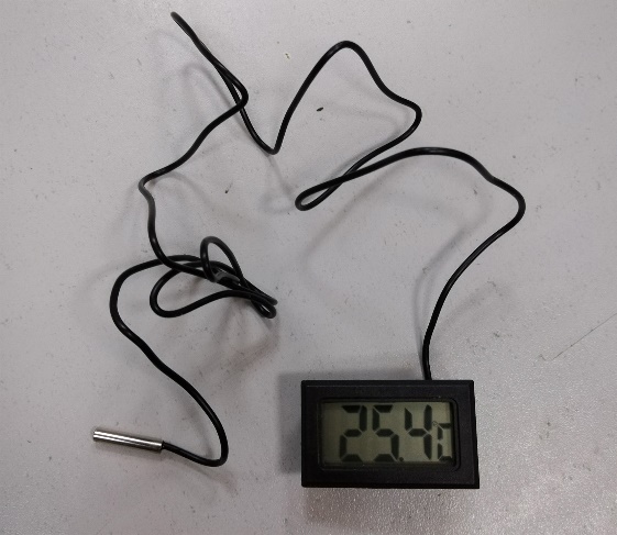
- Electronic thermometer with external temperature sensor – 1 pc.
 |
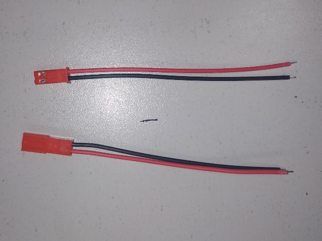
- Miniature 2-pin connector with wires – 1 pair (male-female).
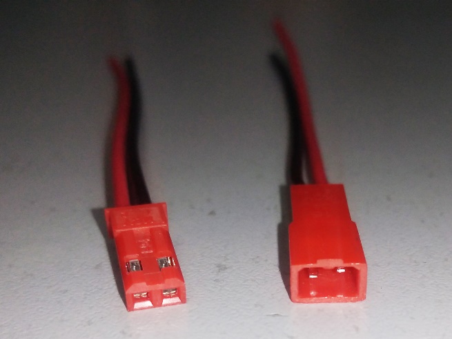 |
There are no special requirements for the appearance and shape of the connectors, except for their small size.
- Single Side Prototyping PCB Circuit Board.
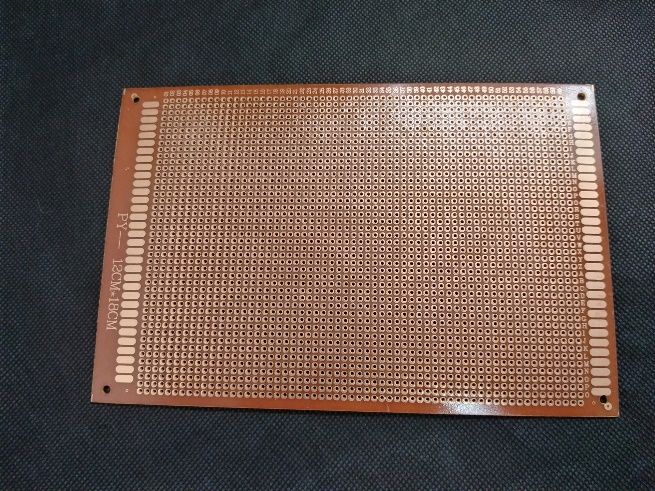 |
Hole Pitch: 2.54 mm.
Minimum size: 43×20 mm.
- AWG24 red wire – 0.5 m
- AWG24 black wire – 0.3 m
- AWG24 yellow wire – 0.2 m
- AWG18 red wire – 0.2 m
- AWG18 black wire – 0.2 m
Other components
- Small heatsink for laser module from “Endurance Lasers” – 1 шт
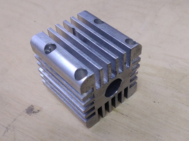 |
https://www.endurance-lasers.com/products/small-heatsink-for-laser-module-12-mm-intenal-diameter
- Protective grille for fan 40x40mm – 2 pcs.
 |
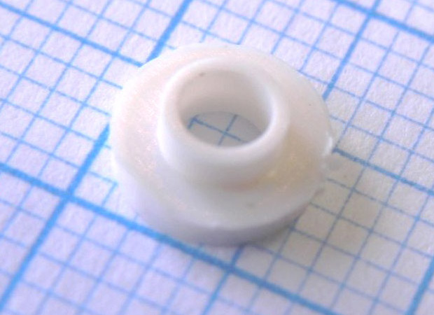
- Plastic Insulation Washer (TO-220) – 1 шт
 |
- Potentiometer control knob – 1 pc.
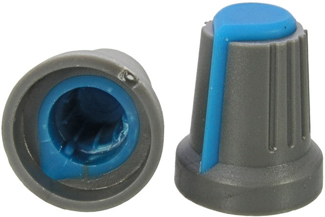 |
It is selected for the variable resistor [R1]. The diameter of the knob at its bottom should not exceed 15 mm.
- M3x6 hemispherical head screw – 2 pcs
- M3x10 hemispherical head screw – 4 pcs
- M3x10 countersunk head screw – 2 pcs
- M3x12 countersunk head screw – 6 pcs
- M3x15 countersunk head screw – 2 pcs
- M3x16 hemispherical head screw – 12 pcs
- M3 nut – 17 pcs
Also, when assembling the pointer you will need:
- Thermal paste
- Heat shrink tube with diameter of 2 and 3 mm
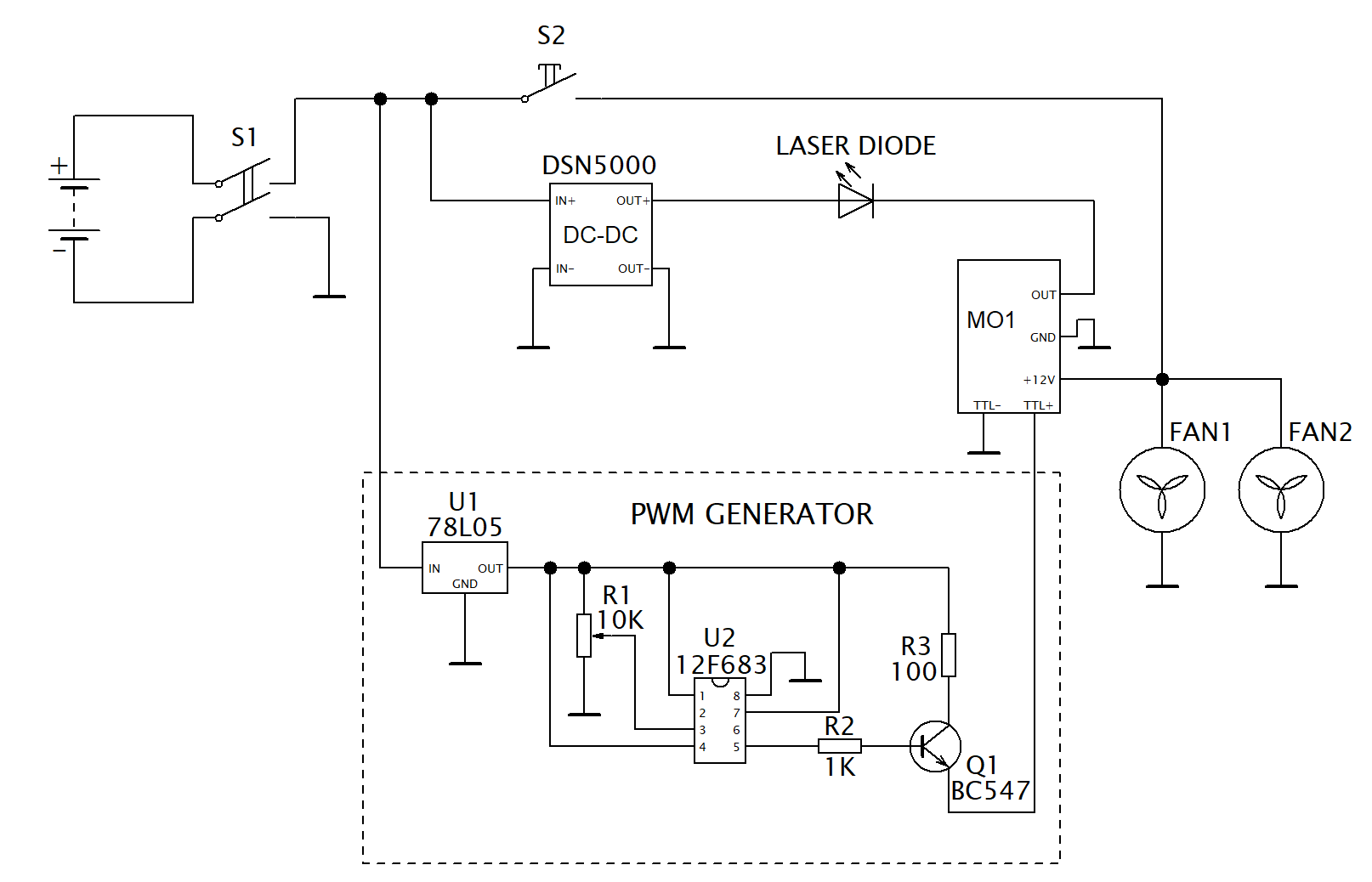
Electrical diagram of the pointer
 |
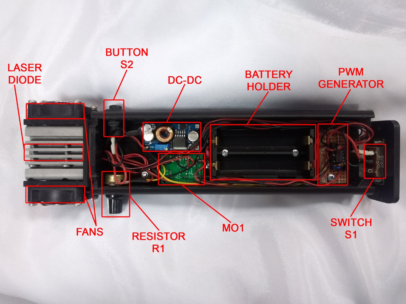
The location of the main components inside the pointer body:
 |
Assembling a PWM Generator
The laser diode in the pointer is controlled via the MO1 board using a PWM signal. The PWM generator generates the PWM signal and, using the variable resistor R1, allows the duty cycle of the PWM signal to be varied. This allows the output power of the laser diode to be varied.
The PWM generator consists of:
- Voltage regulator [U1];
- Microcontroller [U2];
- Transistor [Q1];
- Variable resistor [R1];
- Resistors [R2], [R3]
The PIC12F683 microcontroller uses exactly the same firmware as the “Dynamic PWM Box” from Endurance Lasers.
The PWM generator is assembled on a prototyping board.
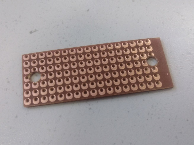
A board of approximately 43×20 mm (18×7 holes) is cut out from the prototyping board.
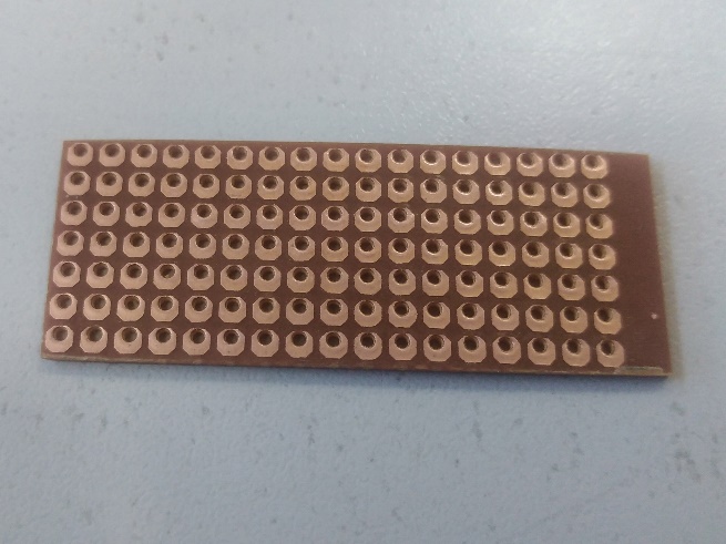 |
In the center of the short side (4th hole) and approximately in the 2nd and 17th holes along the long side of the board, mounting holes with a diameter of ~3.5 mm are drilled. The distance between the centers of the holes should be ~19.4 mm.
 |
Solder a DIP socket for the microcontroller onto the board.
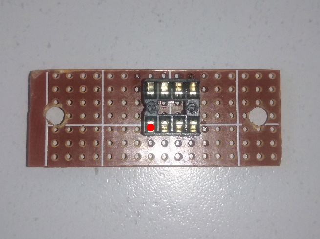 |
In the photo, the DIP socket is slightly shifted relative to the center of the board. It is desirable to place the DIP socket in the center of the board, but a slight shift from the center is allowed.
Further, in all photos of the PWM generator board assembly, the location of Pin-1 of the microcontroller [U2] on the board will be indicated by a red dot.
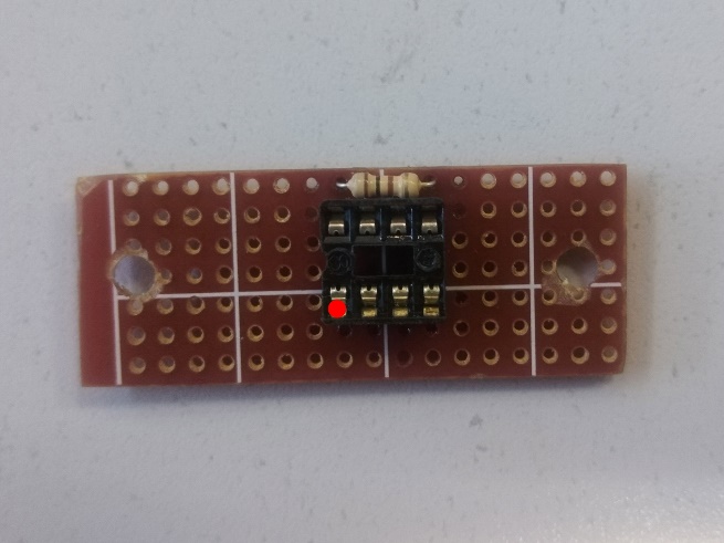
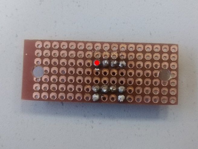
Solder the resistor [R3] to the board.
 |  |
Solder the resistor [R2] onto the board.
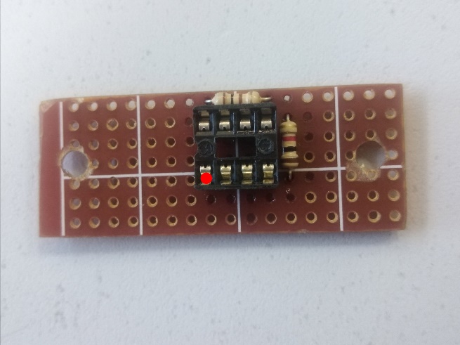 | 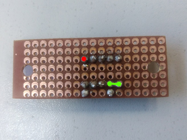 |
According to the diagram, connect one leg of the resistor [R2] to Pin-5 of the microcontroller [U2].
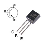
Solder the transistor [Q1] to the board.
 BC547 pinout | |
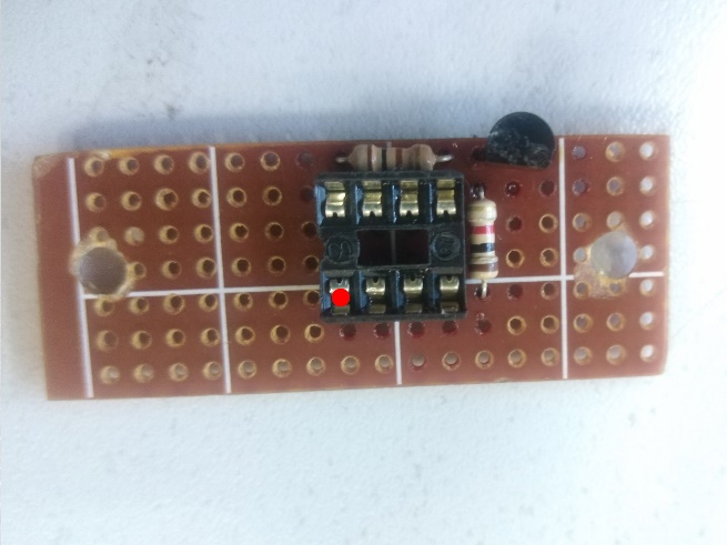 | 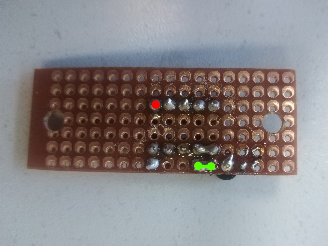 |
According to the diagram, connect the resistor terminal [R3] to the transistor collector [Q1].
Solder the voltage regulator [U1] to the board.
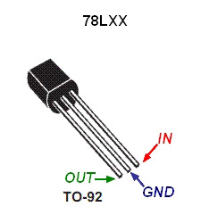 78L05 pinout | |
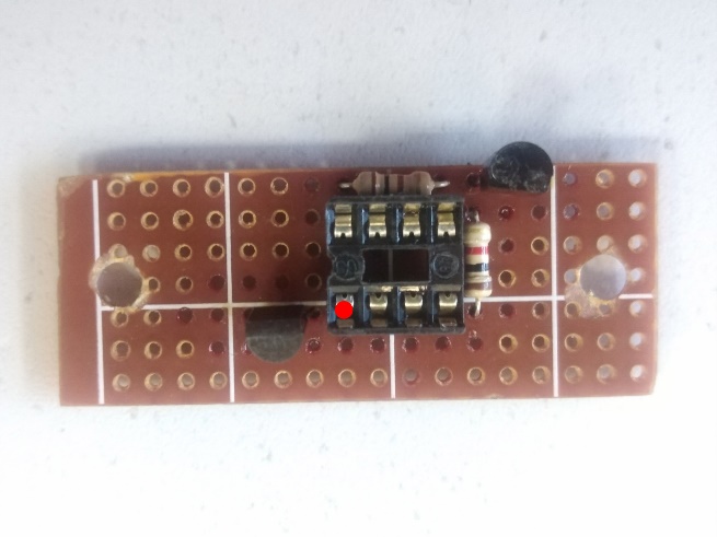 | 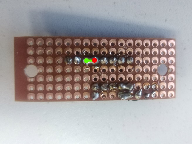 |
According to the diagram, connect the ‘OUT’ pin of the voltage regulator [U1] and Pin-1 of the microcontroller [U2].
Connect the second pin of the resistor [R2] to the Base of the transistor [Q1].
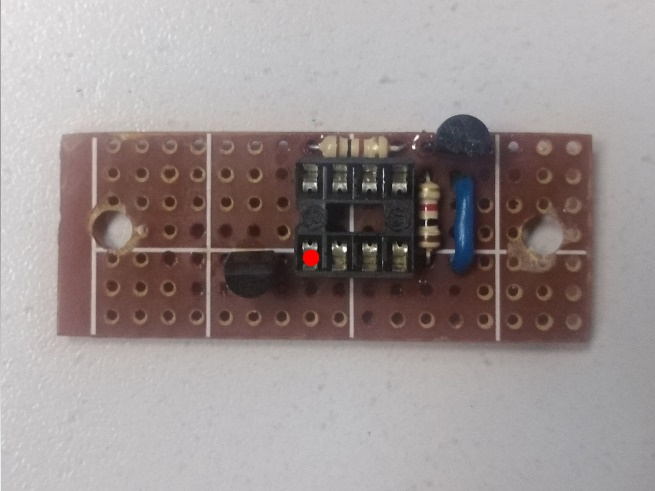 | 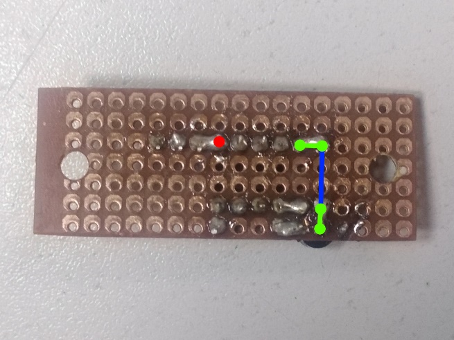 |
The resistor terminal [R3] and the transistor base [Q1] are not in adjacent holes. A wire was used to connect them. The most common color scheme for wires in electrical circuits is red wire – positive, black wire – negative. For this connection, a neutral blue wire was chosen (you can use a wire of any other color). AWG24 wires are used when assembling a PWM generator.
Connect the second terminal of the resistor [R2] and the ‘OUT’ terminal of the voltage regulator [U1].
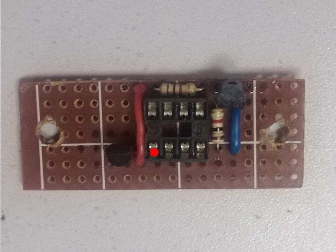 | 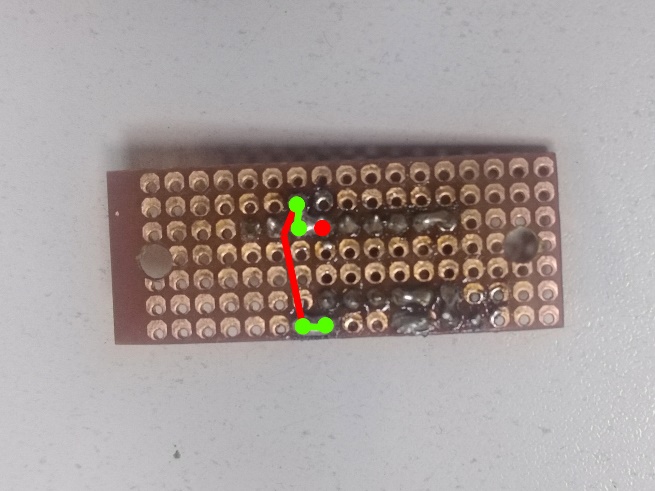 |
Connect contacts Pin-1, Pin-4 and Pin-7 of the microcontroller [U2].
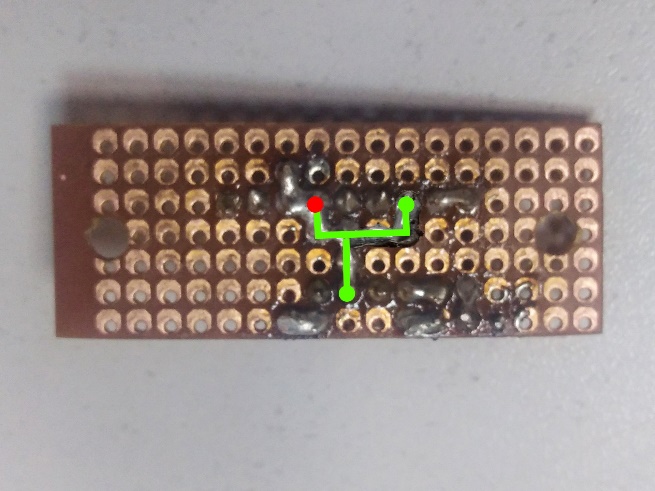 |
Connecting these contacts with wires is difficult, so solder tracks are laid along the free holes of the prototype board.
Connect the ‘GND’ pin of the voltage regulator [U1] and the Pin-8 contact of the microcontroller [U2].
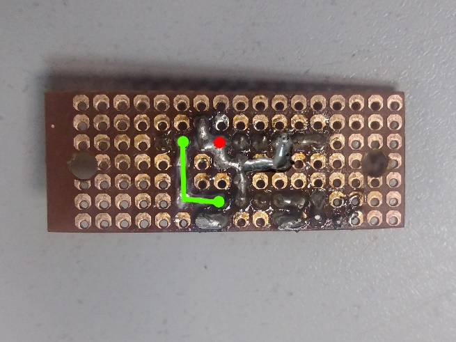 |
Solder the red wire to the Pin-1 contact of the microcontroller [U2];
Solder the yellow wire to the Pin-3 contact of the microcontroller [U2];
Solder the red wire to the Emitter of the transistor [Q1].
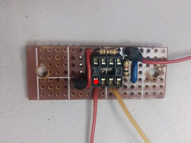 | 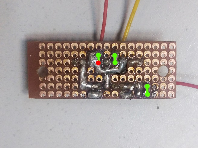 |
The red and yellow wires soldered to the contacts of the microcontroller [U2] will be connected to the resistor [R1]. The color of the yellow wire is chosen as neutral for ease of assembly. The red wire soldered to the Emitter of the transistor [Q1] will be connected to the MO1 board. The length of the wires is selected taking into account the location of the PWM generator, resistor [R1] and the MO1 board inside the pointer case + a small reserve so that the wires are not in a taut state when installing the components in the case. But too long wires are also undesirable, since the space inside the case is limited and the wires can interfere.
Assembling the pointer
The following sequence of assembly stages of the pointer is conditional and most of the stages can be performed in a different order.
When assembling the pointer, wires of two colors are used: the red wire connects the positive contacts of the components, the black wire – the negative (GND).
The length of the wires connecting the components of the pointer is selected “on site” with some reserve so that, if necessary, the excess can be cut off from the wire and it does not have to be extended.
Using AWG18 wire, connect two adjacent terminals of the battery holder in order to connect the installed batteries in series.
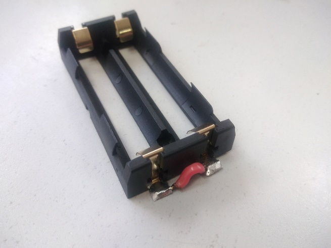 |
Solder the switch [S1] to the opposite terminals of the battery holder using AWG18 wires. The wires are soldered to the central terminals of the switch [S1]. The soldering point with the contacts of the switch [S1] is insulated using heat shrink tubing.
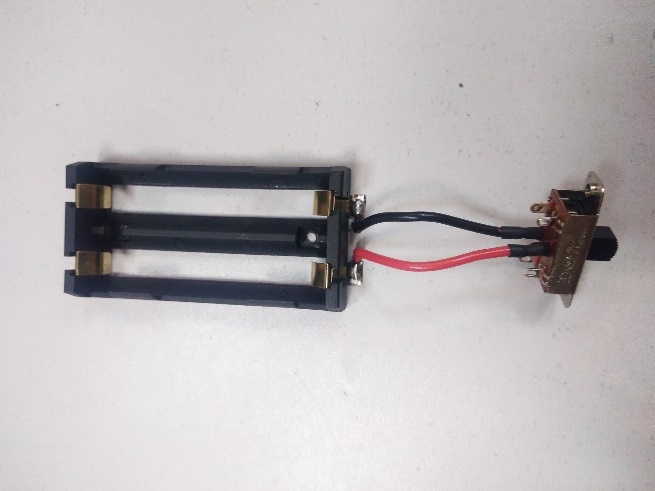 |
The length of the wires is selected so that the switch [S1] protrudes beyond the body of the pointer by approximately 10-20 mm.
Solder two pairs of wires to the side terminals of the switch [S1]. Each pair consists of an AWG18 wire and an AWG24 wire. The soldering point is insulated using heat shrink tubing.
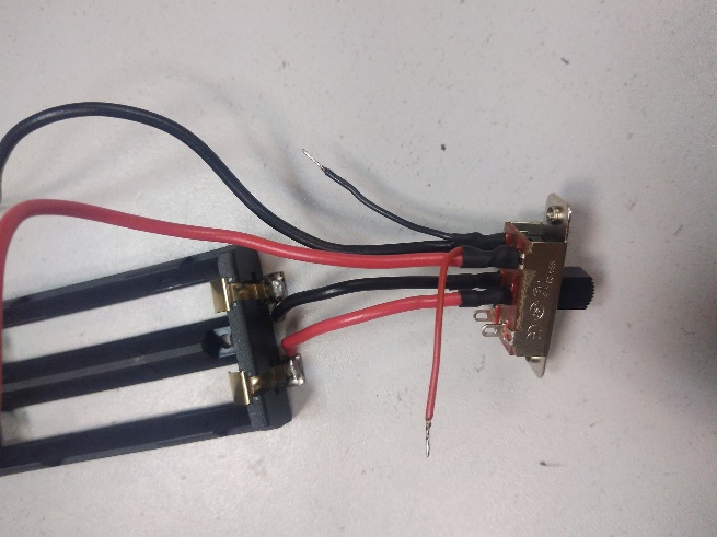 |
The length of the AWG24 wires is approximately the same as the wires going from the switch [S1] to the battery holder terminals. The length of the AWG18 wires is selected based on the distance from the edge of the case to the location inside the DC-DC module case.
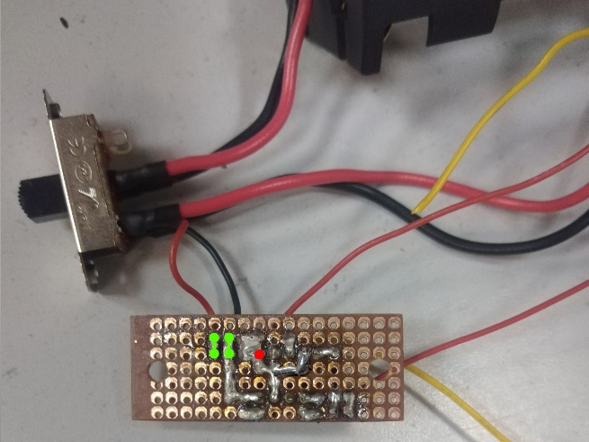
Solder the AWG24 wires coming from the switch [S1] to the voltage regulator [U1] on the PWM generator board. Connect the red wire to the ‘IN’ terminal, the black wire to the ‘GND’ terminal.
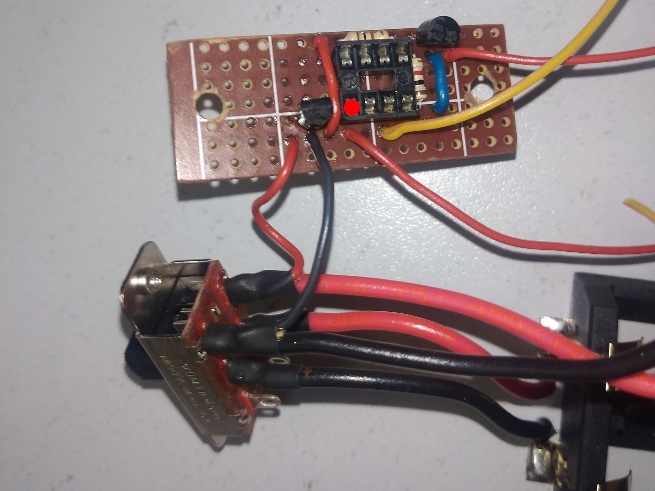 |  |
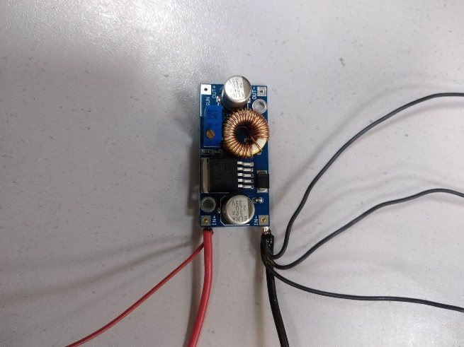
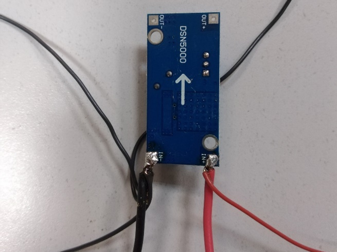
Solder the wires to the DC-DC module. The red AWG18 wire coming from the switch [S1] and another red AWG24 wire are soldered to the ‘IN+’ terminal. The black AWG18 wire coming from the switch [S1] and three more AWG24 wires are soldered to the ‘IN-‘ terminal.
 |  |
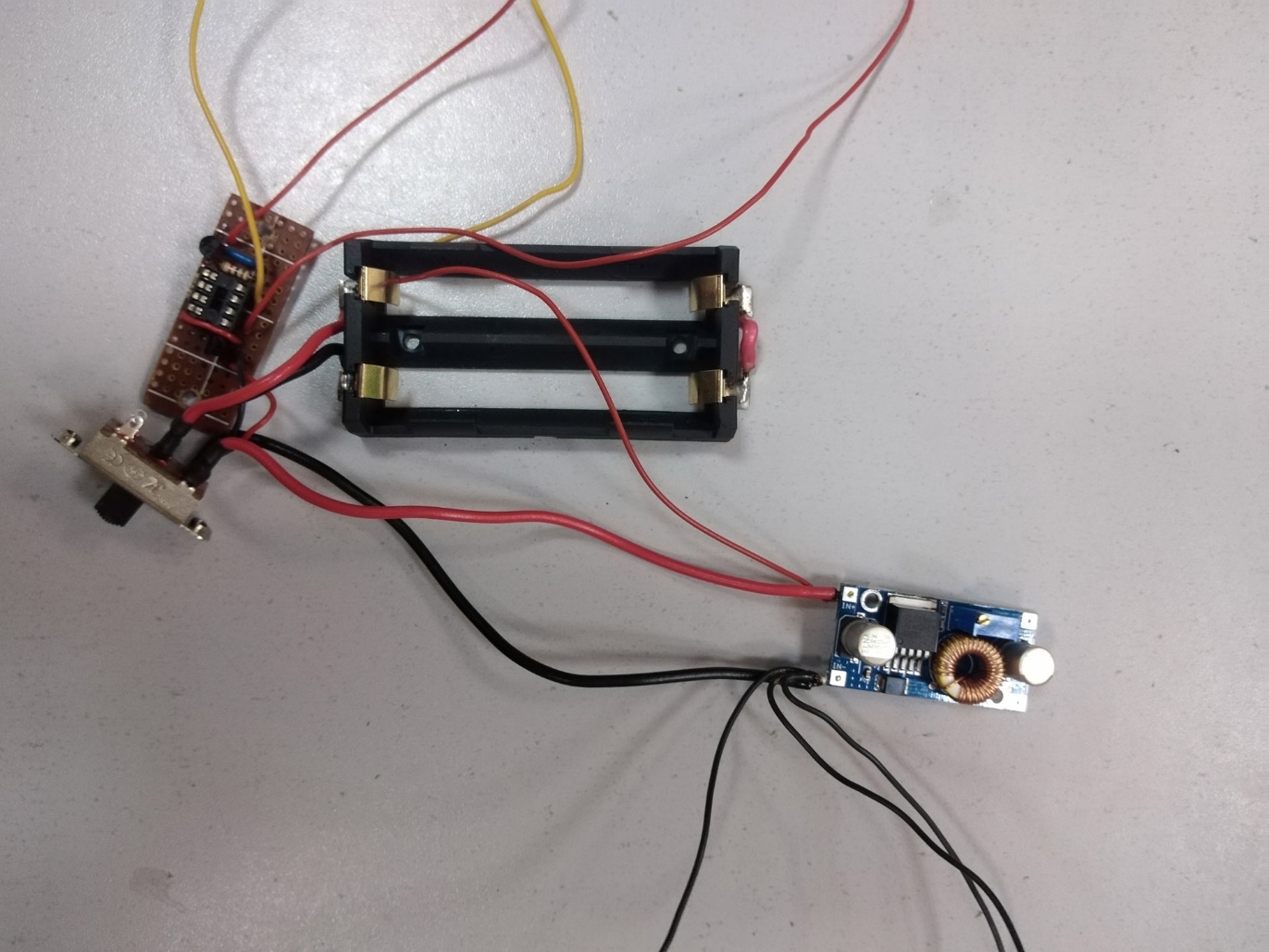 | |
The red AWG24 wire will be connected to the [S2] button, one black AWG24 wire will be connected to the cooling fans, the second to the MO1 board, and the third to the variable resistor [R1]. The length of the wires can be selected approximately based on the distance inside the case from the location of the DC-DC module to the location of the resistor [R1].
On the MO1 board, connect the ‘TTL-‘ contact to the ‘GND’ contact.
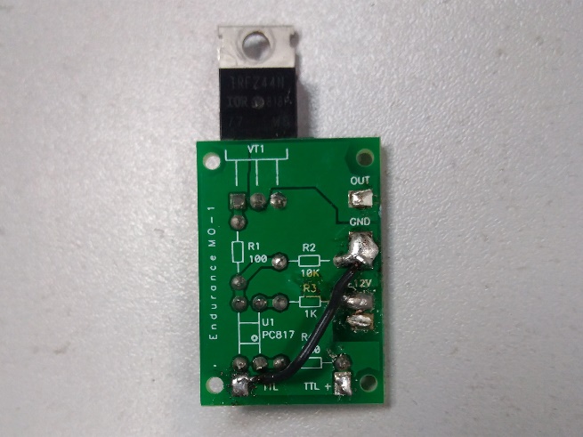 |
The control PWM signal is fed to the MO1 board via the ‘TTL+’ and ‘TTL-’ contacts. In the case where the PWM signal source and the MO1 board have different power sources (for example, the laser CNC machine operates from its own power supply, and the laser controlled by the MO1 board operates from its own), two wires go to the MO1 board. But since the PWM generator and the MO1 board have a common power source and the negative contact for all components is the same, the ‘TTL-’ contact is connected to the closer negative contact.
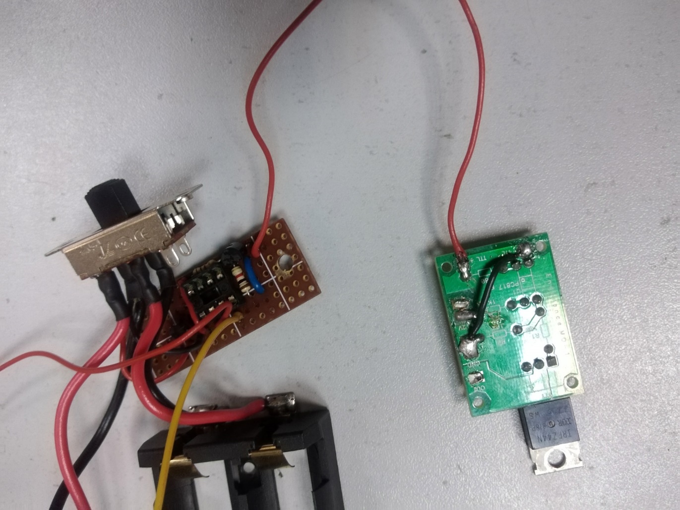
Solder the red wire connected in the PWM generator to the Emitter of the transistor [Q1] to the ‘TTL+’ contact on the MO1 board.
 |
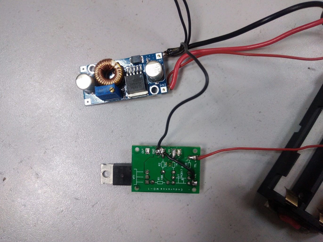
Solder the first black wire, connected to the ‘IN-‘ contact of the DC-DC module, to the ‘GND’ contact on the MO1 board.
 |
Solder the terminal to the red wire connected to the ‘IN+’ contact of the DC-DC module.
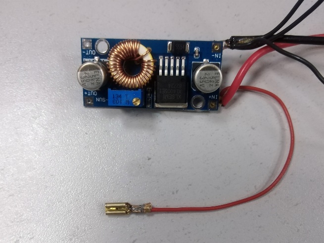 |
For convenience, this terminal will be designated as Terminal #1.
Solder two red AWG24 wires to the second terminal.
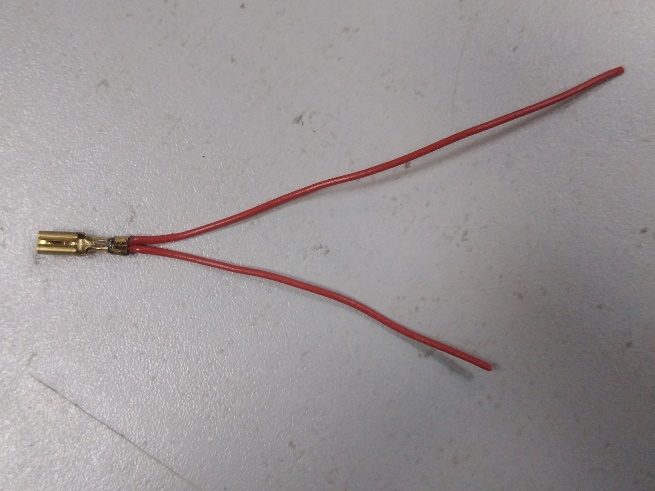 |
The terminal will be connected to the [S2] button. One wire will be connected to the MO1 board, the other to the cooling fans. For convenience, this terminal will be designated as Terminal #2.
Isolate the terminals using heat shrink tubing.
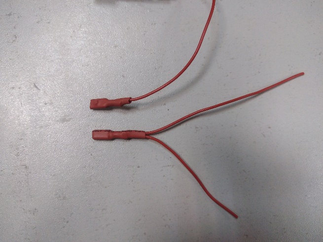 |
Solder one of the red wires coming from Terminal #2 to the ‘+12V’ contact on the MO1 board.
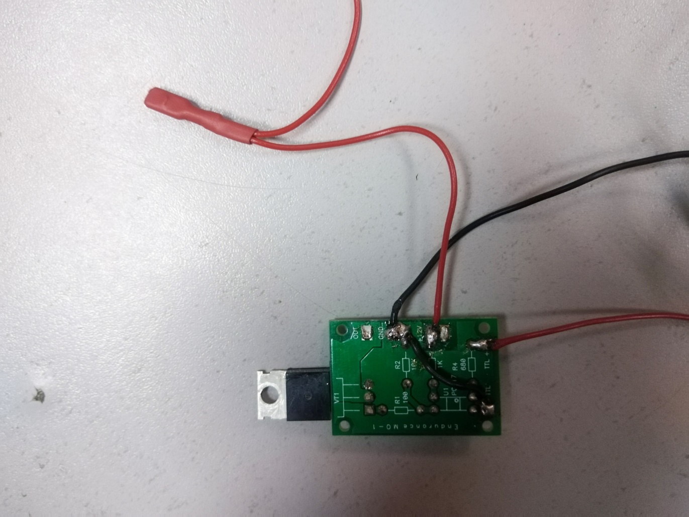 |
The variable resistor [R1] has a small protrusion on the side, which is designed to firmly fix the resistor to the mounting panel.
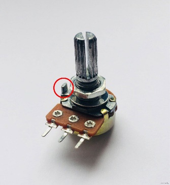 |
There is no hole for this protrusion in the pointer body. Therefore, this protrusion must be bitten off or filed down. In the following photos in this manual, this protrusion on the resistor is present, since it was filed down immediately before installing the resistor in the pointer. It is recommended to file down the protrusion in advance.
Solder the wires to the variable resistor [R1].
To the central contact – the yellow wire connected to Pin-3 of the microcontroller [U2] on the PWM generator board.
To the right contact – the red wire connected to Pin-1 of the microcontroller [U2] on the PWM generator board.
To the left contact – the black wire connected to the ‘IN-‘ contact of the DC-DC module.
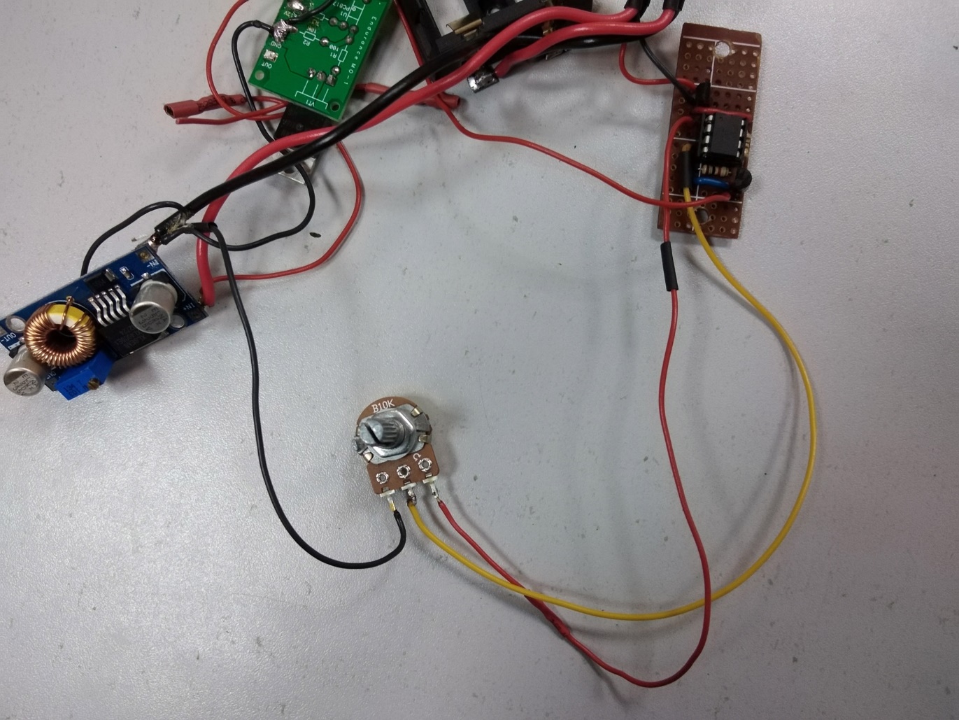 |
With this connection of wires, the laser power will increase when the resistor rod [R1] is rotated clockwise. If the wires on the left and right contacts of the resistor [R1] are swapped, the power will increase when the rod is rotated counterclockwise. The central contact of the resistor [R1] must be connected to Pin-3 of the microcontroller [U2].
Isolate the contacts of the resistor [R1] using heat-shrinkable tubing.
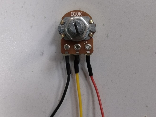 |
Install the microcontroller [U2] into the DIP socket.
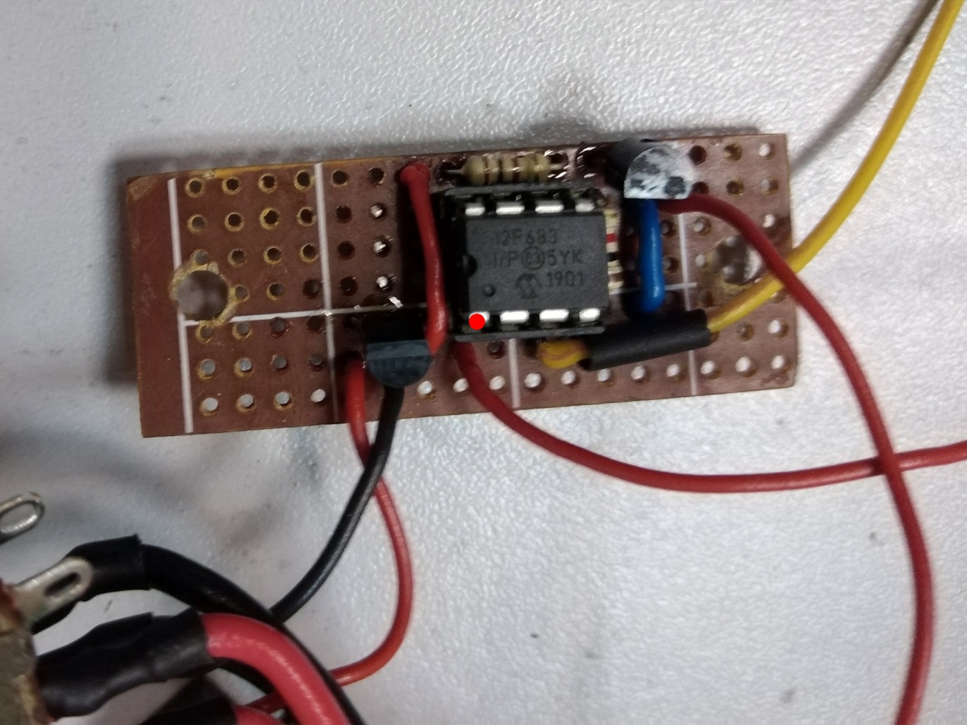 |
Installing the laser diode into the radiator.
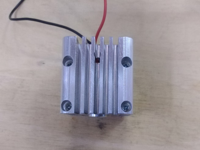
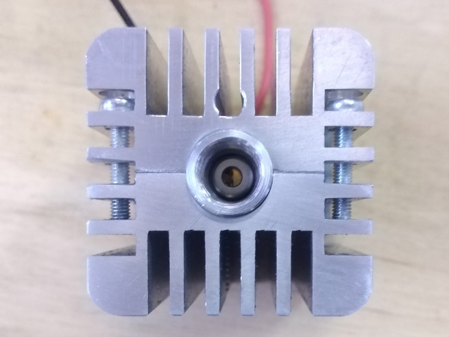
The radiator consists of two halves, between which the laser diode is installed. The laser diode is installed into the radiator so that its front part protrudes 1-1.5 mm from the radiator.
After installing the laser diode between them, the radiator halves are tightened together with four M3x16 screws with a hemispherical head.
To improve heat transfer between the laser diode housing and the radiator walls, a thin layer of thermal paste is applied to the laser diode housing (or radiator walls). During the process of tightening the radiator, excess thermal paste will be squeezed out, after which it will need to be removed with napkins, cotton swabs or something similar. When removing excess thermal paste, it is very important not to allow it to get inside the laser diode housing.
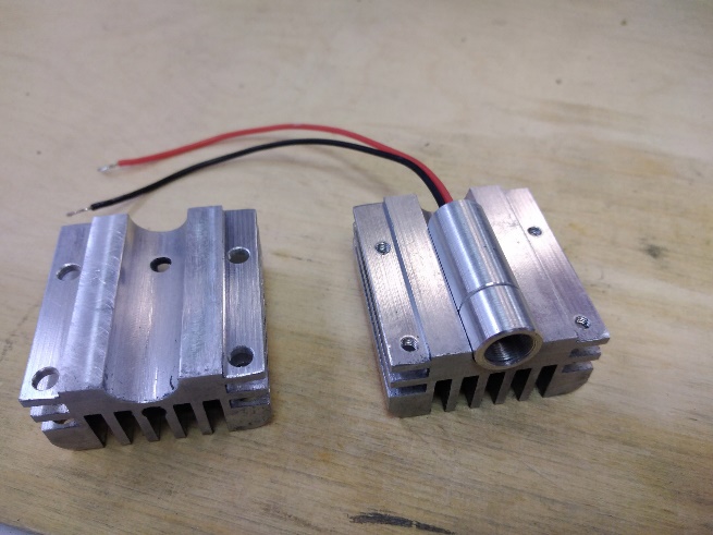 |  |
 | |
There are eight recesses on the inside of the fan mount. M3 nuts are installed in these recesses.
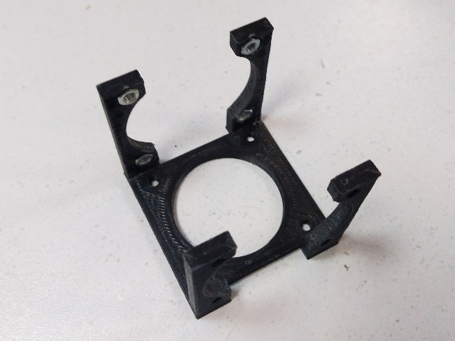
| 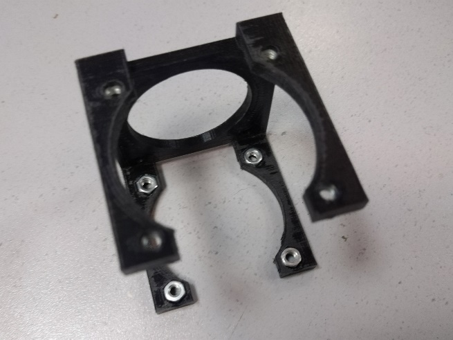 |
Install the fans on the mount.
The fans are attached using eight M3x16 hemispherical head screws. The wires exiting the fans should be located closer to the rear of the mount. Protective grilles are placed on top of the fans. The fan wires are led out through the hole in the rear of the mount.
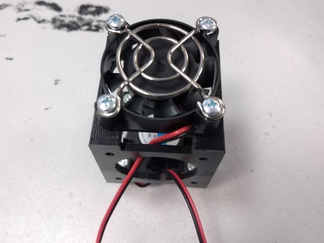 | 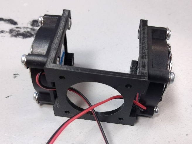 |
Pre-installation of the radiator in the fan mount.
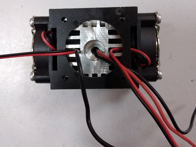
The radiator is installed inside the fan mount. The radiator should be positioned so that the longer fins of the radiator are opposite the fans. The fan wires are laid in the gaps between the fins and, together with the other wires, are brought out through the hole in the rear of the mount. The fan wires should not interfere with the tight fit of the rear side of the radiator to the mount.
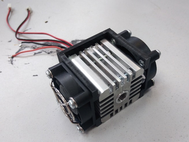 | 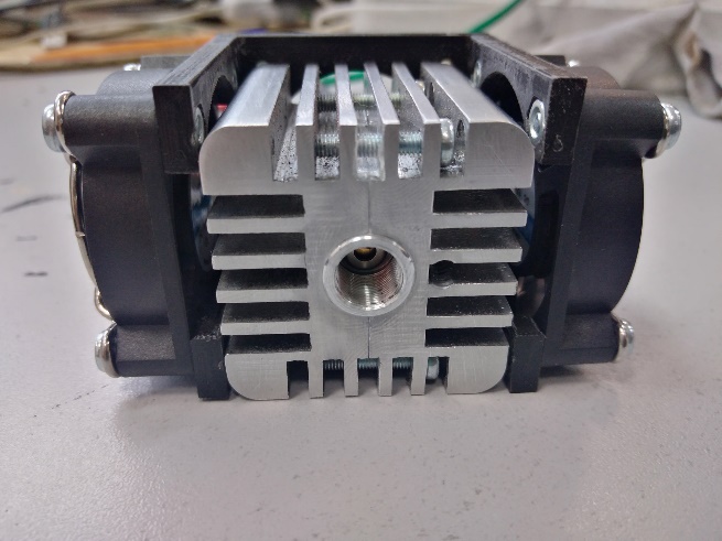 |
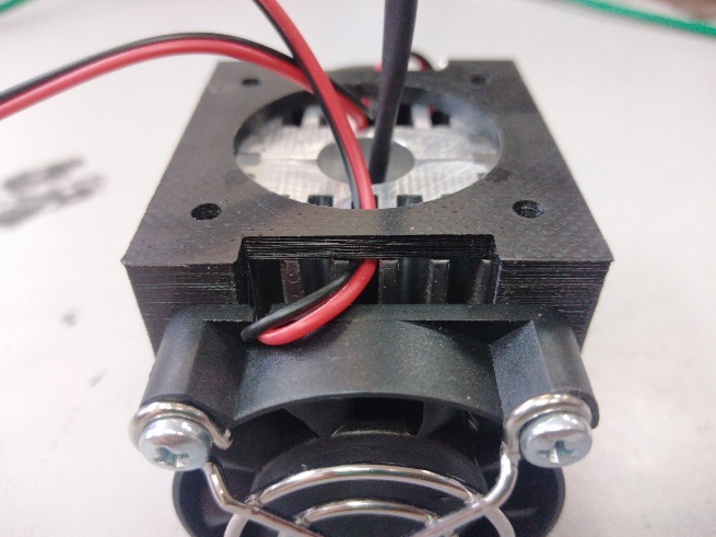 | 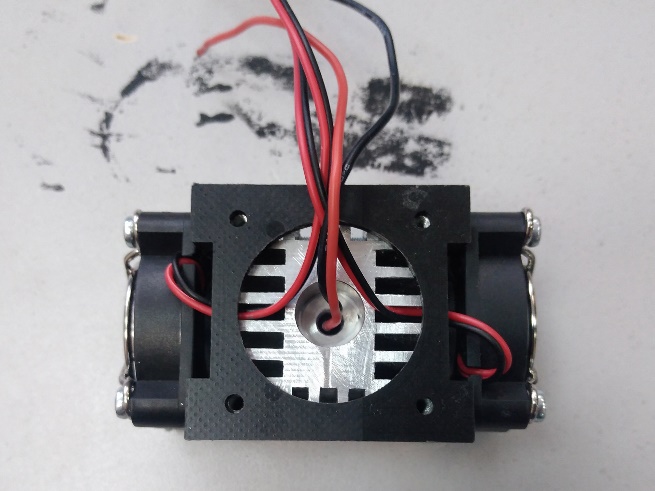 |
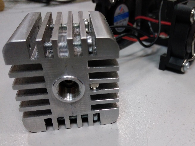
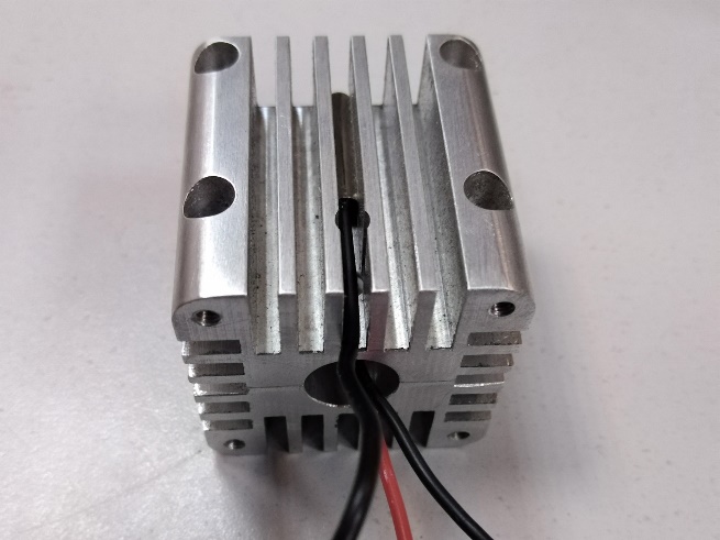
Before final installation, a thermal sensor is installed on the radiator.
The thermal sensor is passed through the hole in the front of the pointer body, then through the hole in the back of the fan mount. There is a small depression between the fins in the front of the radiator. The thermal sensor is installed in this depression. The wire coming out of the thermal sensor is placed in the gap between the fins and comes out the back of the radiator.
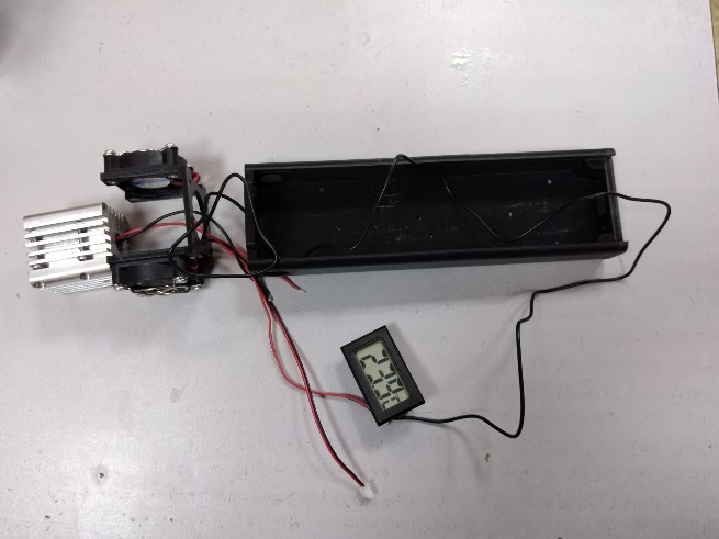 | 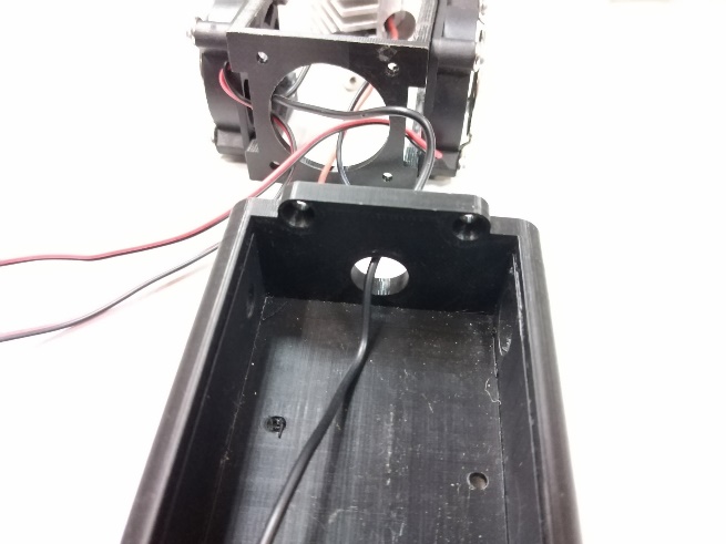 |
 |  |
 | |
Mounting the radiator and fans to the pointer body.
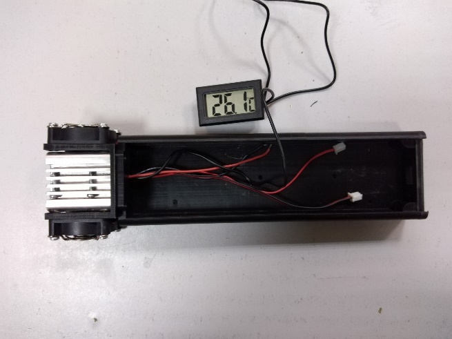
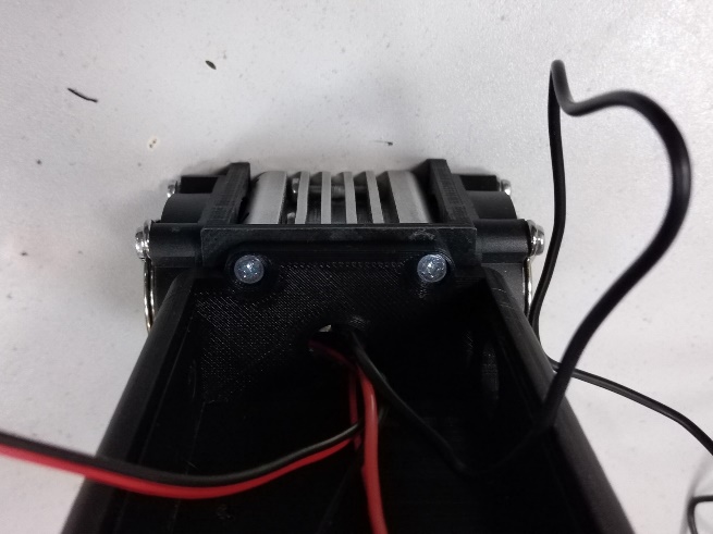
The radiator is pressed tightly against the fan mount. It is checked that the outgoing wires do not interfere with the fit of the radiator. All wires are brought out through the hole in the front part of the pointer body. The radiator with the fan mount is pressed against the pointer body. There are four holes with a cone-shaped recess in the front part of the pointer body. These holes must be aligned with the holes in the fan mount and the holes on the back of the radiator. Then four M3x12 countersunk screws are screwed into the holes to secure the radiator with fans to the pointer body.
 |  |
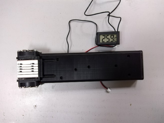 | 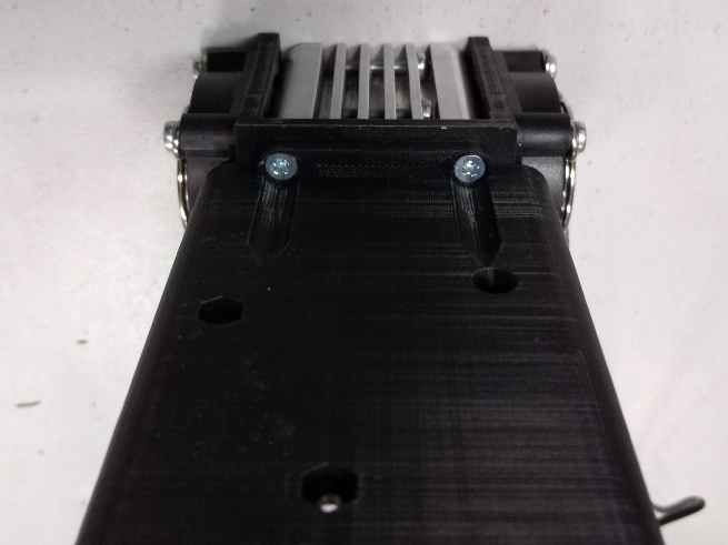 |
Before finally tightening the screws, it is necessary to tighten all the wires so that the wires do not create loops outside the pointer.
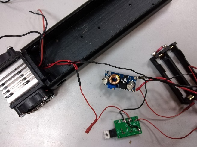
Solder the fan wires to the power wires. The black (minus) fan wires are soldered to the third black wire connected to the ‘IN-‘ contact of the DC-DC module. The red (positive) fan wires are soldered to the second red wire connected to Terminal #2. The soldered wire joints are insulated with heat shrink tubing.
 |
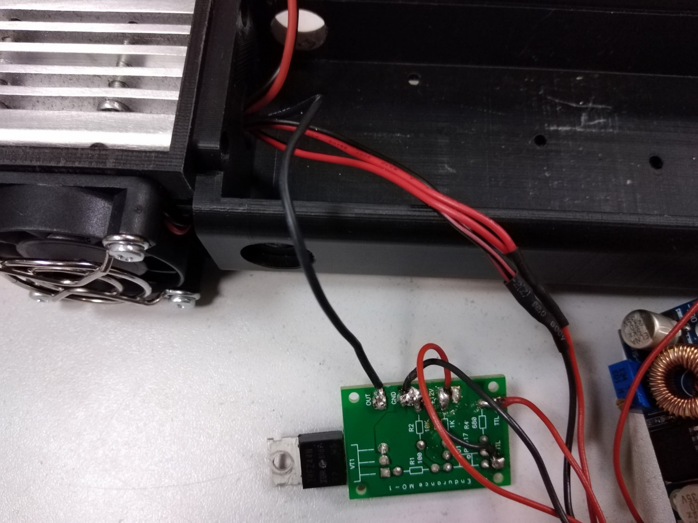
Solder the negative (black) wire of the laser diode to the ‘OUT’ contact on the MO1 board.
 |
Screw the switch [S1] to the back wall of the pointer body. For this, two M3x10 countersunk head screws are used.
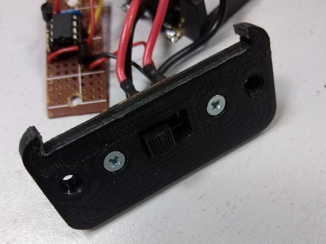 | 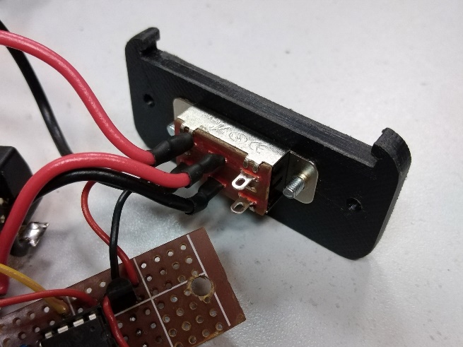 |
The switch [S1] is positioned so that when looking at the back wall of the case from the outside, the two unused contacts of the switch [S1] are located on the left side. The switch [S1] has three positions. The left and middle positions mean that the pointer is powered off. In the right position of the switch [S1], the pointer is on. Technically, the switch [S1] can be installed the other way around. But when assembling pointers from Endurance Lasers, it was decided that the switch [S1] is always installed as described above. This allows you to determine by its position whether the pointer is on or not.
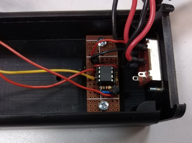
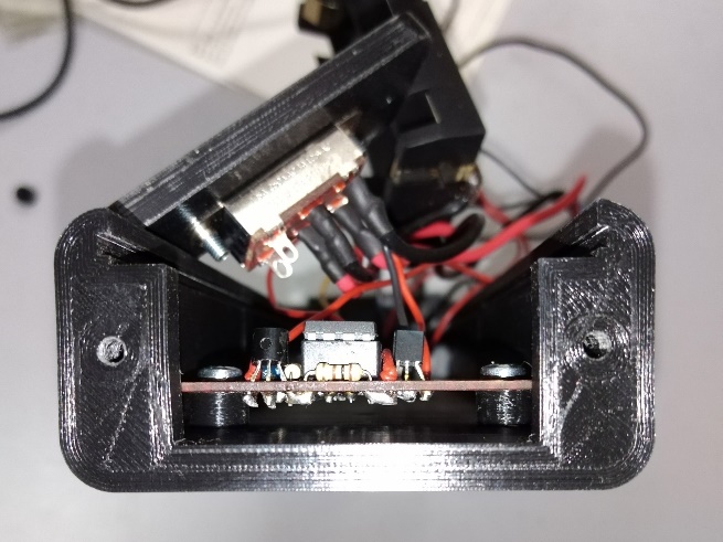
Install the PWM generator inside the pointer case. Install two M3 nuts in the recesses located closest to the edge of the back of the pointer case. Install two M3x10 screws with a hemispherical head in the mounting holes of the PWM generator. Then we put plastic bushings on the screws and install the screws in the mounting holes of the pointer case. Tighten the screws.
 |  |
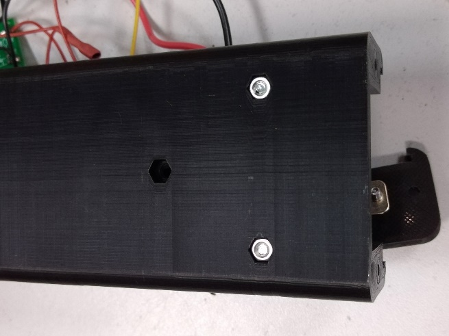 | 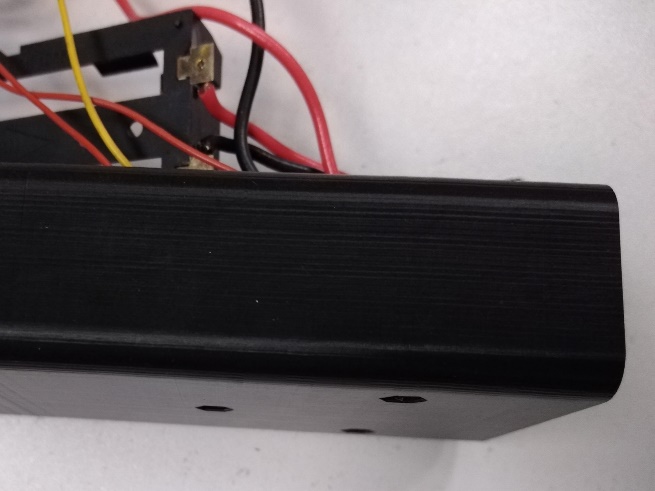 |
After tightening the screws, make sure that the screws and nuts do not protrude outside the pointer body. If the nuts protrude, then you need to unscrew the screws and check that the nuts are installed in the recesses correctly and there is no debris that prevents their installation in the recesses so that they do not protrude beyond the body. If the screws protrude, then they must be ground down to the desired length.
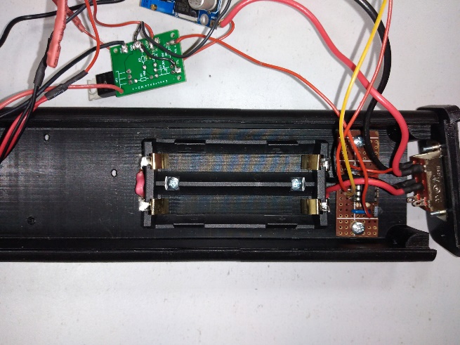
Install the battery holder inside the pointer body. Install two M3 nuts in the recesses in the pointer body, located after the recesses for the PWM generator. Using two M3x6 screws with a hemispherical head, screw the battery holder inside the pointer body.
 | 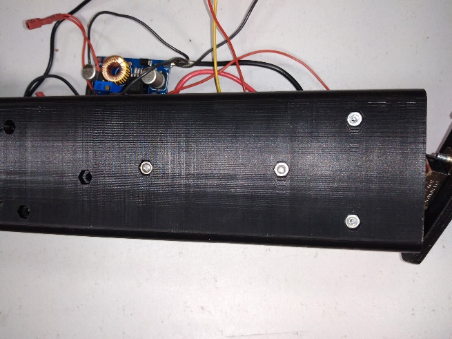 |
Install the MO1 board inside the pointer case. In the lower part of the pointer case, closer to the front edge, there is a hole with a cone-shaped recess. Install an M3x10 countersunk head screw into it. From the inside of the pointer case, we install the MO1 board on this screw through the mounting hole in the transistor. Position the MO1 board so that it is located along the pointer case and the transistor is closer to the front part of the case. Then install an insulating plastic sleeve on the screw and screw in an M3 nut from above.
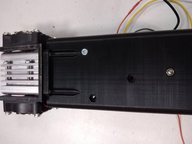 | 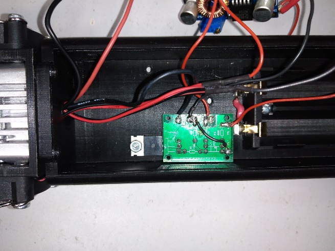 |
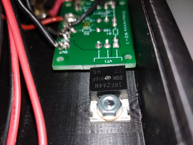 | |
Install the variable resistor [R1] into the pointer housing. The resistor [R1] is installed from inside the pointer housing into the hole located on the side of the MO1 board. From outside the housing, a washer is put on the resistor [R1] thread and the resistor is pressed with a nut.
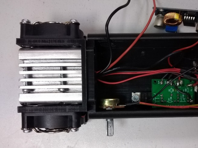 | 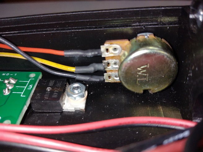 |
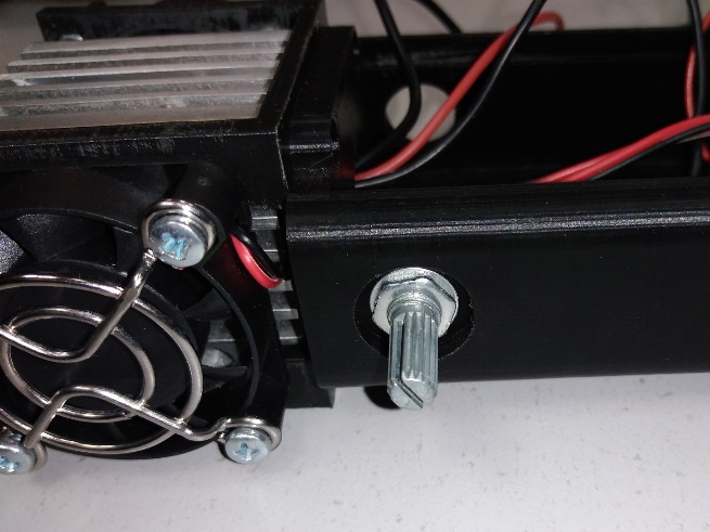 | |
Install the [S2] button into the pointer body. The button is installed into the hole located opposite the hole for the resistor [R1]. First, a nut from the [S2] button is put on the wires with terminals #1 and #2, then these wires are pushed through the hole in the pointer body, the terminals are put on the contacts of the [S2] button, the button is installed into the hole and pressed with a nut.
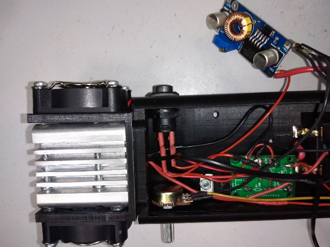 | 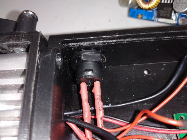 |
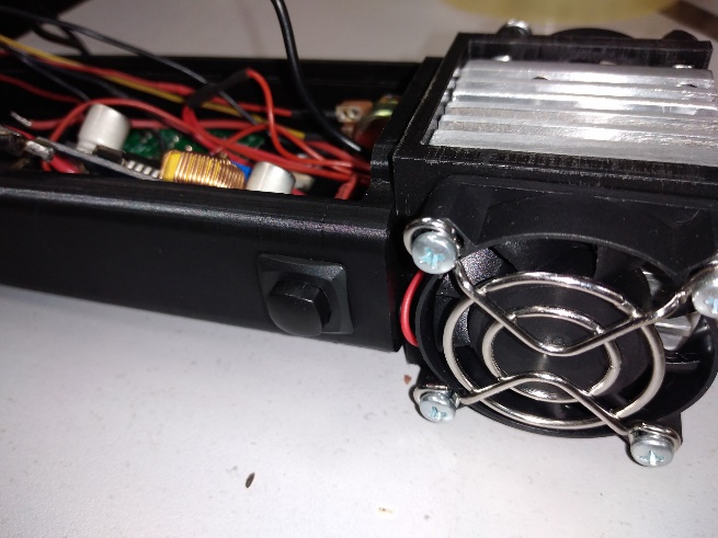 | |
Setting up the pointer
For a laser diode, the most important characteristic when setting it up is the current passing through it. The operating current of a laser diode is specified in its documentation. For Nichia NUBM44/47 laser diodes, the maximum operating current is 5A, but as experience with these laser diodes shows, the optimal operating current for them is 4.5A.
To measure current, Endurance Lasers uses a slightly modified tester.
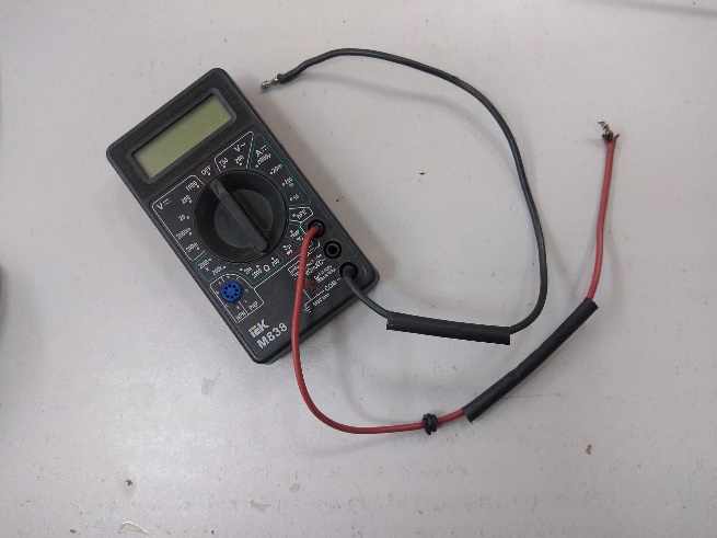 |
In it, thick wires are soldered into the probe connectors, which are soldered into the line on which the current needs to be measured. Compared to using regular probes, this option is more reliable.
Solder the Red wire of the tester to the ‘OUT+’ contact of the DC-DC module, the Black wire of the tester to the red (positive) wire of the laser diode.
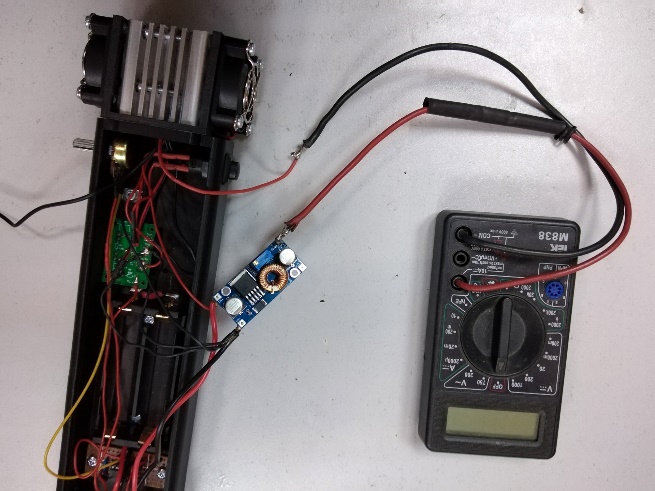 |
The tester wires can be soldered the other way around. This will not affect the current measurement in any way, only the tester will show the current with a “-” sign.
To supply power to the laser pointer, you can use 18650 batteries, which will power the pointer when it is fully assembled. But the batteries will discharge during the setup process and will need to be charged, which will take additional time.
Since the pointer’s electrical circuit is designed to operate from a constant voltage of 12 V, it is more convenient to use a power supply with an output constant voltage of 12 V and a maximum current of at least 4 A as a source during the setup process.
To power the pointer from the power supply, you need to make an appropriate adapter. For this, you will need a 12 V power connector and two AWG18 leads. On one side, the wires are connected to the power connector, on the other side, the wires are tinned and the tinned part is bent into a kind of bracket.
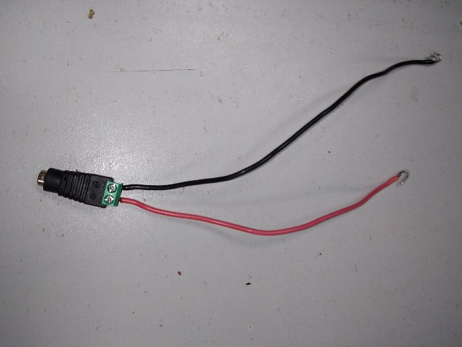 |
The brackets are inserted into the gaps between the battery terminals and the battery holder body.
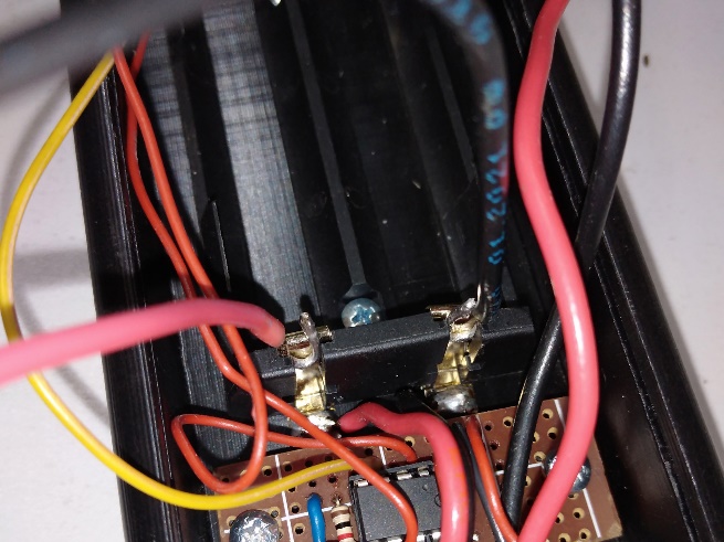 | 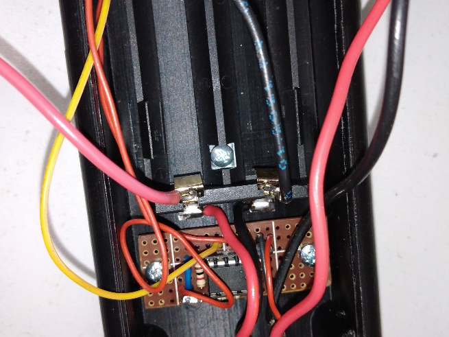 |
The DC-DC module has a trimmer resistor with an adjustment screw, which regulates the output voltage of the DC-DC module. Before starting the adjustment, you need to turn this screw counterclockwise by 20 turns using a screwdriver to set the minimum output voltage.
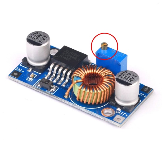 |
Before connecting the power supply to the pointer, you must do the following:
Set the switch [S1] to the far left position (the pointer is off);
Check that the button [S2] is in the “Off” position;
Turn the resistor rod [R1] counterclockwise until it stops (set the minimum – “zero” laser power).
Install a metal screen in front of the laser pointer at a distance of several centimeters. For convenience, you can stick a piece of masking tape on it to make it easier to control the appearance of the laser spot.
Connect the power supply to the pointer.
Set the tester to the 10A current measurement mode.
Turn the switch [S1] to the far right position.
Turn on the button [S2]. The fans on the pointer should start rotating.
Turn the resistor rod [R1] clockwise until it stops.
Check the tester readings. Technically, the laser pointer should turn on at maximum power, but the DC-DC module is currently set to a minimum output voltage of ~1.2V. This voltage is not enough to turn on the laser diode that is usually used in the pointer (the turn-on voltage of the Nichia NUBM44/47 laser diode is ~3.5V). Therefore, the tester readings should be 0A.
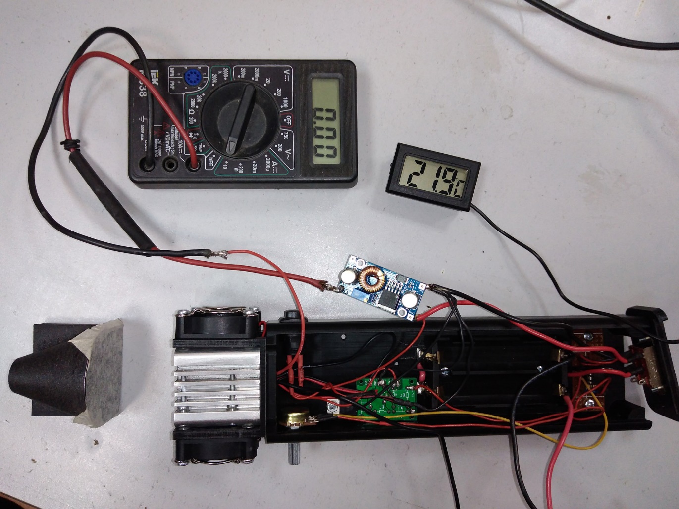 |
In this photo, the [S2] button is off, but if the DC-DC module is set to the minimum output voltage, the result should be the same when the button is on.
Carefully start turning the adjustment screw on the DC-DC module clockwise. After a few turns, the tester will start showing a small current of tenths of an ampere. Continue turning the screw – a faintly glowing blue circle will appear on the screen in front of the pointer. Continue turning the screw. When the current value approaches 1A, a bright rectangle will appear on the screen inside the circle. This means that the laser diode has turned on and is currently operating at its minimum power.
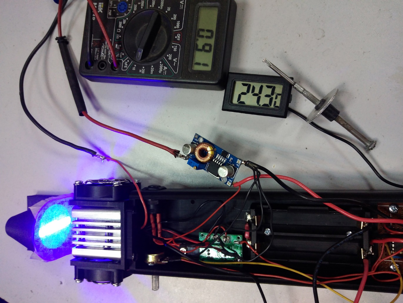 |
In this photo, you can see that the laser diode turned on at a current of ~0.9A.
Turn off the [S2] button. Set the laser power to the “zero” position with the resistor [R1].
To measure the output optical power of the laser diode. Its beam must be focused to obtain a smaller spot at the output. For this, we use the G2 lens.
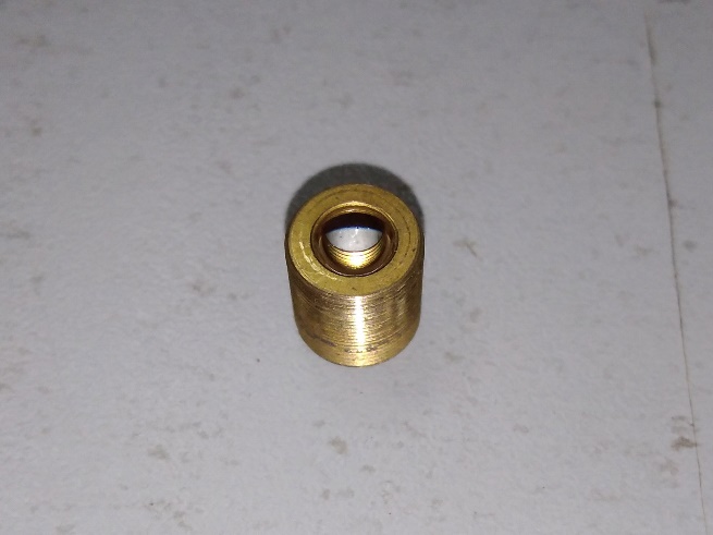 | 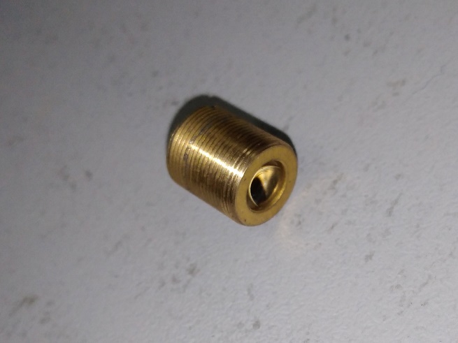 |
The lens is screwed into the laser diode so that two marks “under the screwdriver” on the lens body remain on the outside. The lens is screwed in until it stops, but there is a possibility of contact between the lens itself and the protective glass of the laser diode, which should not be allowed. Therefore, after screwing the lens in, it is unscrewed back half a turn.
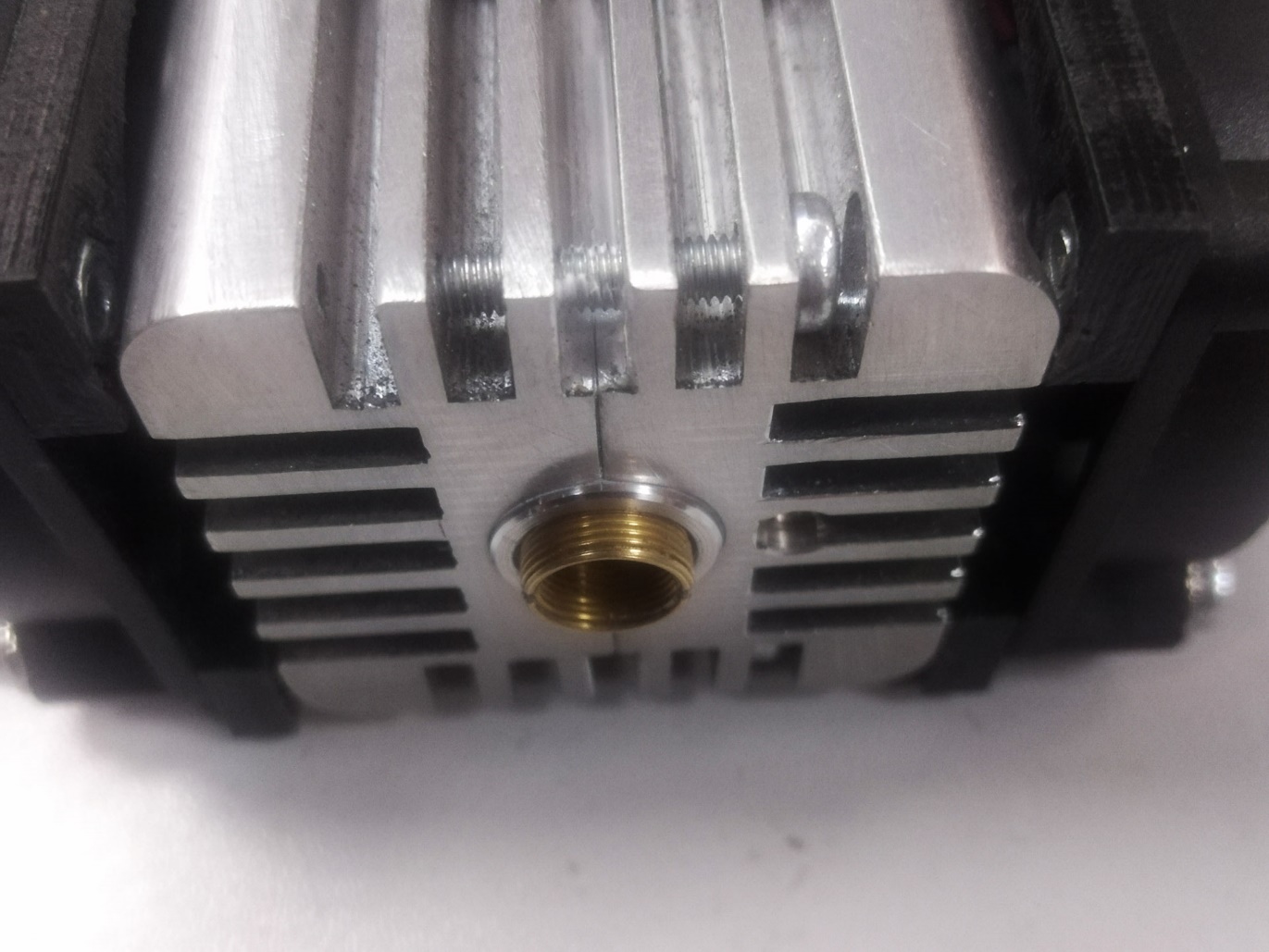 |
With further adjustment, the laser power will increase. As a result, the laser spot will be much brighter. To prevent this from interfering with further adjustment, and also to prevent the laser spot from accidentally hitting any non-metallic surface (and burning through anything), a light trap is put on the lens. Alternatively, you can put a metal screen (but without the tape glued to it) as close to the lens as possible.
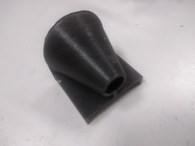 | 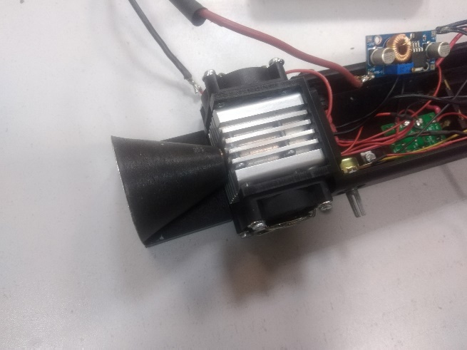 |
The light trap is a plastic cone, one end of which is put on the lens, and the other end is covered with an aluminum plate.
Next, in addition to measuring the current, you will need to measure the voltage supplied to the laser diode. For this, you will need a second tester. Set the tester to the DC voltage measurement mode of 9-12V. Using a crocodile clip, attach one tester probe (red) to the soldering point of the red (positive) wire of the laser diode and the black wire of the first tester. With the second probe (black), carefully touch the ‘OUT’ contact on the MO1 board.
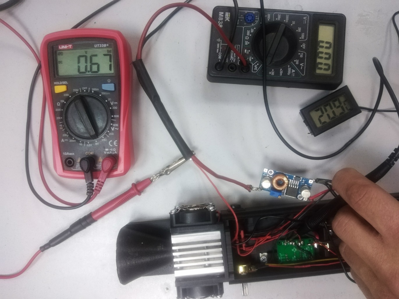 |
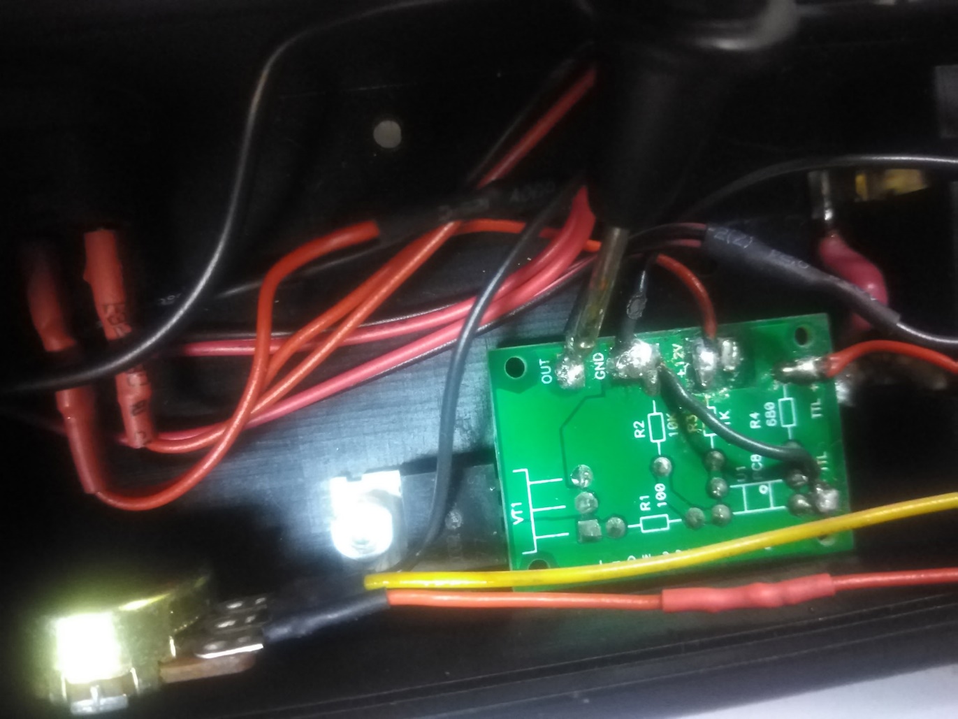 |
As you can see from the photo, the [S1] button is off, but the tester shows the voltage on the laser diode ~0.7V. This is due to the fact that the MO1 board controls the laser diode’s switching on via its negative wire. The positive wire is always connected to the positive output of the DC-DC module. Therefore, there is always a small voltage on the laser diode.
Turn on the [S1] button, set the laser power to maximum with the resistor [R1], and see what voltage the tester shows.
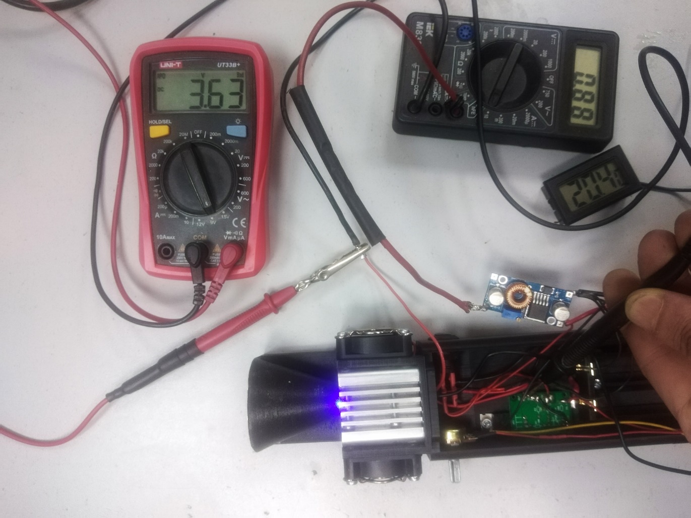 |
The voltage on the laser diode is 3.63V. This information is not important and is only needed for a general understanding of what voltage is currently on the laser diode.
Begin to turn the DC-DC module adjustment screw clockwise, increasing the voltage on the laser diode. The screw must be turned very slowly and carefully, because:
- The dependence of the current growth on the voltage growth is nonlinear. Conventionally speaking, the voltage will increase by 0.2V, and the current will increase by 0.5A (and this dependence changes depending on the voltage value). Accordingly, a small turn of the screw can cause a greater increase in current than expected.
- The trimmer resistor is not ideal and it may have zones when turning the screw does not cause a change in voltage, and when the screw leaves this zone, the voltage will increase sharply by several tenths of a volt. Accordingly, a situation may arise when the screw is turned a little, but there is no change and there may be a desire to turn it even further and faster, which can cause a sharp jump in voltage growth. If the current was less than 4A before, then this is not critical, but if the current is already approaching 4.5A, then a sharp and excessive turn of the screw can cause a current increase to 5A and higher, and at such a current the diode can fail.
Also, during the setup process, it is necessary to monitor the temperature of the laser diode, which is shown by the digital thermometer. The temperature should not exceed 40°C. If the thermometer shows a temperature close to this value, the setup should be stopped and the laser diode should be allowed to cool down to room temperature. If you turn off the [S2] button, the laser diode will turn off, but the cooling fans will also turn off (unfortunately, they cannot be kept on all the time, because the batteries will discharge even faster). Therefore, in order for the laser diode to cool down faster, the resistor [R1] reduces the laser power to “zero”. Formally, the laser diode remains on, but the PWM generator does not generate a PWM signal (or rather, it does, but with a duty cycle of 0%) and the MO1 board does not turn on the laser diode.
As a result, it is necessary to adjust the output voltage of the DC-DC module so that the current on the laser diode is 4.4-4.5A.
There is no need to constantly measure the voltage during the setup process. It is enough to check it periodically.
According to the results of the preliminary setup: the voltage on the laser diode is 4.42 V, the current is ~ 4.4 A. It is almost impossible to accurately adjust the current to hundredths of an ampere, because during operation the laser diode heats up, its resistance decreases and the current increases. Therefore, the current is calculated with an accuracy of 0.1 A.
Now it is necessary to measure the optical power of the laser diode.
For this, you will need a power meter. It is installed instead of the light trap. The power meter has a hole with a detector plate located inside. It is necessary to position the power meter so that it does not touch the radiator of the pointer, the G2 lens is located approximately in the center of the detector hole, goes slightly inside it, but does not touch the detector.
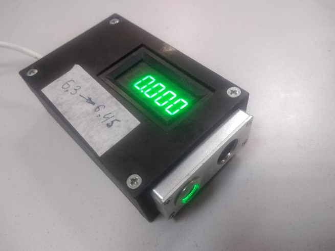 | 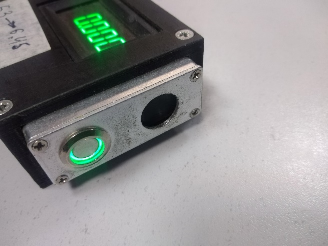 |
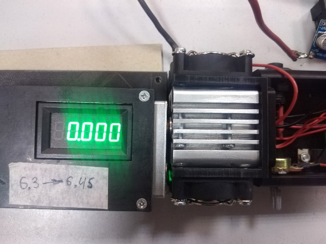 | 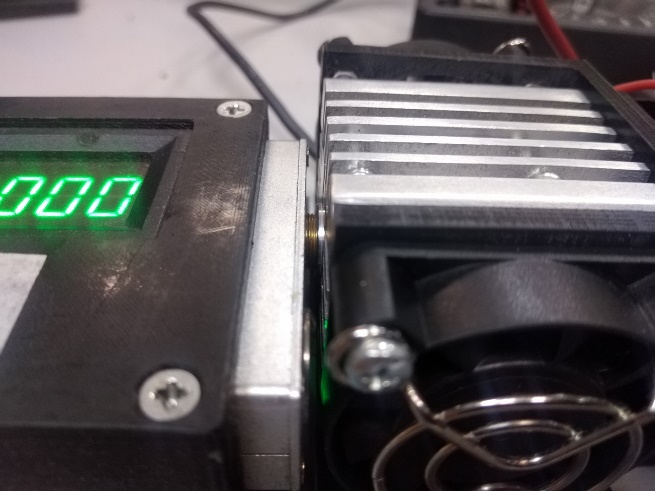 |
Power measurement is performed by heating the detector plate. Some of the air pumped by the fans onto the radiator may fall onto the detector plate and cool it, lowering the measurement result. To prevent this, the fans must be stopped for the duration of the measurement. The easiest way to do this is to stop the fans by placing an object in the fan grilles. This will stop their rotation – for example, a screw. This should be done when the fans are turned off.
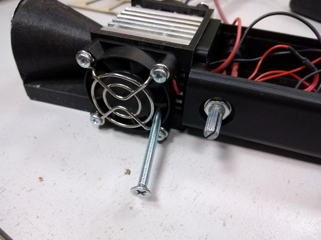 |
In the stopped state, the fans can be kept almost indefinitely – nothing will happen to them.
The procedure for measuring the laser power:
Install the power meter in front of the pointer;
Turn off the [S2] button (if it is on);
Turn off the fans;
Set the maximum laser power with the resistor [R1];
Turn on the [S2] button.
When measuring the readings, you need to very carefully monitor the temperature of the laser diode. Since the fans do not blow on the radiator, the laser diode heats up quite quickly.
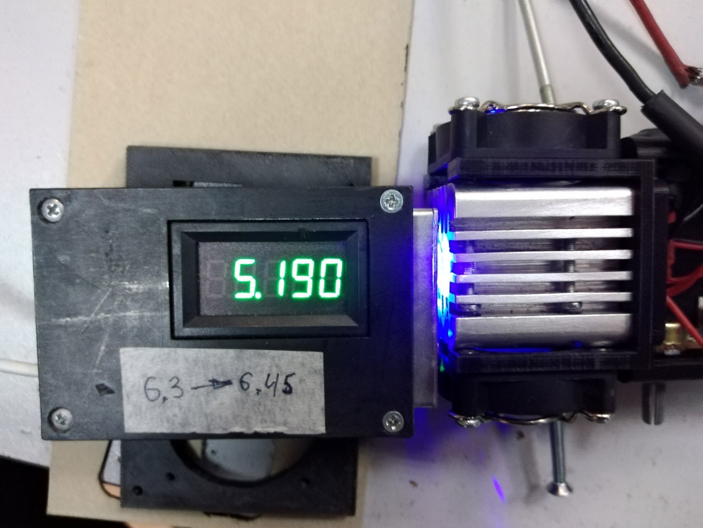 |
The power meter shows the laser diode power of 5.19 W. This particular power meter slightly overstates the readings by about 0.15 W.
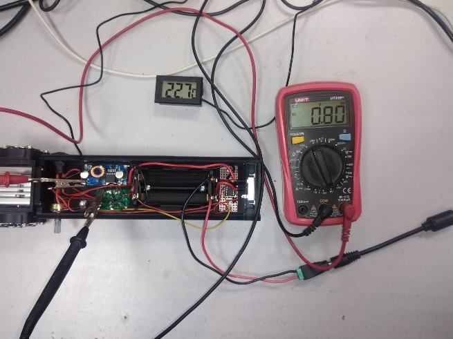
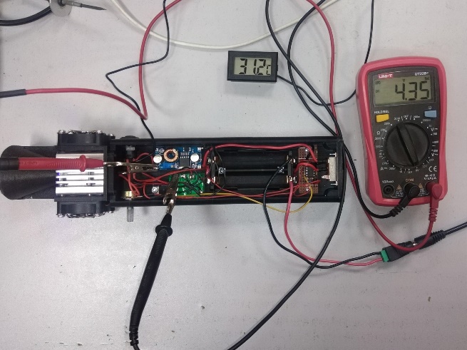
Based on this, we obtain the following characteristics: Voltage on the laser diode is 4.35 V, current is 4.4 A, power is 5 W.
After measuring the power with the resistor [R1], set the laser power to “zero” and wait for the laser diode to cool down. Turn off the button [S2]. Switch the switch [S1] to the far left position (turn off the pointer).
Unsolder the first tester from the DC-DC module and the laser diode. Solder the positive (red) wire of the laser diode to the ‘OUT+’ contact of the DC-DC module.
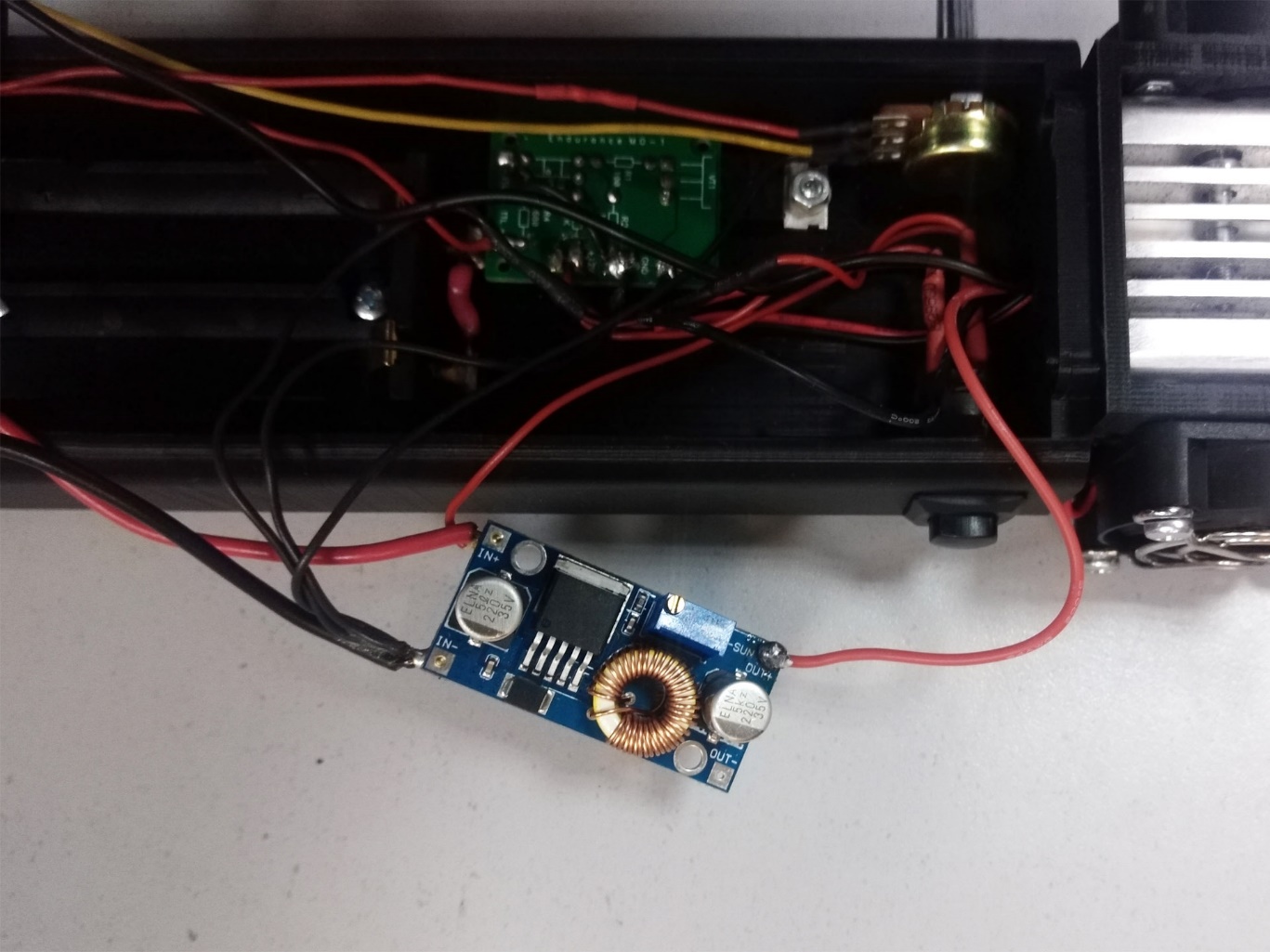 |
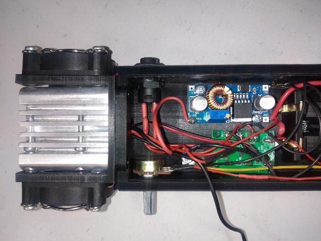
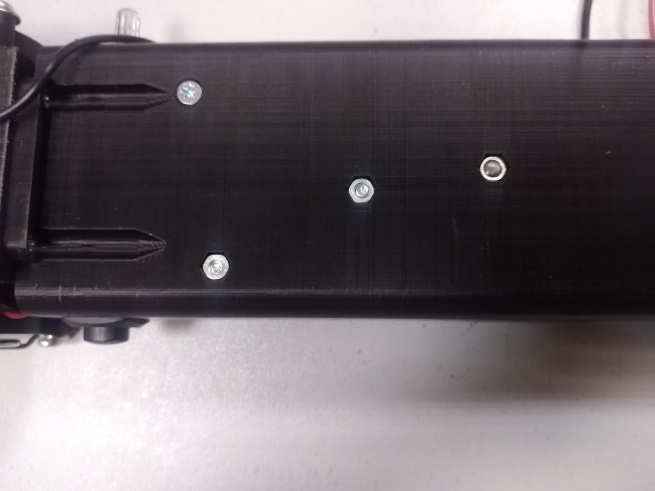
Install the DC-DC module inside the pointer body. Install two M3 nuts in the recesses located in the front part of the pointer body next to the [S2] button (the last two free recesses). Install two M3x10 screws with a hemispherical head in the mounting holes of the DC-DC module. Then install plastic bushings on the screws and install the screws in the mounting holes of the pointer body. Tighten the screws.
 |  |
The tester we used to measure the current on the laser diode, like any other electronic component, has a small resistance. Accordingly, when the voltage and current on the laser diode were adjusted, the voltage at the DC-DC module output was higher than on the laser diode. Now the laser diode is connected directly to the DC-DC module. If you turn on the pointer, the current on the laser diode will be higher. It is necessary to reduce the voltage at the DC-DC module output. To do this, turn the DC-DC module trimmer screw 3-5 turns counterclockwise (reduce the voltage). Install a light trap in front of the pointer. If you apply a little more solder to the contact pad when soldering the laser diode wires to the DC-DC module and the MO1 board, you can connect the tester probes equipped with crocodile clips to the resulting “drop”, which will make it easier to measure the voltage.
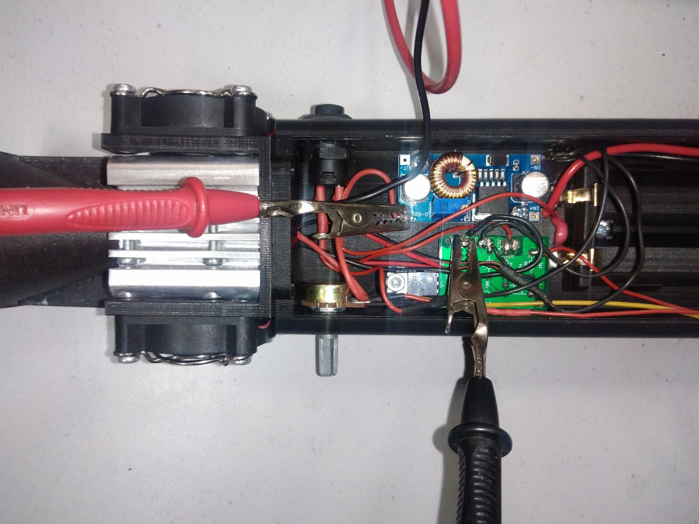 |
Turn on switch [S1]. Set resistor [R1] to maximum laser power. Turn on button [S2]. Set voltage at DC-DC module output to 4.35V with trimmer screw.
 |  |
After measuring the power with the resistor [R1], set the laser power to “zero” and wait for the laser diode to cool down. Turn off the button [S2]. Stop the fans. Install a power meter instead of the light trap and check its readings.
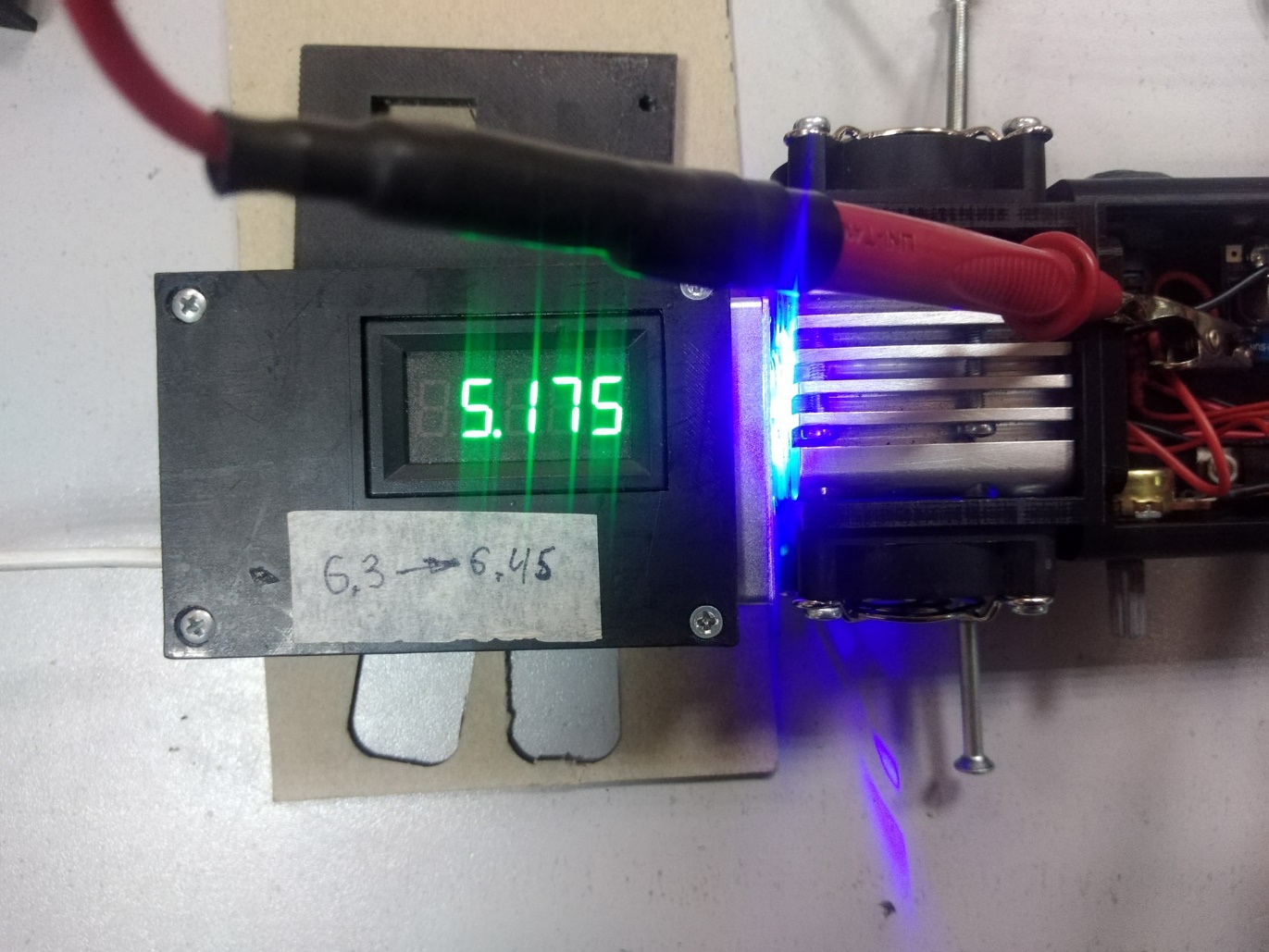 |
The readings are the same as in the previous measurement.
Reduce the laser power to “zero”, wait until the laser diode cools down. Turn off the button [S2], turn off the switch [S1]. Disconnect the adapter for the power supply from the battery holder.
Completing the assembly of the pointer
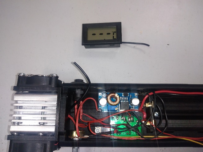
The wire from the thermometer to the temperature sensor is too long for a pointer. It needs to be shortened and made detachable for ease of installation.
Cut out most of the wire, leaving only the short ends and soldering two-pin connectors to them. Insulate the soldering points with heat shrink tubing.
 |  |
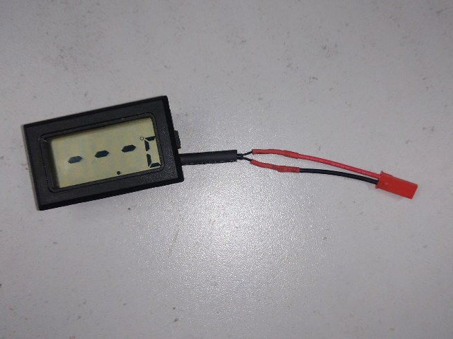 | 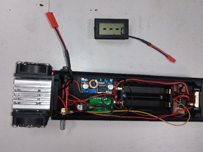 |
The wire connecting the temperature sensor to the thermometer consists of two thin wires in a common cable. The wires do not have polarity and are often the same color, so it does not matter which wire to solder to which connector wire. We usually solder the female connector to the thermometer, and the male connector to the temperature sensor, but this is also not of fundamental importance.
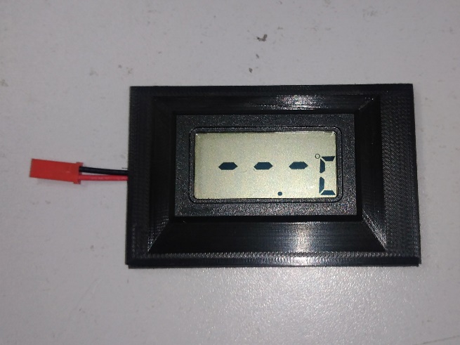
Install the thermometer in the front cover of the case. The thermometer has latches on both sides, with which it is fixed in the cover. There is a groove in the cover, into which you need to lay the wire coming from the thermometer. If you look at the cover from above, the wire should come out to the left of the thermometer.
 | 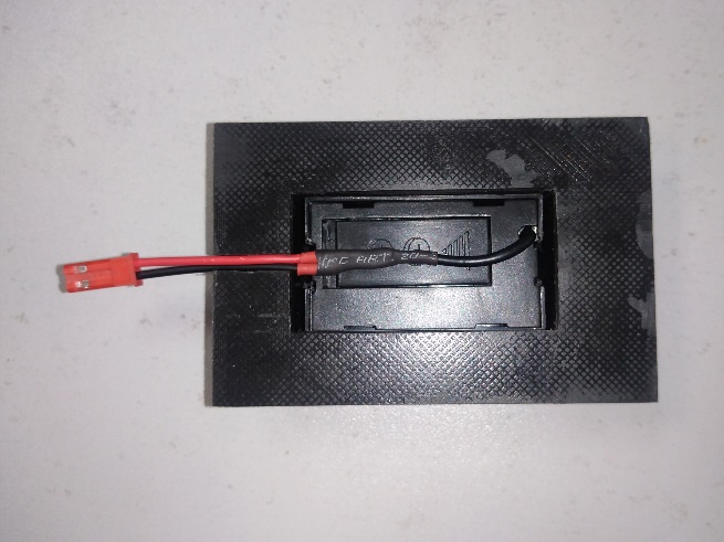 |
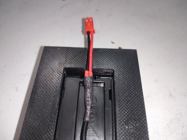 | |
Screw the back wall to the pointer body using two M3x15 countersunk head screws.
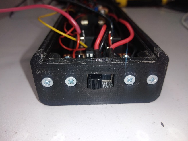 | 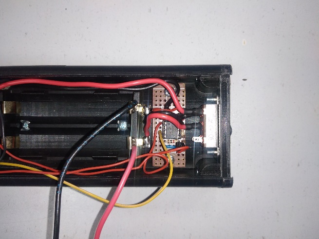 |
The screws are screwed into the through holes in the pointer body without using nuts. Since it is quite problematic to print M3 threads with PLA plastic, these holes are printed with a smaller diameter. Next, you need to clamp either a long M3 screw or a stud with an M3 thread in a screwdriver and cut threads in the holes at low speeds. The thread can also be cut using a tap, but it will be looser and less reliable due to the fact that PLA plastic is quite soft.
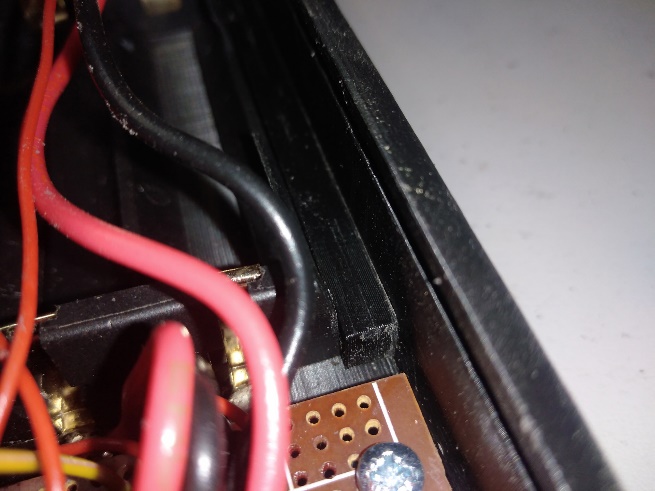
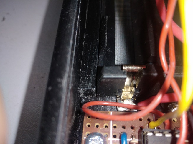
Since the battery holder is made of pressed plastic, it is quite fragile and when installing batteries in it (or removing batteries from it), its side wall may break off. To prevent this from happening, plastic rectangular gaskets must be installed between the battery holder and the walls of the pointer body.
 |  |
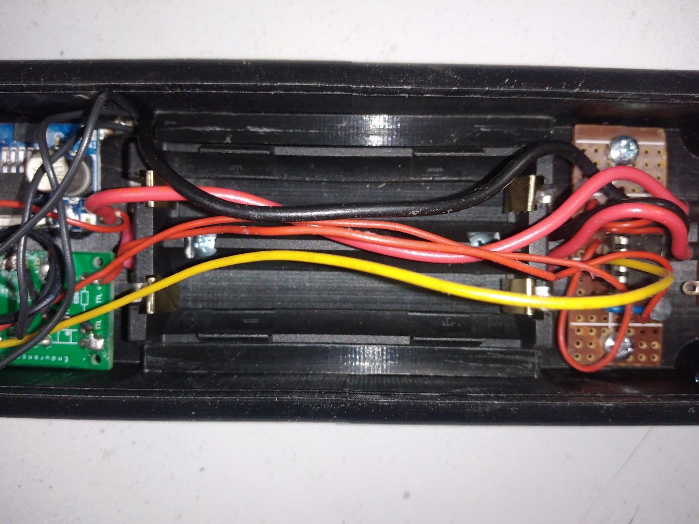 |
The gaskets should be installed tightly, but without applying excessive force. If necessary, reduce the thickness of the gaskets by filing them down.
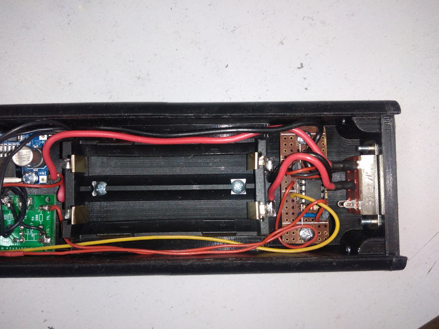
Lay the wires inside the pointer body so that they run along the walls and do not pass over the battery holder.
 |
Install the front cover with the thermometer into the pointer body. There are grooves in the back of the pointer body. The cover is inserted into them and pushed all the way into the front part of the body. After the front part of the cover covers half of the DC-DC module, the wire with the connector must be removed from the groove in the cover and connected to the connector of the temperature sensor. Then the wires are sunk into the pointer body and the cover with the thermometer is pushed in completely.
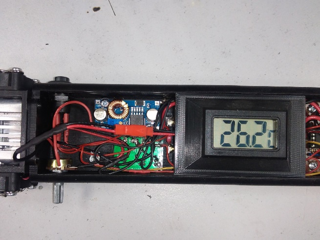 | 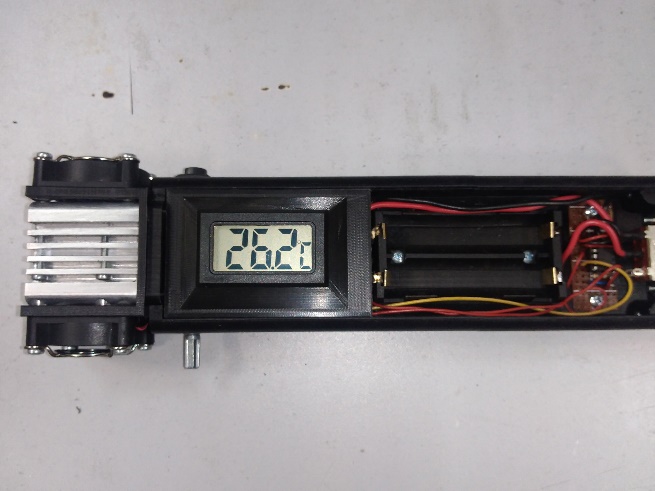 |
Assemble the back cover. Install two M3 nuts in the recesses on the bottom of the back cover. Install the retainer in the back of the cover. The retainer has a rectangular protrusion that should fit into a similar hole in the cover. Install the retainer cover on top of the retainer and screw it in place with two M3x12 countersunk head screws. There is a slot in the retainer. With its help, the retainer should rise and fall inside the back cover, while the retainer protrusion should protrude from the bottom of the cover, or go inside it.
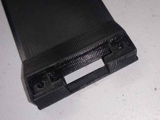 | 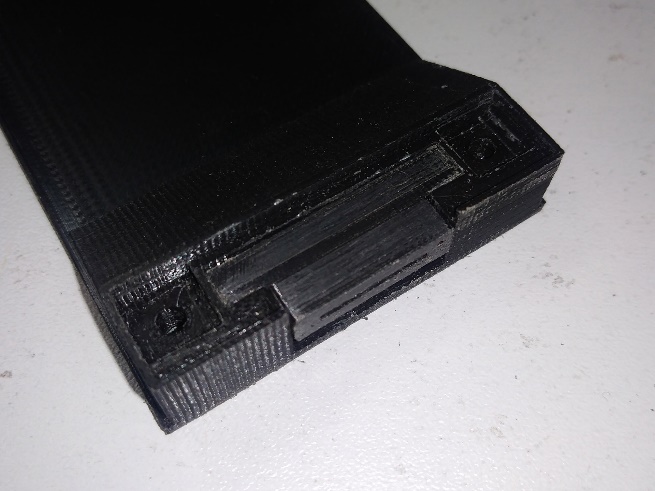 |
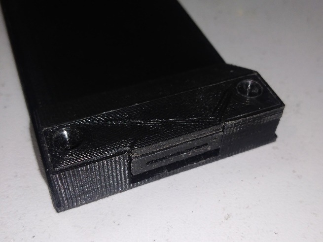 | 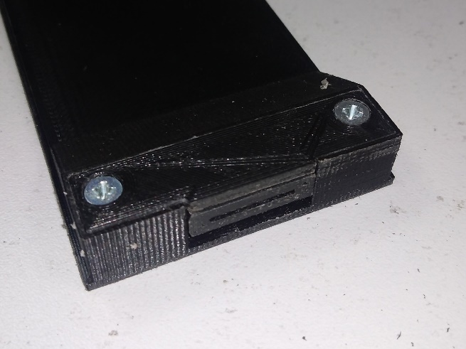 |
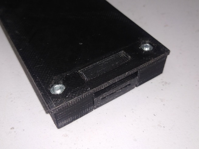 | 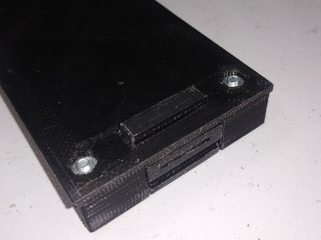 |
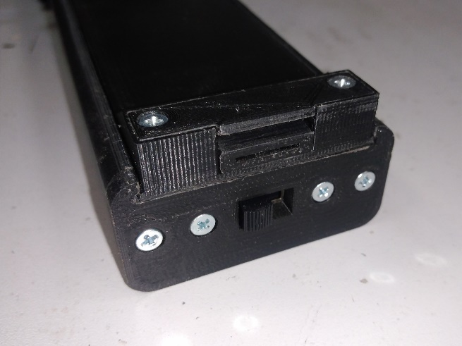
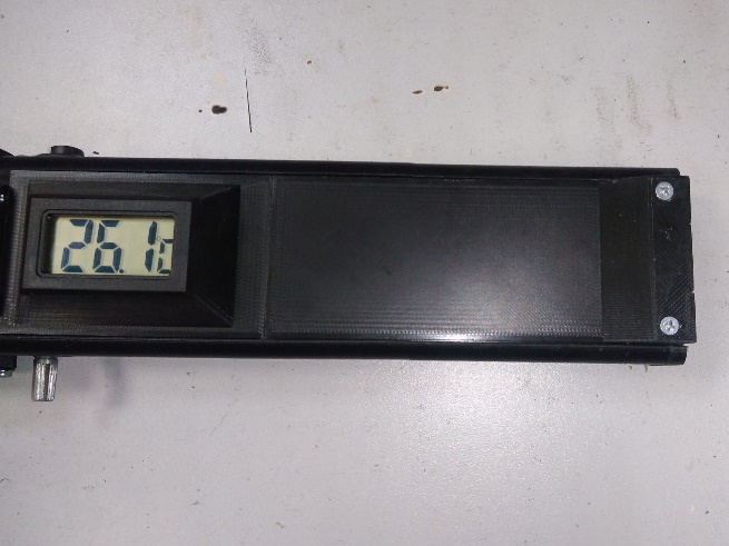
Install the back cover into the pointer body. Slide the back cover into the pointer body through the same slots as the front cover with the thermometer. Move the lock to the lower position so that the cover does not slip back.
 |  |
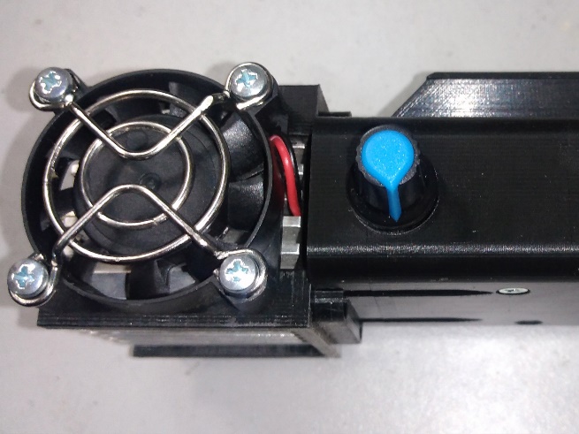
Install the potentiometer control handle on the variable resistor rod [R1].
 |
Unscrew the G2 lens from the laser diode and install the lens that comes with the laser diode.
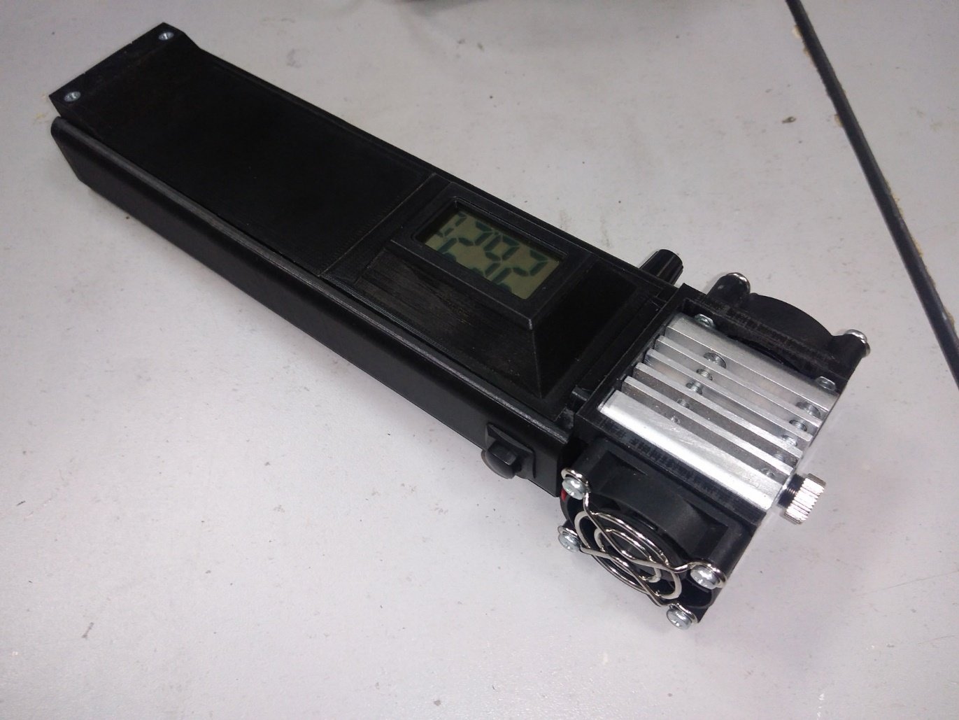 |
The laser pointer is ready to use – all that remains is to install the batteries.