
A professional chiller for a DPSS, Fiber, Co2 laser (Endurance Lasers LLC).
Chiller Product Description (Typhoon 90)
The chiller features
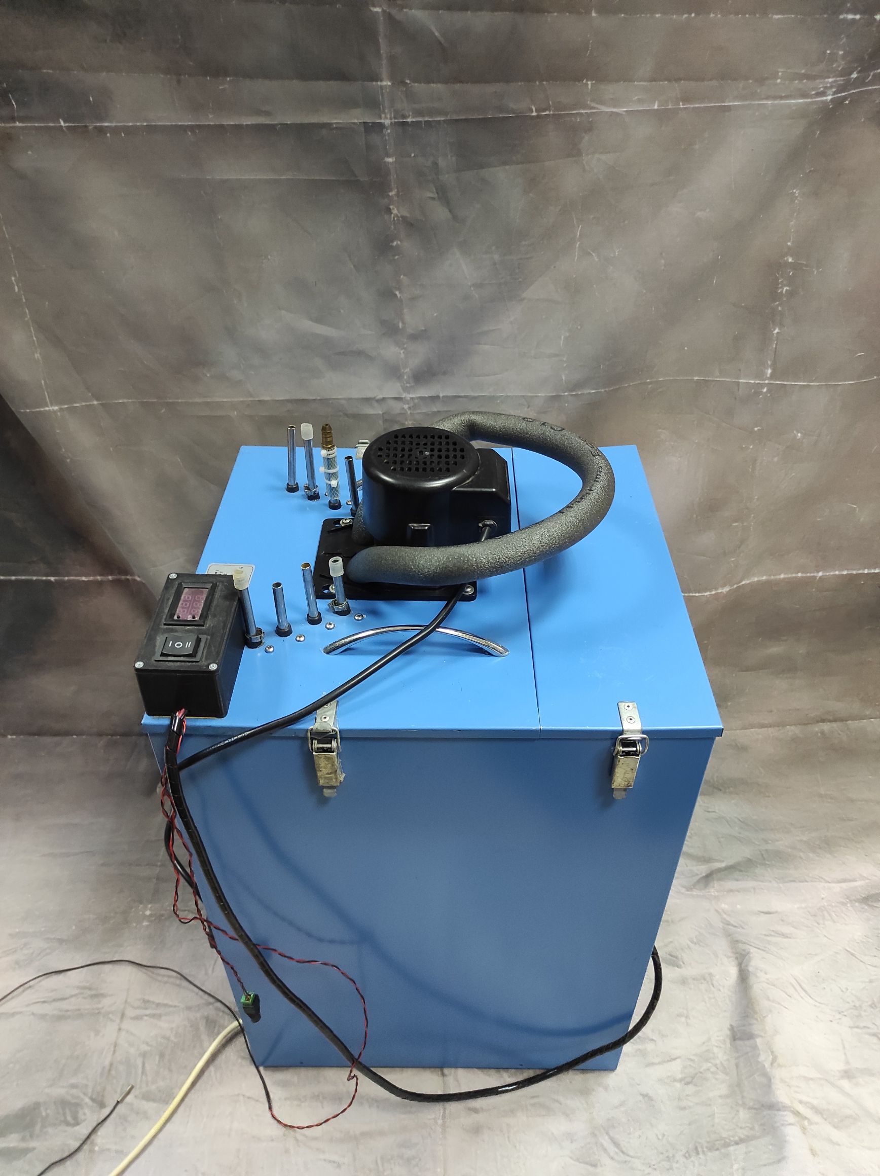
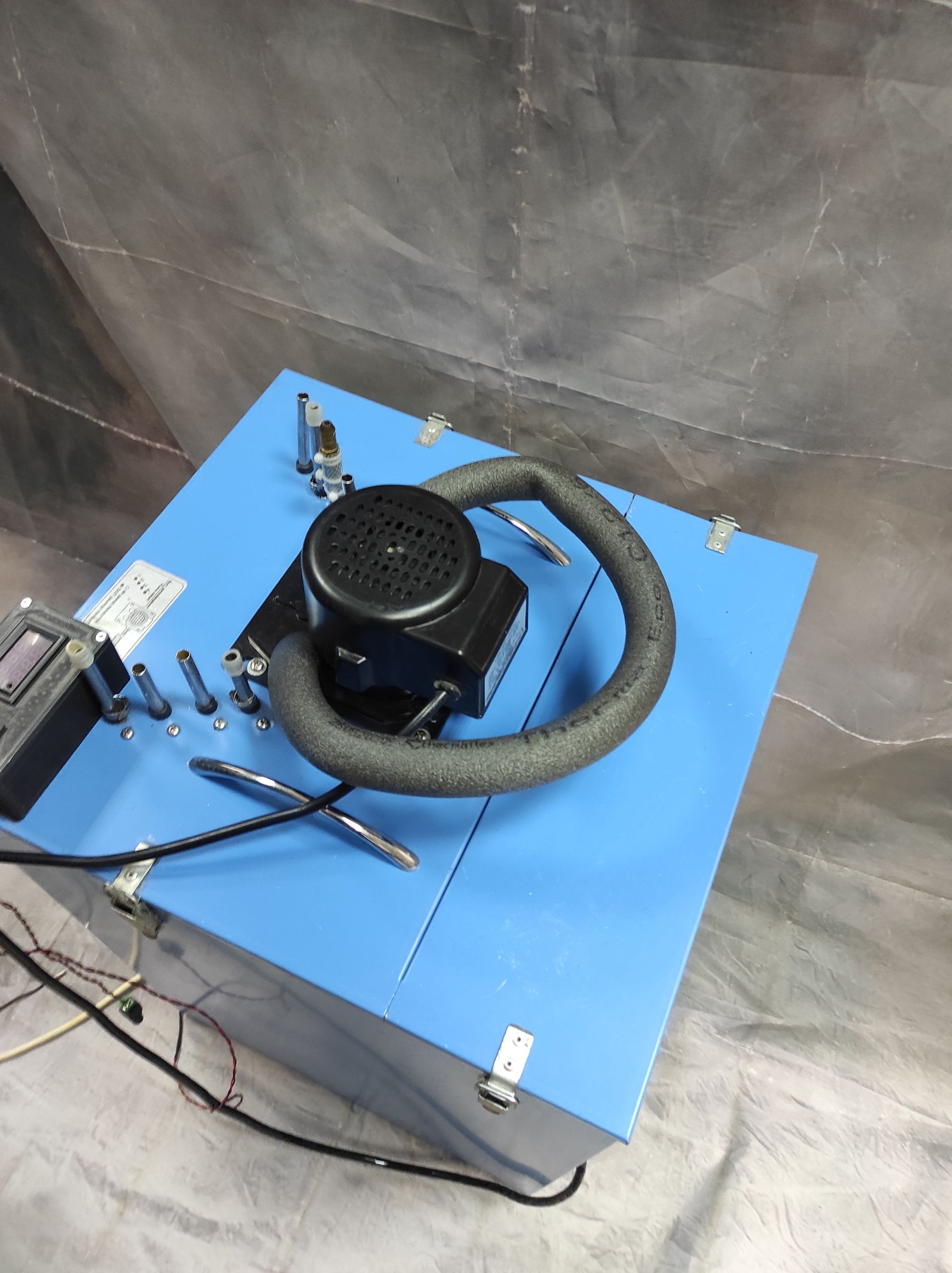
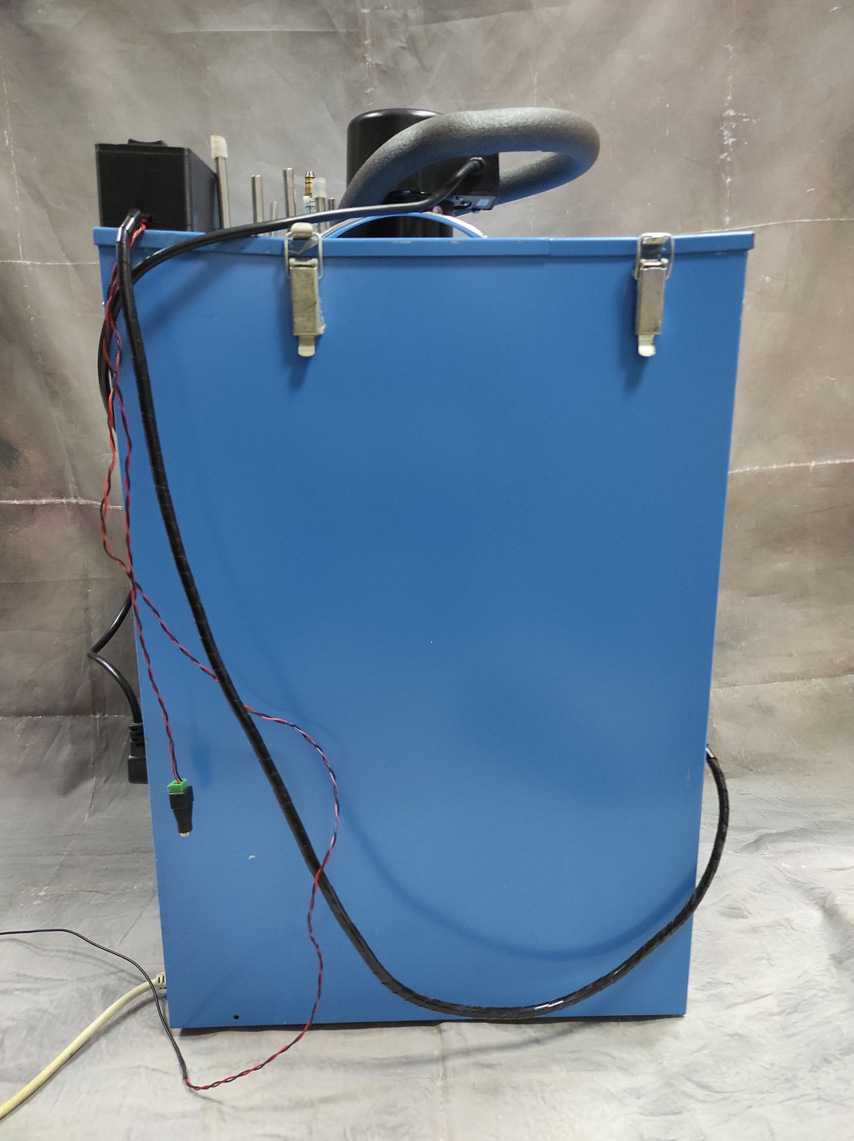
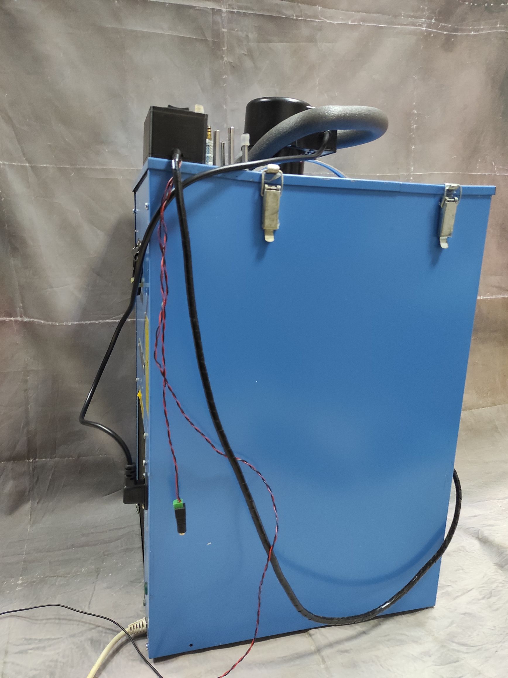
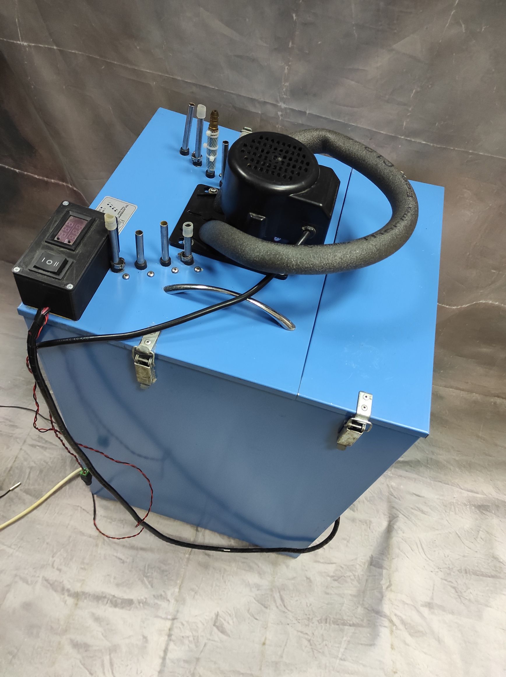
The chiller is a metal structure of a box-type with dismountable walls and a top cover.
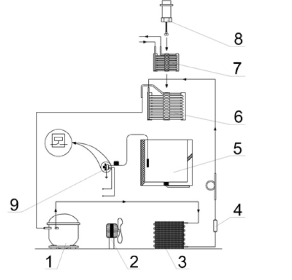
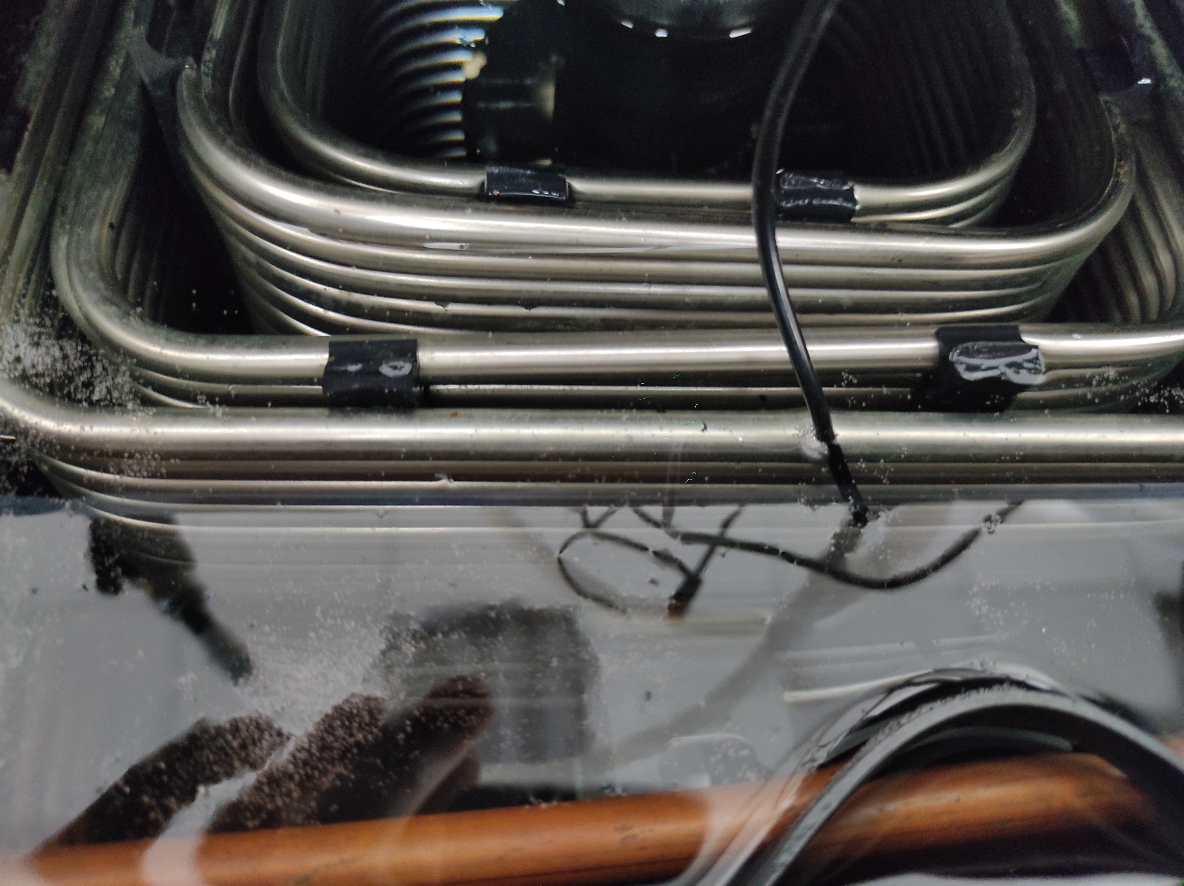
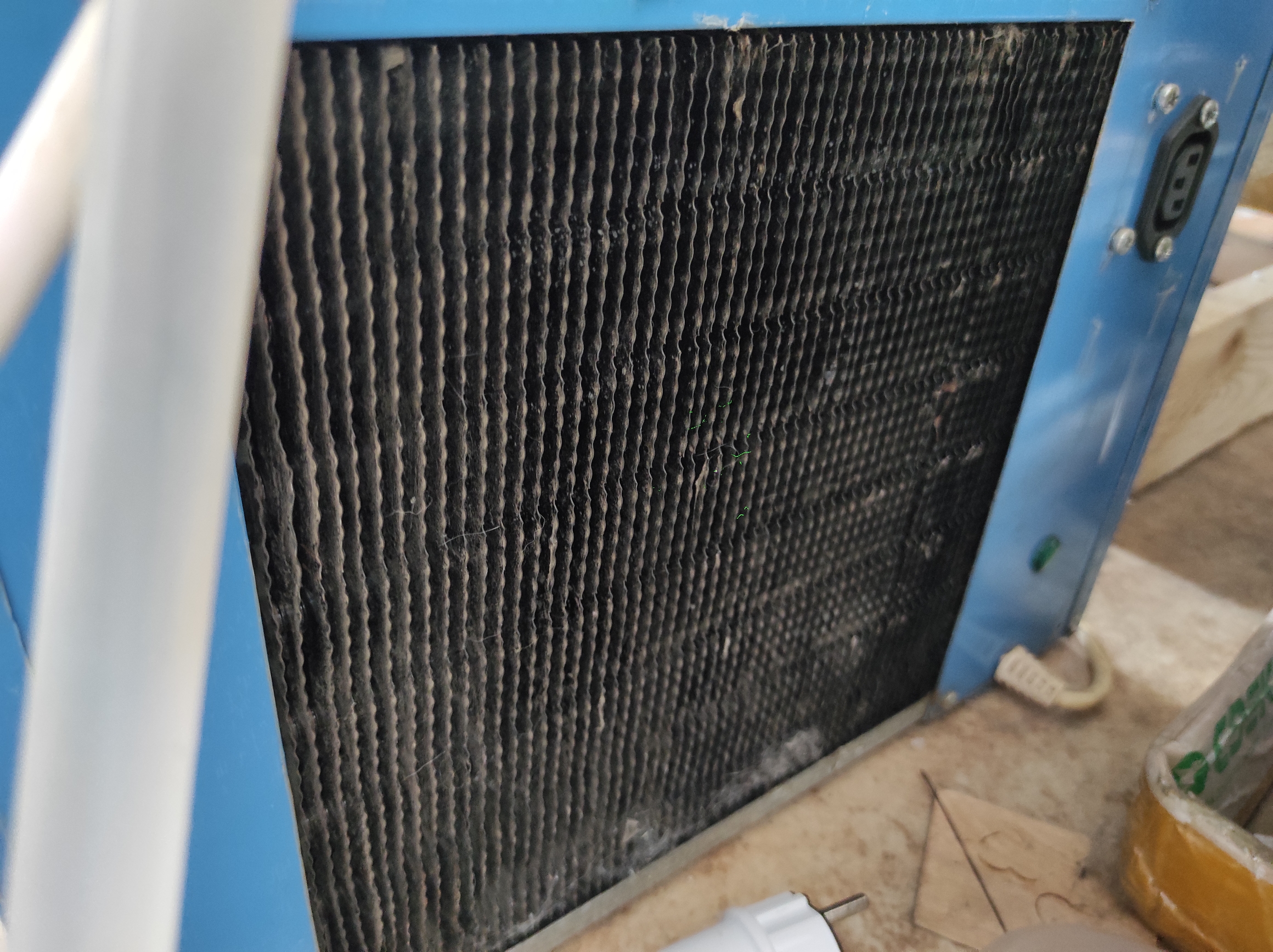
Inside, the chiller has a compression type refrigeration unit with a compressor (1), air condenser (3), dehydration filter (4), evaporator
(6), interconnected by means of soldered together copper pipes. All together they form a leak-tight system filled with ozone-safe R-134 coolant (see fig.1). The evaporator is housed inside a tub made of impact-resistant plastic and insulated on the outside by ` polyurethane foam.
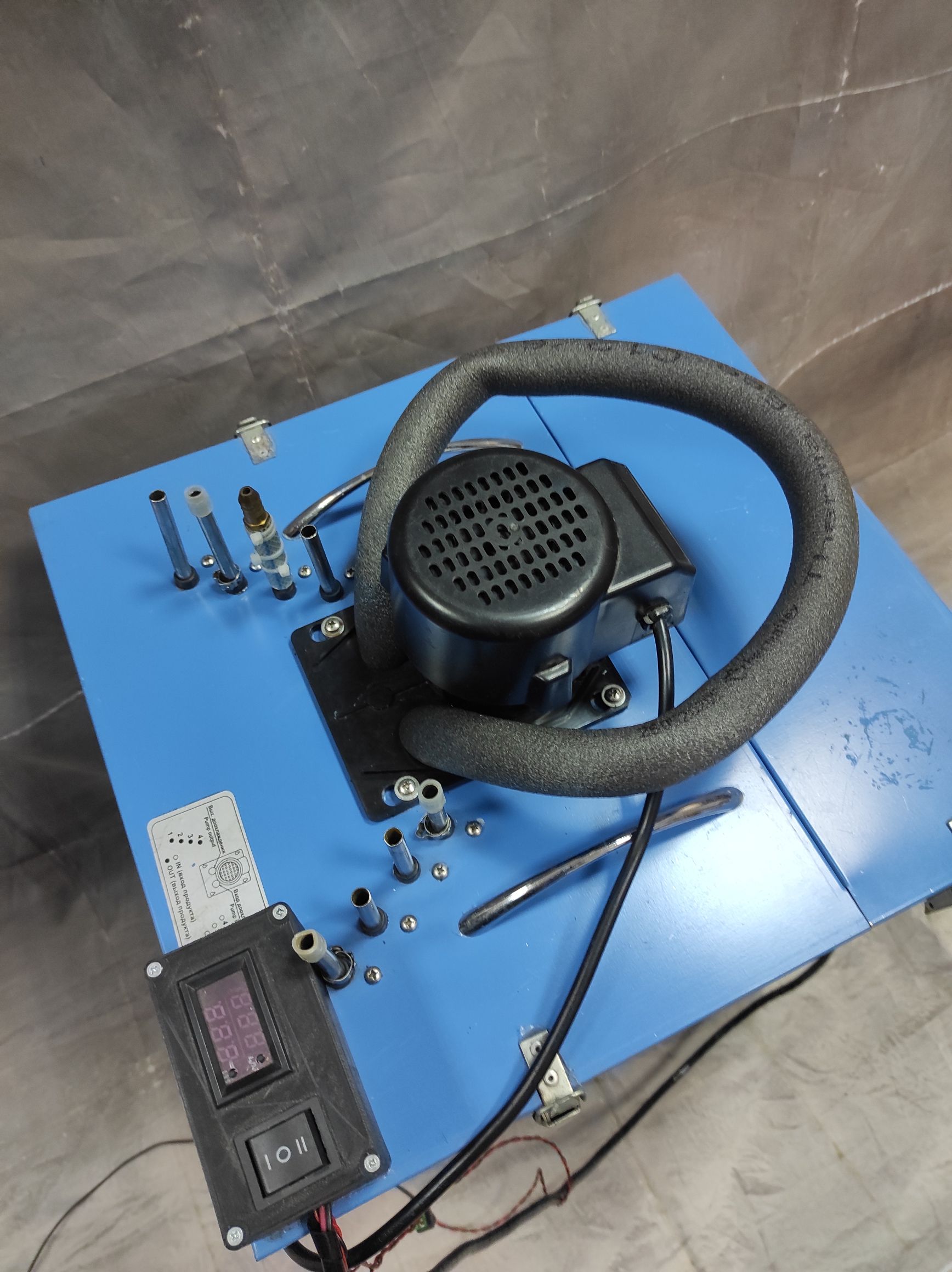
The thermostat (9) is designed to maintain the specified temperature of the water in the tub (due to the ice field bank regulation).
The fan (2) is used for forced cooling of the air condenser. The fan and the compressor work simultaneously, automatically turning on and off by the thermostat control. The ice in the tub forms in the way it does in a compression refrigerator.
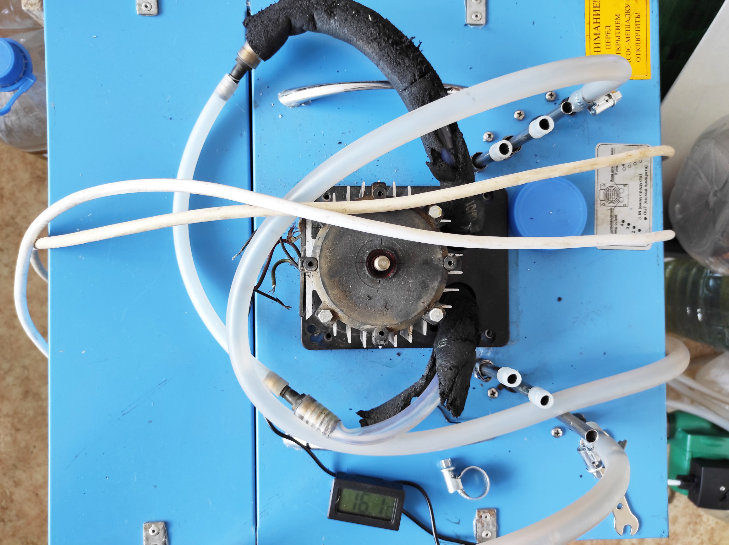
The agitator-pump (8) is used to increase the efficiency of the heat exchange processes between the formed ice bank and cooling water.
The chiller design provides access to the unit part of the refrigeration unit through decorative removable grills on the sidewalls of the housing.
How the chiller works
The operating principle of the chiller is based on the fact that the coolant vapors boiling in the evaporator of the refrigeration unit take away the heat, necessary for their boiling, from the tub water.
The water, while cooling, turns into ice on the evaporator pipes.
Pre starting procedure
Unpack the chiller and deploy at the workplace. The chiller should be deployed in a cool ventilated room with a 25 cm free space around it.
Connect the power supply to the chiller and check the insulation and grounding resistance for compliance with item 6.4.6. Use a grounded socket to connect the chiller.
Check the external condition of the chiller and power supply. Fill the tub with clean tap water to cover the upper pipe of the evaporator. Close the top cover and turn on the chiller for a short time to make sure that the refrigeration unit and the pump are activated. Listen to the sound of the working compressor, fan, and pump. It should be even without any side tones of mechanical origin.
After these procedures, the chiller is ready for operation.
Operation procedure
After connecting the chiller to the power supply (with grounding), gas, and product lines, filling the tub with water, and flushing the lines, turn on the chiller.
Depending on the temperature in the room and that of the cooling water at the input of the chiller, set the thermostat regulator to the position, at which the refrigeration unit will turn on.
When the temperature set by the position of the thermostat regulator is reached, the refrigeration unit will turn off, then set the regulator to the position corresponding to the max. formation of the ice bank. When the set volume of the ice bank is reached, the refrigeration unit will turn off.
It is not recommended to turn off the chiller after the work is finished as the power volume necessary for the ice formation is much higher than the power volume needed to keep the ice.
Maintenance
Maintenance of the chiller during its operation should be carried out exclusively by personnel trained in a special program, instructed in safety precautions, and who have the right to service trade and technological equipment.
No special equipment, tools, or devices are needed for the chiller maintenance.
The system of maintenance and repair of the chiller includes:
- regular servicing when using;
- routine maintenance;
- minor repair.
The regular servicing includes a routing set of operations to keep the chiller in good condition before, during, and after its usage.
The routine maintenance of the chiller calls for the performance of all the procedures within the scope of this document, regardless of the technical condition of the chiller.
Regularly before the start of the working day, make an external examination of the chiller for the detection of any mechanical damages of the unit as a whole and its parts as well, specifically, gas and product lines; pay special attention to the condition of the electric and ground wires of the chiller.
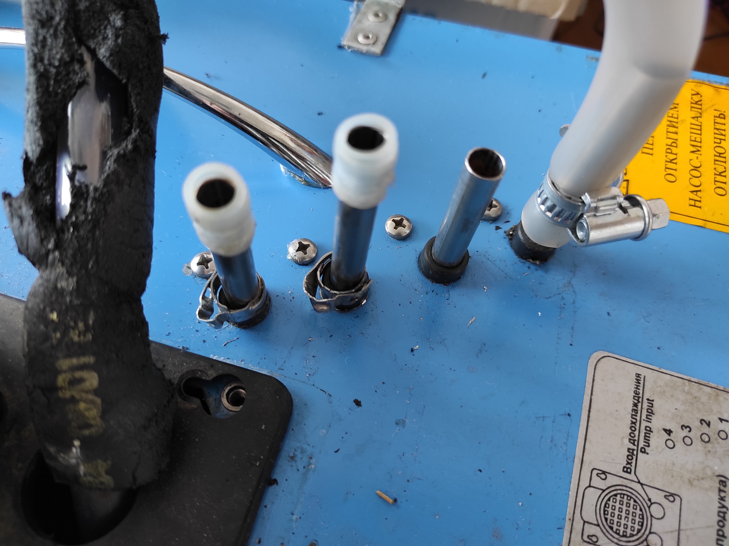
To avoid leaks, periodically check the tightness of the joints of the product pipelines.
Daily, check the water level in the chiller tub. Use a service hose to drain the water.
It is strictly forbidden to turn the chiller over because this might damage the compressor!
The top cover of the chiller must not be left open during operation. It is forbidden to put heavy items on it or block the ventilation grills.
When the thermostat knob is set at max. the ice thickness will be the greatest.
Turning on and off the refrigeration unit, the thermostat keeps the ice bank thickness stable.
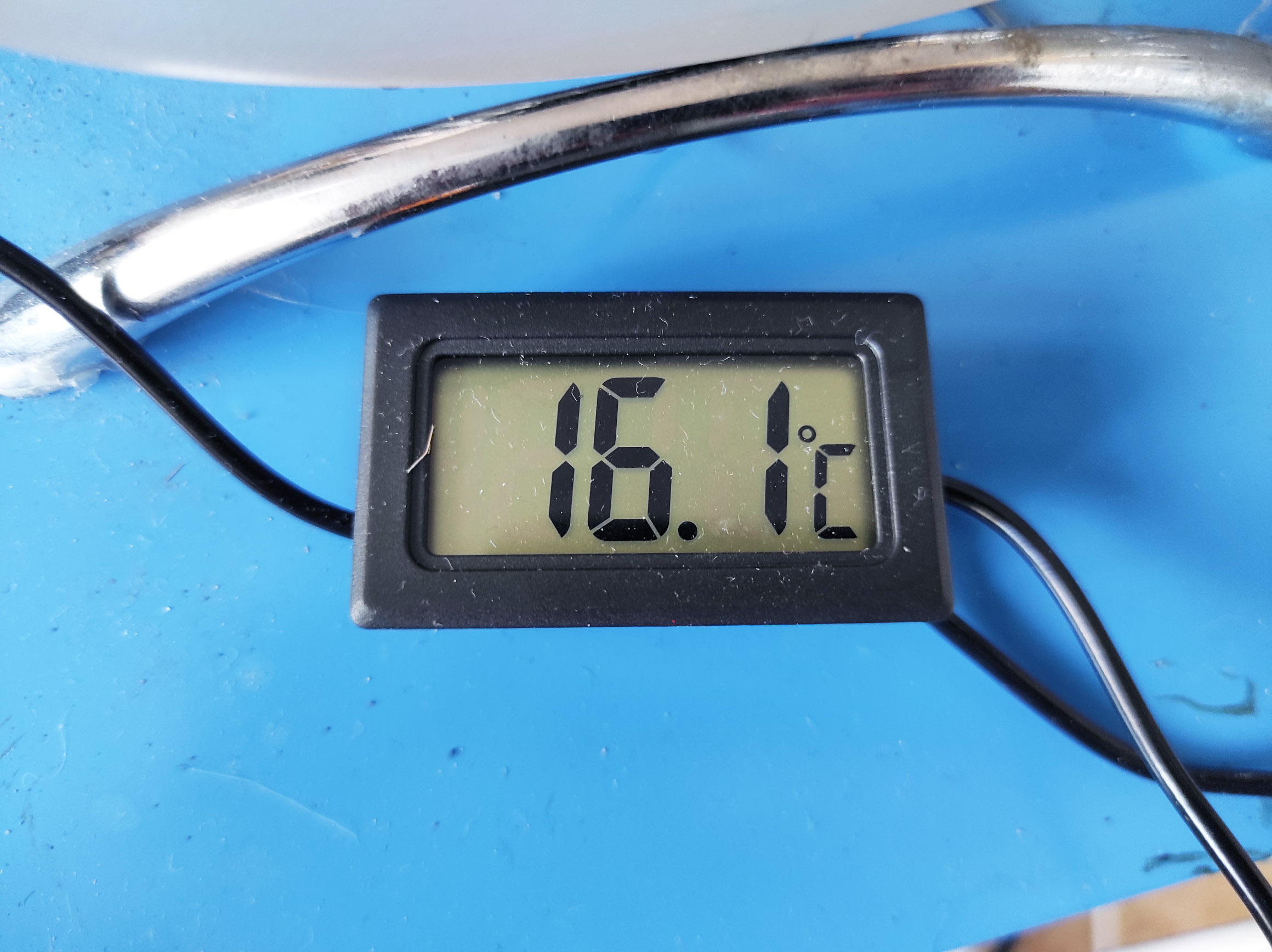
The temperature of the incoming water depends on the temperature of the laser itself. Until the ice field is completely depleted, the temperature of the water cooling the heat exchanger will be close to 0 ° C.
While the laser is working, is being cooled, and the ice field is depleting, the thermostat control turns on and off the refrigeration unit. When the ice bank reaches a volume sufficient to maintain the temperature set by the thermostat, the refrigeration unit will turn off.
The speed of the ice bank rebuilding depends on the laser operation intensity and the energy consumption for its cooling.

Extra components for the chiller
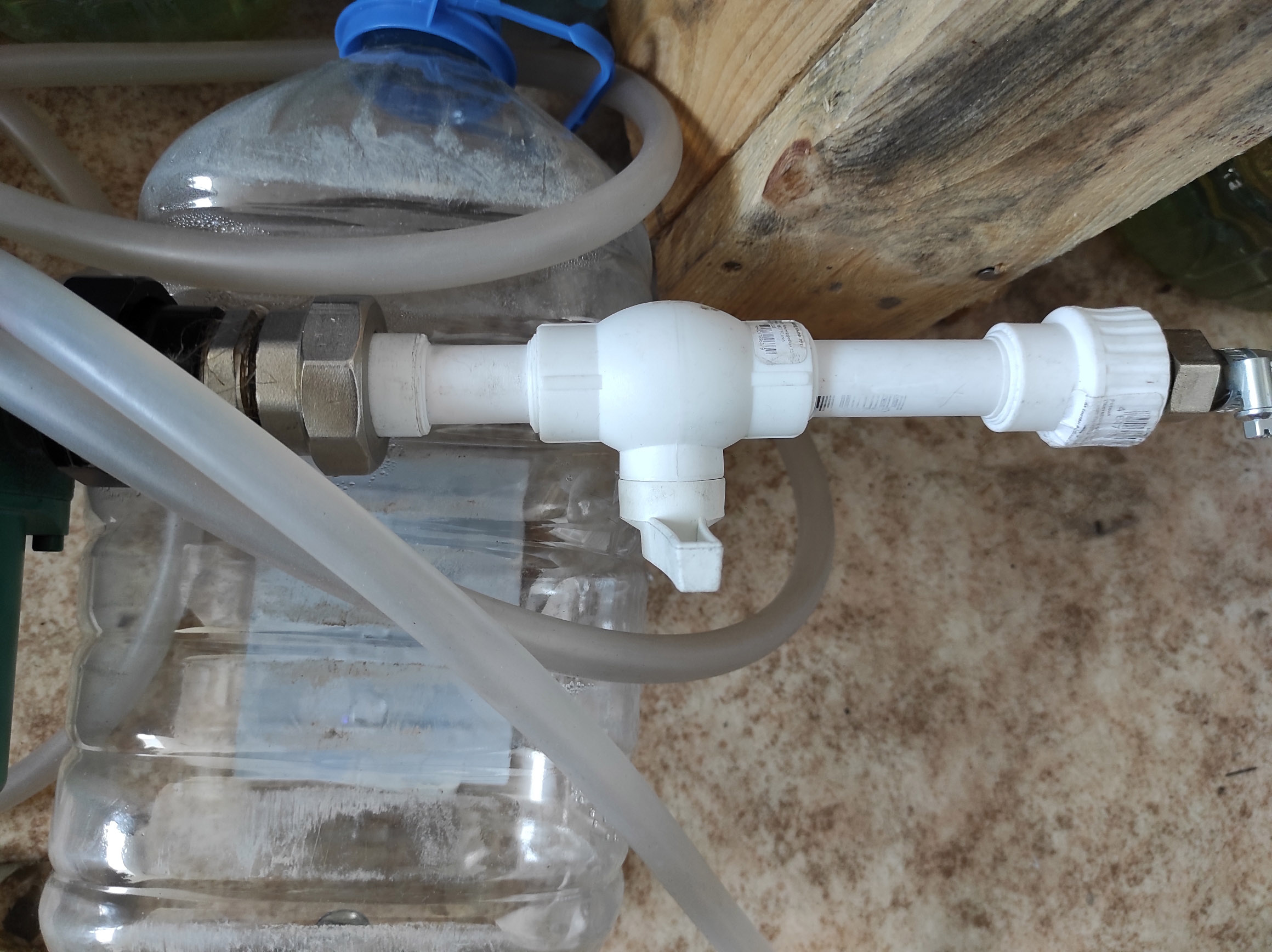
Combined detachable coupling (American), internal. Thread 20×3 / 4 ”
Degreaser universal Expert 0.5 l.
Pipe sealing flax PREMIUM 50 g MR-U (МР-У)
Adhesive sealant, anaerobic №3 20 g
Distilled water 5,0 l Glanz
Connection (tie-in) to the tank (container) with a gasket 3/4″ (brass), MR-U (МР-У)
Combined detachable coupling (American), external. Thread 20×1/2″
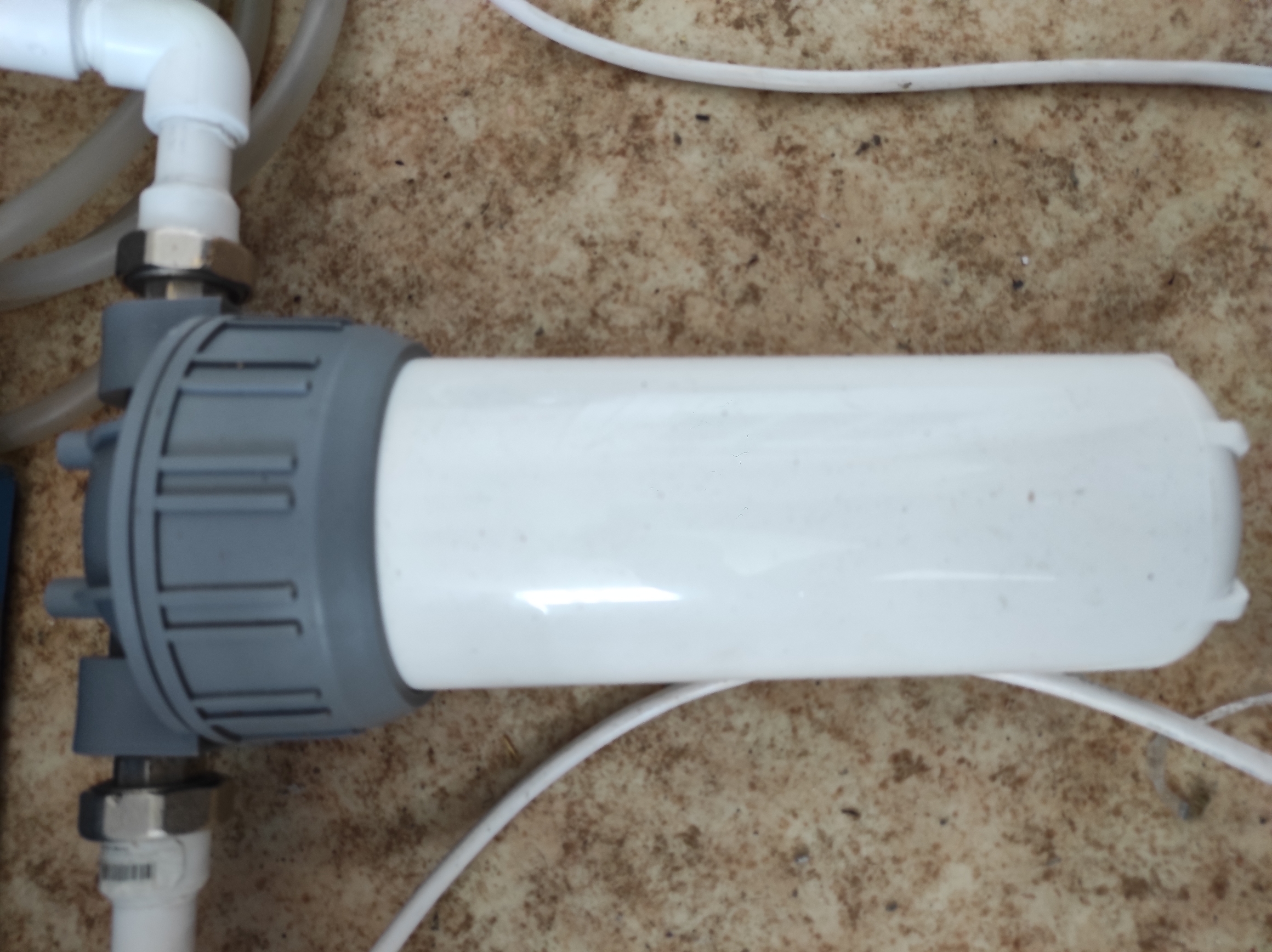
Cartridge Aquafor (5 μм) cold water
Main filter VM (BM)
Box-coupling PN25 D 20
Angle piece PN 25 90◦ int/int 20
Tank 10 l neck diameter 45 mm M434
Data specs:
| Chiller name | Cooler model |
| Typhoon-9 | |
| Consumed power, | 660 W |
| Cooler efficiency, no less | 18 – 117 l/h |
| 24 – 90 l/h | |
| 32 – 48 l/h | |
| Final chilled water temperature | 3-5 С◦3-5 С◦ |
| Ice field mass, not less | 14,0 kg |
| Time for the chiller to reach the mode at = 25 ° C | 6,5 h |
| Cooler weight without water and pack | 51 kg |
| Sizes | width 415 mm |
| depth 455 mm | |
| hight 695 mm | |
| The volume of water tub, no less | 30 l |
| Compressor cooling efficiency at t — 10◦С | 496 W kkal/h |
| 427 W kkal/h | |
| Coolant R-134A | 0,23 |
| Agitator-pump: | efficiency. 768 l/h |
| height of water 6,3 m | |
| Ventilator | Efficiency. 500 m^3/l |
| power 10/36 W |
https://www.temper3d.ru/publish/tochka-rosi/