Endurance presents a new engraving software (beta testing second release)
The new version of the program you can download by link
Endurance LaserService second release
Updated workflow:
1) Create [TASKNAME].sta file with g-code at beginning of work on task
2) Move head to start point of the picture
3) Create [TASKNAME].beg file
4) Start engraving
5) Stop engraving
6) Create [TASKNAME].end file
7) Move head to the initial position
8) Create [TASKNAME].fin file
If any error occurs – create [TASKNAME].err file with error code (files [TASKNAME].end and [TASKNAME].fin may not be created in this case).
[TASKNAME].log file created at the beginning of work and fill by messages about current processing.
updated software version >>> (08/06/2020) download LaserService (4)
And for paragraph 2 of your requirements, you will change in Laserserivce.ini before start
[IMAGE]
reverse_height=1
swap_width_height=1
Be sure to up update sketch in Arduino by new version
In log files X and Y may by be in different places
Endurance presents a new engraving software (beta testing first release)
Now you can engrave and cut just with Arduino board connected to your stepper motor drivers and that’s it.
Upload an image in the folder and the program will engrave or cutting.
A few things you need to follow.
- Download the Endurance LaserService 0203 edition
LaserService.exe – the program
LaserService.ini – program settings and Arduino settings
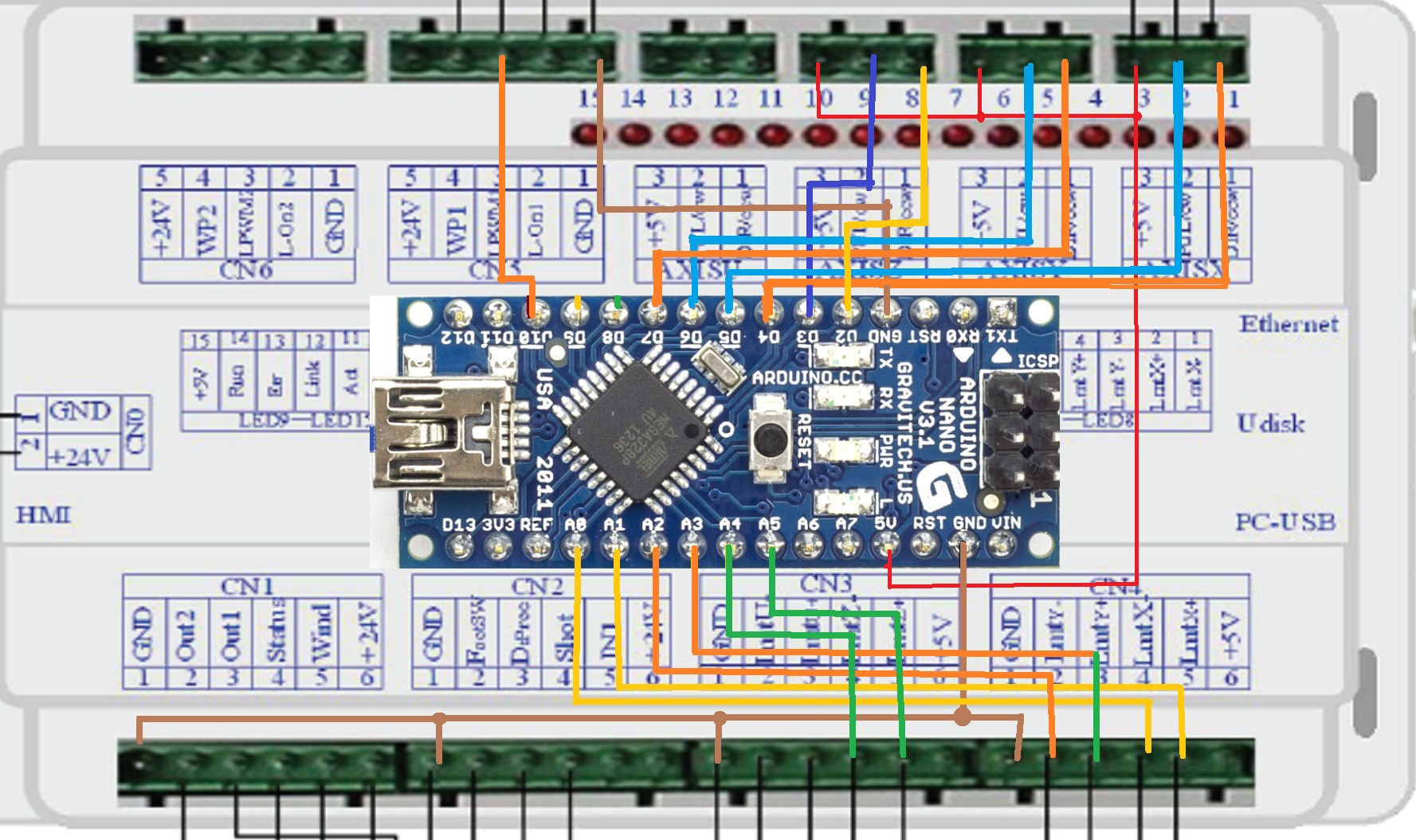
Schema.png – a pinout diagram for Arduino nano
Sketch_graver.ino – firmware for Arduino
Tasks.zip – a trial task for engraving
2. Pour firmware into Arduino nano using Arduino IDE
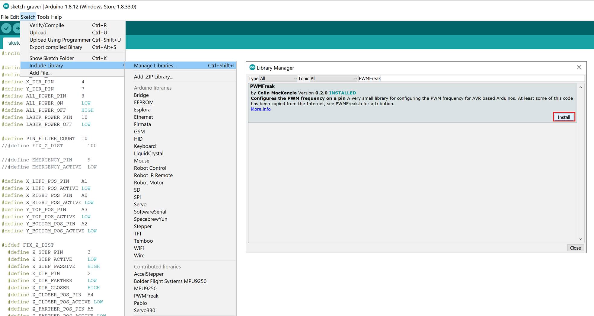
(additional PWMFreak library will need to be connected, see screenshot)
The service (Windows service) will be installed (to get started automatically when Windows starts) and launched immediately as a service.
LaserService.exe –install
To do this, you can create a link and execute it as in the screenshot
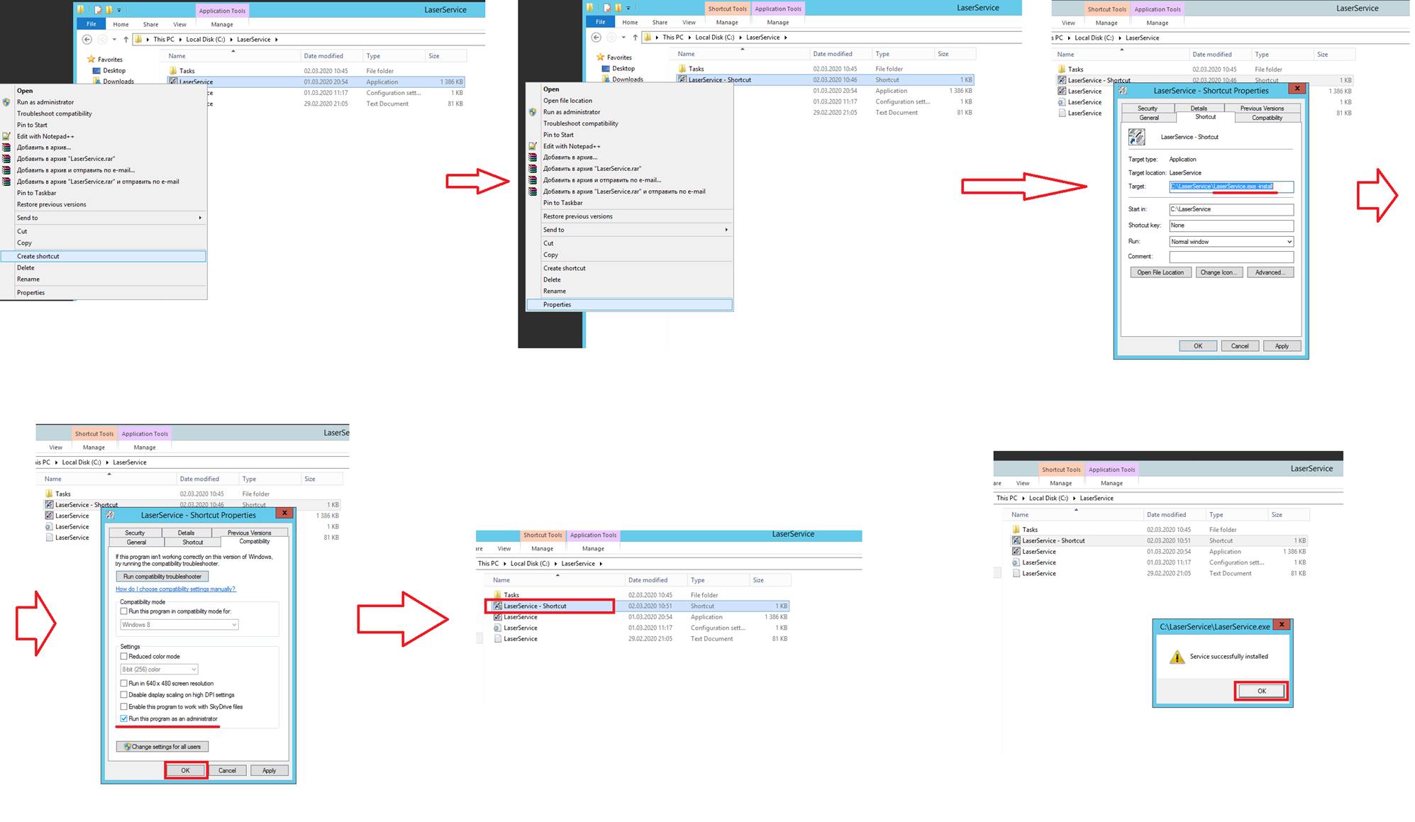
The service (Windows service) will be installed (to start automatically when Windows starts). And also immediately launched as a service
To configure the program you need to change LaserService.ini
[Arduino]
COMPORT = COM5 – com port on which Arduino is defined
[Hw]
invert_x = 0 – whether it is necessary to invert the output of the Arduino, which is responsible for the direction of the X axis
invert_y = 0 – whether it is necessary to invert the output of the Arduino, which is responsible for the direction of the Y axis
check_buttons = 0 – do I need to check the limit switches
steps_per_pixel_x = 8 – the number of micro-steps (or steps) per pixel on the X axis
steps_per_pixel_y = 8 – the number of micro-steps (or steps) per pixel along the Y axis
acceleration_coefficient = 10 – delay factor between the first step (slow) and the cruising move (at full speed)
power_max = 250 – maximum laser power during operation (from 0 to 255)
step_delay = 1000 – time in microseconds per half-pixel (with the specified number of micro steps) when moving at cruising speed (at full speed)
4. To start the engraving task, put the PNG and INI file in the Tasks directory.
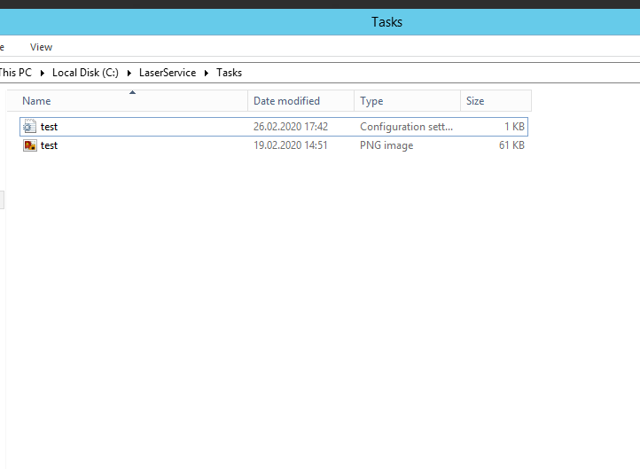
5. The program will start engraving or cutting.
For all questions regarding the operation of the program, a LaserService.log file appears, in which errors and current progress are indicated.
Arduino pinout general view
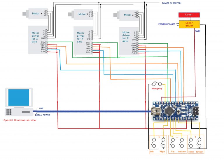
Pinouts for an Arduino
#define Z_STEP_PIN 3 //
#define X_STEP_PIN 5 //
#define Y_STEP_PIN 6 //
#define Z_DIR_PIN 2 // LOW = go from surface farther, HIGH – go to surface closer
#define X_DIR_PIN 4 // LOW – go right, HIGH go left
#define Y_DIR_PIN 7 // LOW – go down, HIGH – go up
#define ALL_ENABLE_PIN 8 // LOW – enable, HIGH – disable
#define EMERGENCY_PIN 9 // LOW – alarm, HIGH – off (pullup enable)
#define LASER_POWER_PIN 10 // LOW – laser power off, PWM – power on
#define X_LEFT_POS_PIN A0 // LOW – active, HIGH – off (pullup enable)
#define X_RIGHT_POS_PIN A1 // LOW – active, HIGH – off (pullup enable)
#define Y_TOP_POS_PIN A2 // LOW – active, HIGH – off (pullup enable)
#define Y_BOTTOM_POS_PIN A3 // LOW – active, HIGH – off (pullup enable)
#define Z_CLOSER_POS_PIN A4 // LOW – active, HIGH – off (pullup enable)
#define Z_FARTHER_POS_PIN A5 // LOW – active, HIGH – off (pullup enable)
Arduino pinout detailed (compatible for any CNC frame)
Compatible and tested board
Eleksmaker Mana board >>>
Software custom development extra tool
Our new windows service is continuously run, and check the directory for new task. New task will be represented as .PNG file and .TSK files in the specified directory.
TSK file should contain specifications of the task, such as scale, initial X/Y coordinates and so on (the exact format of this file will be later)
So then service start to work with controller (in this case this is the adruino via USB connection), and make engraving.
At the end of work service create .LOG file, G-code file and .FIN or .ERR file (all file names is the same as initial .PNG and .TSK files).
.FIN or .ERR files will be empty, only to display the status of the completion of work
if you have any questions let us know in LiveChat or email
