Introduction to CNC for a Total Novice
Part of a series by Graham Bland
Setting up a Laser
Contents
Setting up the SainSmart laser module on a 3018 Pro
Connecting the 2.5W Laser module
Connecting the 5.5W Laser module
Configuration changes to Add Jog buttons for the Z axis
Adding Custom buttons to LaserGRBL
$120, $121, $122 – [X,Y,Z] Acceleration, mm/sec2
What this covers (supposedly)
How to setup and use a laser module, specifically the SainSmart 2.5W and 5.5W on a 3018-PRO
This is one of a series I have written, I strongly recommend that if you are starting out you read Introduction to CNC for the Total Novice – Getting Started first!
Major changes are:
- This used to be part of my Introduction to CNC for the Total Novice – Getting Started but I split this out when I updated it as not everyone will have a laser and some may get one later.
- Less rambling
- Tidied up accompanying files
- General edits as I have learnt more
- Removed some specific values which really were only applicable to my use.
- Added exploration of acceleration values
Introduction
I am producing this as a document, mainly because It is an edited series of notes I made, partly because I am tired of watching instructional videos on YouTube which play at Mach 2 and so I am constantly stopping, rewinding and re-watching. Also I have been told I have a body made for Radio, a voice most suited to the Deaf and I still haven’t worked out how to use the video camera on my phone properly.
Disclaimer
Yeah nowadays it has to be included, and it makes sense as I accept NO liability for anything I may say, write or think.
- I am a total novice (or was when I started out). I MAKE NO CLAIM THAT ANYTHING I SAY IS CORRECT! All this is based on searching the Internet, forum comments…. and my own experiences.
- This is based solely on the one I have, if there are variations or different versions out there I have not seen them.
- If you have and are using a Laser module, even the lowest powered is powerful enough to destroy your vision completely, and that of any pets, children, spectators etc. SO EXCLUDE THEM AND USE THE GOGGLES!
- These are power tools, sharp pieces of metal designed to cut things while rotating at high speed and throwing small bits away also at high speed. Keep everybody’s fingers out! A wood chip flying up your nose is nothing to be sneezed at, never mind in one of your eyes.
- Take account of the materials you are using and take adequate precautions, dust and ashes can be harmful.
- I work in mm. Why anyone still uses inches for design work is a mystery. But then I still think of temperatures in Fahrenheit, anything beyond 100m in miles and property plot sizes in acres!
- I have been told by lots of people that my sense of humour is at the least a bit strange. I do not apologise for it.
Any corrections, clarifications or discussion welcome. You can find me on the Facebook SainSmart
Genmitsu CNC Routers Group as Graham Bland. https://www.facebook.com/groups/SainSmart.GenmitsuCNC/
Accompanying files
NOTE: Facebook has a problem, it will not allow compressed (.zip, .gz, ……) to be uploaded to the Files section of any group, but it bases this decision solely on the file extension, not the contents.
It is easy to bypass this by changing the file extension before uploading, I use .zip files, and rename them to .zipp This means that after downloading you will have to reverse this by renaming any xx.zipp file to xx.zip, windows will issue warnings that you are probably going to make the file unusable, just ignore it and rename anyway. Then you can open and extract the files as you wish.
So there should be 2 versions in the files section. One an xx.pdf which is the basic words, and if there are any accompanying files with it an xx.zipp with the .pdf and everything else.
Accompanying files for this are:
| GBCustomButtons.gz | My custom button setup for LaserGRBL, including all the coding, icons and setup. Just import into LaserGRBL. |
| TracingTest GCode-V2.xlsx | Excel spreadsheet which generates simple GCode for some setup tests, mainly for a Laser. It allows you to easily change the speed, feed with other parameters. Draws vertical lines, an array of boxes with varying speeds and feeds, a focusing test and a more complex shape to determine the effect of acceleration rates. If you don’t have Microsoft Excel sample GCode files are provided which of course can be edited using a text editor. |
| LaserDrawLines.nc | Laser Draws/cuts/engraves 10 vertical lines, settings are in comments at the start of the .nc file. |
| LaserDrawBoxes.nc | Laser Draws/cuts/engraves 5 rows of 10 boxes, settings are in comments at the start of the .nc file. |
| LaserFocusTest.nc | Laser Draws 11 vertical lines above a set of reference marks. The Z axis is varied between each line with the centre line being at Z0. A set of reference marks at a higher power are drawn first to show where each line should be. If the laser focus is exact the centre line should be perfect, the ones to the sides, less perfect. Settings are in comments at the start of the .nc file. |
| LaserAccelerationTest-30.nc | Draws a more complex shape designed to determine the effect of increasing the $120-122 acceleration values when using a laser. Acceleration values set to 30mm/sec/sec |
| LaserAccelerationTest-1000.nc | As above but with acceleration set to 1000mm/sec/sec |
| LaserAccelerationTest-5000.nc | As above but with acceleration set to 5000mm/sec/sec |
| SpindleAccelerationTest-30.nc | Draws a more complex shape designed to determine the effect of increasing the $120-122 acceleration values when using a Spindle Motor. Acceleration values set to 30mm/sec/sec |
| SpindleAccelerationTest-1000.nc | As above but with acceleration set to 1000mm/sec/sec |
| SpindleAccelerationTest-5000.nc | As above but with acceleration set to 5000mm/sec/sec |
Notes:
TracingTest GCode-V2.xlsx
This is a Microsoft Excel spreadsheet with a number of sheets, each for a different function. All it does is concatenate predefined GCode with the parameters you enter. There is no checking performed on the parameters so select the values with a little care. Documentation is provided within each sheet as to what it is supposed to do.
Each sheet is protected to prevent inadvertent modifications, there is no password required to unprotect so if you want to make additions or modifications feel free. For the same reason some columns are hidden, these just contain some simple intermediate calculations where the speed and feed are varied. If you do modify this and republish it please give me some attribution as the original author, I am as vain as the next person!
.nc files
For each sheet in the spreadsheet I have included one or more sample .nc files, with rough speed and feed settings for a 5.5W laser using white printer paper as the stock. Where a bit is used I suggest a V bit engraving on wood (I used MDF).
Some of the files may have some $nn=y commands to change some router settings, setting Laser Mode on or off is the most common. But beware anything changed by the $nn=y command is permanently saved by the router until you change it.
Each file has comments at the top showing the settings in use, open using any text editor.
THE LASER MODULE
I started out with 2.5W and later upgraded to a 5.5W laser module. Both are SainSmart blue Diode lasers with a wavelength of around 450nm.
What does a Laser do?
Basically it concentrates power into a tiny spot creating an intense heat at the focus point. This will heat up whatever it is focussed on and depending on the material cause it to burn, melt or vaporise, often a combination of the three.
SAFETY!
Some of the things missing off the ‘can engrave’ list are the retina of the eye and flesh! OK all this is in the disclaimer but is worth repeating!
It doesn’t even need to be focussed directly in your eye to burn the retina, Eyes did not evolve to deal with Lasers! Everyone should know that looking directly at the sun is a very bad idea.
This is the reason that the laser comes with a pair of safety goggles, USE THEM! They are designed to limit the frequency of the light which can pass to prevent any damage, they tend to be specific to particular lasers which use different wavelengths of light, the supplied goggles are designed for use with these lasers which use around 450nm as the wavelength. If you use a different laser then you will need something suitable for the frequency of that laser.
Another consideration is being careful using cameras when the laser is on, it can burn out a CCD in a digital camera very easily. A more modern CMOS is more resilient but even so…
A second other consideration is the burn, melt or vaporise bit! If cutting a flammable material, for example paper, it is quite possible to set it on fire. If cutting a material such as MDF from which the dust can be toxic, and when burnt the fumes are also toxic. Hitting a resin pocket in a piece of pine can cause a fire.
So at the absolute minimum use a in a well ventilated area, wear a mask as well as the goggles if there is a possibility of the stock being toxic and keep a very damp cloth handy. But it’s your health and you have been warned.
Setting up the SainSmart laser module on a 3018 Pro.
My goals in this were to learn how to set up, mount, and focus the Laser module.
- Mounting and connecting the Laser.
- Setting it up, focal length and focussing.
- How to mount the stock, initially for cutting paper.
- Determine what feed rates and laser power works best.
- Determine how the choice of material affects the choice of laser power and feed rate settings.
Equipment I am using:
- SainSmart Genmitsu 3018-PRO
- SainSmart 445nm 2.5W laser module
- SainSmart 445nm 5.5W laser module
- Woodpecker CamXTool 3.4 and Camtool 3.3 router motherboards
- Software – LaserGRBL v3.019
Mounting the laser
Connecting the 2.5W Laser module
Cooling fan at the top, square which conveniently fits in the groves in the spindle mount, 3 pin connection on the top which on mine says SW=0 ON SW=1 OFF. The Camtool 3.3 motherboard also has writing which says LaserA S=0 On. LaserB S=1 On. Just match them up, my 2.5W one should be plugged into LaserA, the white one, the 5.5W goes into LaserB. On the latest motherboard board (3.4) there is only one Laser port. My 2.5W laser is not compatible with the 3.4 board probably because the only laser port requires a Laser which is on when the signal is 1 or high. Other motherboards will be different.
Connecting the 5.5W Laser module
Cooling fan at the top, square which conveniently fits in the groves in the spindle mount, 2 x 2 pin connections on the top which go to the separate supply unit. This has another cooling fan, an on off switch for the Laser and a 3 pin connector which goes to the Router motherboard, on a Camtool 3.3 motherboard this is LaserB, the red one, on the newer board there is only one. Other motherboards will be different!
Unplug the spindle motor from the motherboard and remove it from the holder. NOTE: You only need to do this if it is already plugged in and mounted! If not skip this step.
Slide in the laser module with the corners going into the slots in the holder. You may need to carefully pry the mount open a bit. I use the end of one of the spindle spanners if needed.
There are some physical differences between the two laser modules, the 5.5W has a ‘heat sink’ (the black square bit) height of 65mm, the 2.5W is 59mm. When using the 2.5W I align the top of the laser heat sink with the top of the bracket, just as it is easy to put it in the same position when I change it out and I didn’t want to cover up the cooling fan. Also it seems about the right height to cut thin material allowing maximum Z travel to adjust for thicker stock for engraving.
For the 5.5W I just align the top 6.00762mm (very approximately, it’s not that critical) above the top of the bracket. This leaves the business end of the laser in about the same position for both. I have made a small mark on the front left corner of the 5.5W heat sink in line with the top of the mount for easier future alignment.
The only reasons that this is important is that it maximises the Z axis movement on my machine to allow me to use different thicknesses of stock without having to think about it every time I mount the laser.
And a mild case of OCO. (This used to be referred to as Obsessive Compulsive Disorder or OCD. But really – DISORDER, come on!! So I now refer to it as Obsessive Compulsive Order or OCO!)
For the 5.5W you will also need to put the separate supply unit somewhere, I mount mine using a strip of self adhesive Velcro on the back of the top frame roughly in the centre.
Tighten the clamping bolt on the motor mount and everything is ready to go, well nearly!
Startup Warning
I have found that both powering on the router and connecting it to software on my PC can cause the laser to fire for a short while, this also happens when powering on the router.
This can damage the stock and the first time I did not have my safety goggles on. It certainly burns a dot through paper wherever the laser happens to be. So far I have no idea why this is happening, but it makes sense to put something non burnable under the laser before turning the router on and connecting to LaserGRBL.
Focussing the Laser
The laser unit has a knurled adjustment knob at the bottom, this screws onto a threaded shaft which contains the focussing lenses. The shaft is prevented from (easily) slipping by a spring mounted inside the laser which keeps some pressure on the shaft threads.
Moving the threaded shaft in and out of the laser body adjusts the focussing as it contains the lenses; turning the adjustment knob should move the shaft in and out.
As delivered the adjustment knob on one of mine was loose. So all turning it did was unscrew it and screw it in onto the shaft WITHOUT affecting the focus. The focussing knob just has a hole in it so does not affect the focus; it is the movement of the shaft in and out of the laser body that does this.
A small drop of thread lock on the inside of the adjustment knob and screwing it tightly onto the end of the shaft solved this problem.
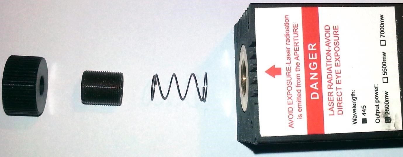
I would like to point out that the adjustment knob has been placed the wrong way round in the above image purely for random illustrative purposes!!!!
If this is a problem and you take the threaded tube out of the laser body just remember which end went into the laser. I have no idea if this would make a difference, probably not, it’s just easier not to find out!
It wobbles! And it is too easy to turn. First time through after focussing it I applied a dot of hot glue to the junction of the shaft and the laser. After reading the idea on the Facebook group I then took it out, wrapped a bit (a bit, 1 ½ turns are enough, not trying to make it waterproof!) of plumbers PTFE tape around the shaft, being careful that the tape will not overlap the end. before screwing it back in. Now the wobble is much less pronounced and although it still turns it is more difficult, making it more likely to stay in the same place but still allowing adjustments to be made.
Focussing is basically getting the beam down to a tight point. If it is a lot out of focus, well, you might as well use a cheap torch!
Setting up LaserGRBL
A bit of an aside but isn’t really. I use LaserGRBL especially for focussing the laser as it can be easily customised with some, I find, useful extensions, and it’s free! If you use something else then you will need a way to turn the laser on and off preferably at its lowest power setting.
LaserGRBL can load GCode, image files, both pictures and vector graphics and generate GCode optimised for laser engraving and cutting from them. Download and use for free at https://LaserGRBL.com/en/download/
As supplied its fine but I have added some custom buttons to help in focusing the laser and positioning the image. It is easily customised in this way.
The extras I want are:
- Turn the laser on and off, but at a very low power so it doesn’t burn (much), this makes it possible to see where it is on the stock and to focus it without being so concerned about getting a finger in the way, it’s still not a good idea to engrave on your fingers no matter what the power setting.
- Turn the Laser on at low power for 2 seconds. Then off to check the focus and size of dot made.
- Set the router to operate in Laser Mode (more later).
- Go to the bottom left, middle or top right of the engraving, easy to get the positioning right and to check for sizing errors before starting to engrave.
A quick overview of the LaserGRBL main window, well there are tutorials and details available on the http://LaserGRBL.com/en/ website. Look at http://LaserGRBL.com/en/usage/user-interface/ for details.
Configuration changes to Add Jog buttons for the Z axis.
Out of the box LaserGRBL does not have any jog buttons for the Z axis shown. (Jog is moving the position of the tool around the stock manually, without any cutting, normally used to set the position of where you want to start). OK it doesn’t use the Z axis when converting pictures etc to GCode. But these are useful for setting the height of the laser above the top of the stock. This is easily corrected, in the top bar click on Grbl then select Settings. In the settings window select the Jog Control tab and tick Show Z up/down control. Then save.
Now you should see at the right of the Jog controls a set of Z axis control buttons allowing coarse and fine movement of the Z axis. The set Zero Point button (the globe) sets zero for all axes. Use of these buttons is the only time LaserGRBL will move the Z axis. (Unless you are loading GCode files which move it.)
Adding Custom buttons to LaserGRBL
LaserGRBL allows you to add custom buttons to the bottom button bar, after the lightning bolt, padlock and globe. What these do is send GCode or setup commands to the router.
Read http://LaserGRBL.com/en/usage/custom-buttons/ for background.
To do this in one hit I there is an associated file in the .zip of GBCustomButtons.gz To import the buttons directly into LaserGRBL right click in the custom button area, select Import custom Buttons and select the GBCustomButtons.gz file. You will have to confirm each button so just click Yes, Yes, Yes…. You can delete individual buttons if you don’t want them by right clicking on one and selecting Remove Button.
But to understand what they do: (Skip this if you want, I will be devastated but will recover eventually)

Turn Laser on at low power for positioning and focusing. This is a toggle button, click once to turn on, click again to turn off.
| GCode On | Description |
| S1 | Set Spindle Speed/Laser Power to Lowest setting |
| F100 | Set a Feed rate of 100mm per minute. (Included as the Grbl board was generating errors saying no feed rate was defined) |
| G91 | Set positioning as relative, otherwise depending on any previous commands it could return to a home position |
| M3 | Turn on the Laser/Spindle permanently |
| G1 Z0.1 | Move the Z axis up 0.1mm (This is needed as M3 doesn’t actually turn on the laser until a movement occurs) |
| G1 Z-0.1 | Move the Z axis down 0.1mm or back to where it started. |
| GCode Off | Description |
| M5 | Turn the Spindle/laser off. |


Framing buttons
Simple buttons to go to the bottom left of the ‘image’ the middle and the top right. Each is a one press button which moves without affecting the laser on/off.
LaserGRBL allows the GCode to contain expressions which are evaluated before sending the actual code to the router. See the LaserGRBL website for details.
So all three are just Buttons, click once to execute, with respective GCode of
- G0 X[left] Y[bottom]
- G0 X[left+width/2] Y[bottom+height/2]
- G0 X[right] Y[height]
Turn on at low power for a preset time

This turns on the laser at its lowest power for 2 seconds then turns it off. Useful for checking position and also for checking focus to see how big a dot it makes. NOTE Depending on the material even at the lowest power this can still burn the stock!
Again just a Button, click once to execute.
| GCode | Description |
| S1 | Set Spindle Speed/Laser Power to Lowest setting |
| F100 | Set a Feed rate of 100mm per minute. (Included as the Grbl board was generating errors saying no feed rate was defined) |
| G91 | Set positioning as relative, otherwise depending on any previous commands it could return to a home position |
| M3 | Turn on the Laser/Spindle permanently |
| G1 Z0.1 | Move the Z axis up 0.1mm (This is needed as M3 doesn’t actually turn on the laser until a movement occurs) |
| G1 Z-0.1 | Move the Z axis down 0.1mm or back to where it started. |
| P2 | Pause for 2 seconds (NOTE: Grbl implements the P as being in seconds, some others use milliseconds) |
| M5 | Turn off the Laser |

Set Laser Mode
This sets the laser mode ($32)setting to ON, just a button, click once to execute. NOTE: the laser Mode is saved permanently by the router until you change it, so if it has already been set there is no need to do it again, but remember to turn it off when/if you put the spindle motor back in. GCode is $32=1
Hey a Laser is a single focused beam of light? Well, Yes but certainly for a Diode Laser also Not quite.
It’s worthwhile I think to do this carefully, follow these steps and you will only have to do it once.
Focus point
To cut or engrave efficiently we want the laser beam to be tightly focussed into the smallest possible point at the top of the stock. This depends on the distance from the laser emitter to the spot and is controlled by the position of the focusing lens as adjusted by the focusing knob.
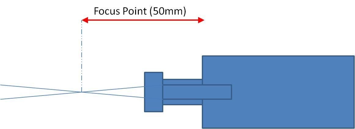
Simply put the focal length is the distance from the lens to the point where the beam of light becomes a very fine dot and then expands again.
From what I can find the focal length of these lasers should be within the range of 25-75mm, but I have not found what I consider to be a reliable source for this. I cannot easily measure the distance from the outside of the lens, but I can measure from somewhere else to the focus, I will call this distance my focus point.
So practicality plays a large part. I have set my focus point at 50mm from the bottom of the laser heatsink, the black square bit, to the top of the stock.
Why this distance? Well just because it seems to make sense with the way I have it set up with the laser, at the lowest point of the Z travel the focus is going to be just below the top of the Spoilboard, and it leaves the maximum room for me to move it up to allow for thicker stock.
Anytime I start a new piece of work if I adjust the Z axis so that there is 50mm between the bottom of the laser heatsink and the stock it should still be in focus as long of course as the position of the focussing knob has not changed. Minor adjustments may be needed!
How to focus
Any time the laser could be on make sure you and any spectators are wearing laser goggles and exclude all pets, or get them some laser goggles as well!!!
It helps, and makes it easier to repeat if you have a guide to position the laser. I have cut a piece of a plastic drinking straw 50mm long which I use as a guide piece. Why a drinking straw? Well it was what I had, is firm enough to give an accurate distance and soft enough that if I jog down a bit too far there are no nasty grinding noises. I think I will shortly change it for a small piece of wood or solid plastic as that will be more resilient, maybe even something carved in a T sort of shape.
Using the Z axis jog controls and a ruler (or your guide piece) position the bottom of the laser heat sink 50mm above the top of the stock.
The choice of stock is important while focussing, even though the laser is at the lowest power, you don’t want anything that will start to burn or cut as that makes it very difficult to maintain the distance and see what you are doing. After a bit of experimentation I ended up using a piece of steel, in fact an old 0.1mm feeler gauge, it doesn’t burn and makes it easier to see what is happening to
the beam. Also I know that after focussing I just need to move the Z axis down by 0.1mm to be exact. Brass, aluminium I am sure would work well but I am just using what I had.
NOTE! Apart from having laser goggles on keep your fingers OUT of the path of the laser. To turn the focussing knob be very careful, or get someone else to turn it! (If asked I will deny saying that!)
Use the custom button in LaserGRBL to turn on the Laser at low power (or any other method). Rotate the focussing knob until the centre of the laser ‘colour’ is a tightly defined dot. Simple?
Well not quite as simple, No pictures provided, Lasers can damage camera sensors, especially older CCD ones.
What you will see is a blob within a much wider shape, depending on the laser. The aim is to make the brightest part of the blob in the middle as small and as bright as possible. Once you get it close the final result can be a bit subjective, especially if like me you wear glasses under your laser goggles to be able to see anything in focus. Putting a bright white light from a torch on it can also help by making everything but the centre dot less visible.
If you are using a burnable material as your stock and the laser starts to burn through, it almost certainly will, turn it off, move the beam a few mm or so left or right and repeat. This is so you are still measuring the focussing point measured at the top of the stock.
Checking the focus.
In the accompanying files there is LaserFocusTest.nc this is a simple GCode file which first cuts 11 markers just to show where the lines should be, then cuts 11 lines. BUT when cutting the lines the Z axis is first moved down 5mm and moved up by 1mm between each line starting on the left. So at the left the focus is 5mm out, too close and at the right is 5mm out, too far away.
(If you want to change the settings in the .nc file and have Excel use TracingTest GCode GeneratorV2.xlsx, or a text editor will do but it’s more difficult).
If everything is perfect then the resulting lines should be symmetrical about the middle and the one in the centre should be the best. If not adjust the focus a little bit, move the paper to a new position or jog the laser and try again.
NOTE: IF YOU ARE GOING TO RUN THIS AND HAVE SET UP YOUR LASER ACCORDING TO MY
SUGGESTIONS THERE IS NOT 5MM OF DOWNWARDS TRAVEL ON THE Z AXIS!!! SLACKEN OFF THE
CLAMPING BOLT ON THE MOUNT, SLIDE THE LASER DOWN 5MM, RETIGHTEN THE BOLT AND THEN RESET THE DISTANCE BETWEEN THE STOCK TOP AND THE BOTTOM OF THE LASER HEATSINK! ONCE FINISHED SLIDE IT BACK UP AGAIN.
You should get something like this (or not, it took me quite a few tries):
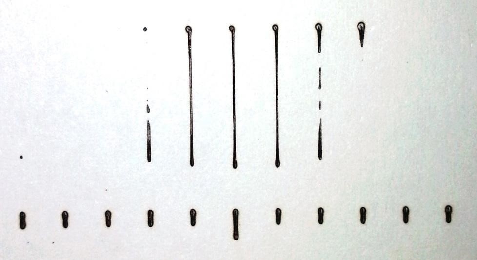
It does illustrate the importance of correct focus and Z axis positioning! The outer lines which are +/- 5mm and 4mm don’t even scorch the paper, 3 and 2mm aren’t great, -1 to +1 seem OK. This obviously depends on the stock, feed and speed you are using. If your ‘good’ lines are off to the left then your focussing point is too far out so screw the focussing knob in a bit, if they are to the right screw it out a bit then retry. NOTE: ’a bit’ is a very technical term which I use often, in this case it means exactly the correct amount, but remember as standard the Z axis moves 1mm between each line! Why do you think I am using very cheap printer paper to perform these tests? Also I don’t know the pitch of the threaded shaft on the laser or how many turns it takes to move the focus point by 1mm.
SERIOUS NOTE: If you turn the laser up to max power and a low feed rate you will probably see all of the lines which defeats the purpose so adjust the feed and speed accordingly until at least the outer lines do not show up.
First time through I then applied a dot of hot glue to secure the shaft to the laser to prevent it changing. Hot glue will secure it, but can be peeled off later if needed. Second time through I had used a bit of plumbers PTFE tape on the shaft before screwing it back in, if using PTFE tape make sure the inner threads are not covered, don’t want anything in the way of the beam!
A better way may be to add a locknut to the laser shaft, but I don’t have one that fits!
I have no idea if the focus will change over time, I don’t think it will, but have no reasoning to back that up. So I will check it every so often just to make sure it is still a tight spot.
Troubleshooting
| Symptom | Think about |
| Focus doesn’t seem to change. | Check the end cap at the end of the threaded shaft is secure. The focus is changed by moving the threaded shaft in and out of the laser body, moving the cap by itself has no effect. |
| Focus is set but it stops cutting on parts of the stock. | If you haven’t already then attach and level a Spoilboard and make sure that the top of your stock is level. You can test this by re measuring the distance from the stock top to the laser at different points. |
| I cannot see the dot easily when focussing. | Use something semi reflectable like a piece of steel to focus on. Shine a bright white light on it (torch) to help hide the bits round the edges. Wear Glasses? |
| …. | I’m making it up here but take the threaded shaft out of the Laser. Make sure the cavity is clear, the spring moves freely and the lens assembly is clean. |
Laser Mode
Grbl has a setting for Laser Mode, $32, $32=1 sets Laser Mode, $32=0 sets it off. This changes the behaviour of the router slightly; the laser or spindle will still work regardless of the setting.
The major change is that it will be turned off during positioning moves. So if you see lines being drawn where you don’t want them, when the router is just changing position your laser mode is probably off!
A Spindle motor with a collet and bit attached is a mechanical rotating device and is subject to the laws of physics concerning angular momentum, gyroscopic effects etc; if you change the spindle speed from 500 to 1000 it will take a little time to reach the new rotational speed and if the other way round a little time to slow down. The router motherboard compensates for this by waiting in the same position for a little time to allow the speed to change. Even if it is in the middle of a cut it will stay in the same place momentarily which shouldn’t make a difference to the cut.
A lasers power is not subject to the laws of momentum, setting the power (expressed as speed) from S500 to S1000 happens instantaneously (at the speed of light so nearly instantaneously!) so probably the last thing you want is for it to stay in the same place for a moment, still burning at the new power setting before it starts moving again.
So when you put in the laser module send a $32=1 to the router, if you have modified LaserGRBL just click the Set Laser Mode Custom button.
When you put the spindle motor back send a $32=0 to the router.
This only needs to be done once each time you change between the laser and the spindle motor, at the start of each job is unnecessary. The sample GCode files provided all set the Laser Mode on at the top.
From the Grbl 1.1 release notes:
“- **Laser Mode** : The new “laser” mode will cause Grbl to move continuously through consecutive G1, G2, and G3 commands with spindle speed changes. When “laser” mode is disabled, Grbl will instead come to a stop to ensure a spindle comes up to speed properly. Spindle speed overrides also work with laser mode so you can tweak the laser power, if you need to during the job. Switch between “laser” mode and “normal” mode via a `$` setting.
– **Dynamic Laser Power Scaling with Speed** : If your machine has low accelerations, Grbl will automagically scale the laser power based on how fast Grbl is traveling, so you won’t have burnt corners when your CNC has to make a turn! Enabled by the `M4` spindle CCW command when laser mode is enabled!”
Some Common Terms
Air Assist
Simply put blowing away any dust, smoke, burnt debris away from the contact point of the laser while it is cutting. Any smoke or dust is going to obscure the laser beam reducing its effectiveness, especially if you are trying to make deep cuts or use multiple passes. Most people use an electric pump as standing there blowing hard through a straw for more than a couple of minutes can be quite exhausting, leave you feeling light headed and leave a coating of spit on your stock.
I have not made one (Yet, it’s on the to do list) but from what I have seen ideally you need a fairly thin air stream, close to and aimed at the contact point of the laser. Aquarium air pumps seem to be recommended as they are both quiet in operation and cheap. Look in the Files section and Google it.
Feeds and Speeds
The heat generated in the stock is determined by 2 factors, the speed the laser is moving and its power. Imagine cutting a line straight up, then moving a little bit to the right and then cutting down. At the top the stock will still be hot from the previous cut, so the next cut will be on already hot stock so it will need less energy to cut or burn it. As it moves down the second cut the stock it is travelling over will have cooled a bit so it will no longer cut as deep.
NOTE: This was my initial reasoning, it still makes sense and has an effect, but I have come to realise that the acceleration settings have more effect, the compensation for laser power when accelerating in Grbl when in Laser mode does not seem to be adequate. (See later)
This is, I think, why some programs offer the option to only engrave or cut in one direction, i.e. cut the first line, then go back to the start before starting the second, as opposed to cutting the first up and then cutting the second back down.
The one direction option is slower as the laser has to be repositioned each time, but may give better results.
Let’s Burn Things!
I must admit one of my first thoughts as to what I could use this for involved a platform with an
Action Man dressed as James Bond strapped to it. But I can never get the accent right! (If you are thinking What! Try https://www.youtube.com/watch?v=D0I6MOT6M5I) There is an obvious mistake made in this clip – Nobody was wearing Laser Safety Goggles!
OK Seriously going to run some tests to try and make some sense of all of this and see the differences of speed and feed values.
For these tests I am using a white plastic Spoil-Board. Why? it doesn’t burn very well, but it does melt, and as it is actually a very cheap cutting board it only cost me £1 for 3. It’s pretty flat as well.
I have created an excel spreadsheet to generate the GCode, this substitutes the different feed and speed rates and sizes into predefined GCode. (See Accompanying Files). It generates the GCode for some simple tests with variable sizes, spacing, speeds and feeds. I found it useful to see what difference they make and to try and break down the best areas to explore further. Sample GCode files are also provided if you don’t have Excel, for this LaserDrawBoxes.nc is relevant.
I used this to try and determine the range of values that produce the best results and to see the effects of using different materials (All Paper so far), yes even the colour and type of the paper has an effect! Also on my card one side is shiner than the other, which side is up also makes a difference.
I intend to run a similar test when I try to cut or engrave a new material so this is not designed to give definitive speeds and feeds which will vary depending on the stock and what you are trying to do but a method to work out what is best for a particular job.
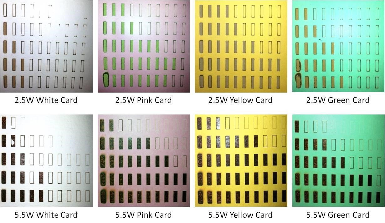
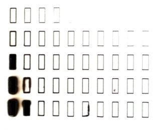
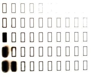
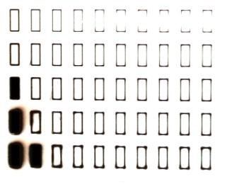
Here are some samples of my results.
The ones using the 2.5W Laser have a feed rate per column starting at 100, incrementing by 100 for each column and ending at 1000, The Laser power for each row starting at the top is 125, 250,500,750 lastly 1000.
The ones using the 5.5W Laser have a feed rate per column starting at 100, incrementing by 100 for each column and ending at 1000, The Laser power for each row starting at the top is 150, incrementing by 150 for each row and ending at 750. The box size is also different.
No reason for the change apart from an evolution of the generating spreadsheet and I really didn’t want to go back and redo the earlier tests. The purpose if this is to examine the differences different materials make and to show me what difference various speed and feed rates make!
There is one last difference between the two sets. The acceleration values in the router for the 2.5W are the default of 30mm/sec2, by the time I performed the tests with the 5.5W I had already changed the acceleration to 5,000 mm/sec2. (See later)
NOTE: The background from the cut out holes has nothing to do with anything, it’s just the top of my desk or whatever was underneath when the photo was taken!
Unless you have exactly the same card and paper as I used your results will be different. Also not a very good comparison between the 2.5W and 5.5W Lasers as the settings are different and the box sizes are different.
But as something to show how the material used affects things, quite useful I think. This is meant to give me a starting position, more fine tuning will be needed depending on the specific material and if I am trying to cut, engrave or whatever.
But my rough conclusions are:
- The 5.5W laser is a bit over twice as powerful as the 2.5W one. (Bet you didn’t see that one coming!).
- Very slow speeds at high power are bad (At least for paper), leaving the paper burning and making thick lines. Unfortunately high feed rates and low power are also bad as they will barely scorch the paper if at all.
- The material used, its colour, being shiny, … makes a difference.
- Once the paper has started to burn it will continue to do so, making the cut easier, but if the power is not high enough or the speed is too fast it may just leave the surface untouched.
- The spoil-board matters, my first attempts using a piece of dry pine charred the spoil-board through the paper at the higher laser powers and slower speeds, which then set fire to the paper.
- My white plastic Spoilboard which seemed to be ideal as it didn’t burn will melt!
My first attempt using the 2.5W laser from a jpeg, engraved on .7mm white faced card using the values derived from my earlier tests. I upped the max speed to 500mm/min as I wanted to show the greyscale, it worked well (At least I think so).
Maintenance
Not a lot needed, but as the processes of using the laser will generate smoke and soot every so often clean the outside of the focussing lens. I use a cotton bud dampened with window cleaner, then use the other end to polish it dry. Repeat until the cotton bud comes out clean.
Tidying up the lines
From Grbl Configuration Page:
Finally, tune your settings to get close to your desired or max performance…… Tweak your $12x acceleration and $11x max rate settings to improve performance. Set to no greater than 80% of absolute max to account for inertia, cutting forces, and motor torque reductions with speed.
Possibly expect a posting in this series of Fine Tuning GRBL Settings sometime in the future.
But this makes such a difference I thought I would include it here.
I noticed that the ends of lines are cut more heavily, ending in a thicker line followed by a burnt dot, some of the box tests engrave the corners but not the lines – not what I expected or wanted, and so I looked for a reason. (You can only see this on the 2.5W laser boxes as I had changed the acceleration already before making the 5.5W tests)
$120, $121, $122 – [X,Y,Z] Acceleration, mm/sec2
This sets the axes acceleration parameters in mm/second/second. Simplistically, a lower value makes Grbl ease slower into motion, while a higher value yields tighter moves and reaches the desired feed rates much quicker. Much like the max rate setting, each axis has its own acceleration value and are independent of each other. This means that a multi-axis motion will only accelerate as quickly as the lowest contributing axis can.
Again, like the max rate setting, the simplest way to determine the values for this setting is to individually test each axis with slowly increasing values until the motor stalls. Then finalize your acceleration setting with a value 10-20% below this absolute max value. This should account for wear, friction, and mass inertia. We highly recommend that you dry test some G-code programs with your new settings before committing to them. Sometimes the loading on your machine is different when moving in all axes together.
The default values on my machine are 30mm/sec/sec for all of them.
Consider this:
| Time taken, in seconds, to achieve full feed rate starting from zero | |||||||||
| Feed Rate | Acceleration (mm/sec/sec) | ||||||||
| (mm/min) | (mm/sec) | 30 | 50 | 100 | 500 | 1,000 | 5,000 | 10,000 | 100,000 |
| 1000 | 16.67 | 0.556 | 0.333 | 0.167 | 0.033 | 0.017 | 0.003 | 0.002 | 0.000 |
| 750 | 12.50 | 0.417 | 0.250 | 0.125 | 0.025 | 0.013 | 0.003 | 0.001 | 0.000 |
| 500 | 8.33 | 0.278 | 0.167 | 0.083 | 0.017 | 0.008 | 0.002 | 0.001 | 0.000 |
| 250 | 4.17 | 0.139 | 0.083 | 0.042 | 0.008 | 0.004 | 0.001 | 0.000 | 0.000 |
| 75 | 1.25 | 0.042 | 0.025 | 0.013 | 0.003 | 0.001 | 0.000 | 0.000 | 0.000 |
This shows the effect of acceleration values on the time for the router to get up to speed depending on the feed rate assuming the spindle or laser is at rest to start with. So if you start a line from rest at a feed rate of 1000 it will take over ½ a second before it is at full speed. No wonder the burn is heavier!
Grbl does include compensation for this when Laser mode is set, but IMHO it doesn’t work very well.
These settings ONLY determine the acceleration of the spindle, letting the spindle reach its specified rotational speed is totally separate. Consider making an ‘air cut’ for a few mm before encountering the stock, the spindle would already be rotating at full speed and moving at the specified speed before encountering the stock – no problem there.
Remember the board could be trying to move a big spindle motor, for bigger machines maybe 5Hp rather than the little one we have and 5 horses weigh a lot, also a much bigger and heavier bed, larger stock….!
Apart from how fast an axis can be accelerated by its stepper motor this should have no effect on anything else. It should be noted that unless you are only moving the spindle along in a single axis at a time the acceleration values on all the axes it is moving in will affect each other. Imagine a 45˚ movement on X and Y, the spindle can only be accelerated as fast as the lower of the X and Y accelerations to keep the line straight.
One last thought is that the masses of the spindle and mounting, the bed+clamps and stock probably will be different so affecting the acceleration, just as on the Z axis when moving up has to lift the mass of the spindle motor and mount, going down should be easier.
I started by setting the X axis acceleration from the default of 30 mm/Sec2 to 50. The instructions say to listen for the stepper motor stalling when it is being asked to do too much work. Well apart from possibly an initial click, which I surmised came from the backlash nut moving slightly, no problem.
Well to cut a long story short I rapidly reached an acceleration value of 100,000mm/Sec2 on the X axis without any visible or audible evidence of stalling the stepper motor (with the SainSmart 5.5W laser fitted). TOO EASY! All things that are too easy are wrong 99.99% of the time! Perhaps the stepper motors stalling under acceleration is not easily determined by eye or ear? And I cannot see why a default value of 30 should be set if a possible correct value could be 100,000! (but then I remembered this is a small machine and default settings should always be conservative)
So back to the TracingTest Gcode generator spreadsheet.
Thought I would engrave a series of shapes like this:

20mm across and high, it mixes horizontal, vertical, diagonal and circle movements, G0 (rapid non cutting movements) and G1 movements so it should be fairly easy to see if the stepper motors are stalling and missing steps by the lines becoming misaligned. NOTE: The circle is only approximately aligned with the lines, nowadays even thinking about trigonometry tends to drive me to drink! So let the intersection of the diagonals AC and BD define the midpoint of the circle…….
A series of these cannot placed in a single .nc file as Grbl objects (quite rightly) to changing parameters such as $120 in the middle of a GCode file. So the file ‘LaserAccelerationTest-xxx.nc’ produced from the spreadsheet just sets the acceleration ($120-122) values to xxx and draws a single shape, then positions the laser ready to start another one to its right. So if you want your own values in the .nc file for your own tests either edit one of the .nc files to change the $120-122 lines between each box or delete these lines completely and change the settings before each run manually using console commands.
So:
- Set the WCS origin position (Click the Globe Icon in LaserGRBL)
- Run the program
- Repeat
The WCS origin for this is the bottom left. Any missed steps will be cumulative and should be easily visible (well not 1 or 2 steps but you know what I mean).
I ran a set of samples at varying accelerations, this will only test the X and Y axes but that should be a good start. To stress things further I ran the tests with a 3.15kg weight (OK it was a wine box but it was not harmed during this experiment) on the bed. As far as acceleration goes this should put a greater strain on the Y axis.
These are the results: From top left the acceleration values are 30,60,120,200,500 then on the second row 750, 1,000 5,000 10,000 and 100,000.
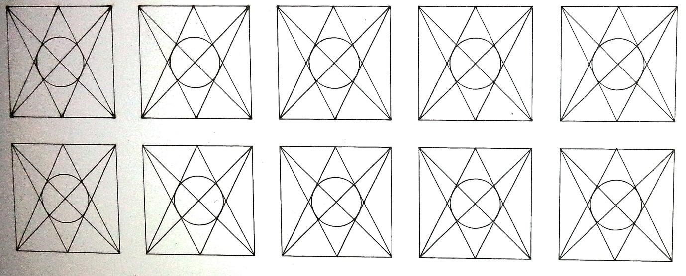
The tests were run using a piece of 3mm card (I didn’t want it to burn through). I expected this to show up deviations first on the Y axis by trying to accelerate the mass.
So, and please excuse the photography, at the default of 30 all of the vertices are over-burnt, including the circle (which starts cutting on its middle left). At an acceleration of 500 (top right) all of this has largely disappeared and the cut is much cleaner. 5,000 sees the last vestiges of a thicker line on the left of the circle disappear, From then on no real discernible difference for this test, and I am looking at the original, not the photo!
But no misalignment of the lines which means no missed steps!
A pleasant side effect is that the job time went from 32 seconds with the acceleration set at 30mm/sec/sec to 21 seconds at 5,000mm/sec/sec.
Not at first really believing these results I reset the router and ran it again at an acceleration of 100,000 – no change. So I powered it off, disconnected left it for a few minutes and tried it again – no change.
Then I decided to run my boxes test, at 3 acceleration settings- 30(default) 500 and 100,000 mm/sec/sec
At 500 there are still some faint dots at the marginal corners, at 100,000 these have all but disappeared.
I have tested this out with the spindle motor mounted and using a couple of bits, at this point I can’t foresee any problems, but my foresight is poor, that’s why I test things!
I have set my $120-122 values to 5000 pending further investigation.
Acknowledgements
I would like to thank:
- All those involved (too many to list) in creating Grbl, releasing it as a free to use Open source project and supporting and improving it.
- Denvi for creating, improving and supporting Candle as a free to use Open source project.
- Arkypita for creating, improving and supporting LaserGRBL as a free to use Open source project.
- SainSmart Customer support for all their help and standing behind their product.
- All members of the SainSmart Genmitsu CNC Users Group on Facebook, both for answering my stupid questions, showing inspiring examples and asking questions that made me think.
- ………..
This is not intended as a definitive manual but it may help with some of the principles and techniques involved. If nothing else writing this down has clarified my understanding.
Any comments, proofreading, other ideas or discussions welcomed.
Regards
Graham Bland.