. Updated with a winners' images")
Introduction to CNC for a Total Novice
Part of a series by Graham Bland
Basic GCode for Grbl
Contents
Supported Commands and Parameters
Coordinate Systems and Origins
Common GCode commands NOT supported by Grbl
Grbl Settings – Restore and reset
Introduction
An guide to what GCode is on a Grbl based small 3 axis router, how does it work, what does it do and how to read, modify and if necessary write simple programs. It’s not intended to be a tutorial on how to write it; this is just an introduction to the basics.
There are lots and lots of tutorials, introductions and descriptions out there however they tend to be broad descriptions covering lots of different routers, including many commands unsupported by Grbl. This one is aimed specifically at users of Grbl based systems.
I strongly recommend that if you are starting out you read Introduction to CNC for a Total Novice – Getting Started first! See ‘Other files in this series’ below for where to find it.
I am producing this as a document, mainly because It is an edited series of notes I made, partly because I am tired of watching instructional videos on YouTube which play at Mach 2 and so I am constantly stopping, rewinding and re-watching. Also I have been told I have a body made for Radio, a voice most suited to the Deaf and I still haven’t worked out how to use the video camera on my phone properly.
Other files in this series
All these are in the files section of this group (https://www.facebook.com/groups/SainSmart.GenmitsuCNC/), there may be more or less as I am not going to update everything if I add a new one or remove one.
They can be found in the files section of the Facebook group by searching for ‘Introduction to CNC for a Total Novice –’ Or ‘Introduction to CNC for the Total Novice –’ Consistency has never been one of my strong points, just search for’ Introduction to CNC’ or the title you are interested in!!
| Title | Contents | Facebook link |
| – Getting Started | Introduction to the process and how to check and test your 3018. READ THIS FIRST! | https://www.facebook.com/groups/SainSmart. GenmitsuCNC/permalink/2352850398359114/ |
| – Making a Spoilboard | Example of how to cut, fix, face and engrave a 3018 Spoilboard with specific instructions for 3018-Pro and PROVer. | https://www.facebook.com/groups/SainSmart. GenmitsuCNC/permalink/2451607738483379/ |
| – Setting up a Laser | Fitting, focusing and starting out with a Blue Diode Laser on your 3018. | https://www.facebook.com/groups/SainSmart. GenmitsuCNC/permalink/2356427874668033/ |
| – Tuning Grbl Settings | Exploring and optimizing settings for your 3018 to make it faster and better. | https://www.facebook.com/groups/SainSmart. GenmitsuCNC/permalink/2373672706276883/ |
| – Spindle Speed and Laser Power | The relationship between the Spindle Speed and Laser power of your 3018 and how to set the values. | https://www.facebook.com/groups/SainSmart. GenmitsuCNC/permalink/2531618443815641/ |
| – Bits | Descriptions of what bits are and how to use them on a small router. With Tool Libraries. | https://www.facebook.com/groups/SainSmart. GenmitsuCNC/permalink/2666712616972889 |
| – Basic GCode for Grbl | Introduction to GCode on Grbl based routers plus non GCode control commands. | This File |
Versions of a lot of these along with more information and resources, yes there are other people who do this sort of thing, can be found at https://docs.sainsmart.com
Disclaimer
Yeah nowadays it has to be included, and it makes sense as I accept NO liability for anything I may say, write or think.
- I am a total novice (or was when I started out). I MAKE NO CLAIM THAT ANYTHING I SAY IS CORRECT! All this is based on searching the Internet, forum comments…. and my own experiences.
- This is based solely on the one I have, if there are variations or different versions out there I have not seen them.
- If you have and are using a Laser module, even the lowest powered is powerful enough to destroy your vision completely, and that of any pets, children, spectators etc. SO EXCLUDE THEM AND USE THE GOGGLES!
- These are power tools, sharp pieces of metal designed to cut things while rotating at high speed and throwing small bits away also at high speed. Keep everybody’s fingers out! A wood chip flying up your nose is nothing to be sneezed at, never mind in one of your eyes.
- Take account of the materials you are using and take adequate precautions, dust and ashes can be harmful.
- I work in mm. Why anyone still uses inches for design work is a mystery. But then I still think of temperatures in Fahrenheit, anything beyond 100m in miles and property plot sizes in acres!
- I have been told by lots of people that my sense of humour is at the least a bit strange. I do not apologise for it.
Any corrections, clarifications or discussion are always welcome. You can find me on the Facebook
SainSmart Genmitsu CNC Routers Group as Graham Bland. Public posts are much preferred rather than messages so others may contribute or benefit from the discussions. https://www.facebook.com/groups/SainSmart.GenmitsuCNC/
What is GCode
The router understands a set of commands called GCode (Geometric Code, first developed in the late 1950s, that’s over 60 years ago!) which control the motion, speeds etc. of the spindle allowing accurate and repeatable machining. It is defined in multiple standards
(https://en.wikipedia.org/wiki/G-code) but nobody paid much notice to the standard other than as a basic core. Manufacturers of CNC (Computer Numerically Controlled) machines used the core concepts but developed their own extensions and implementations. So nowadays it is more like a set of guidelines ultimately dependant on the specific router it is implemented on, think of it as English with a lot of dialects and not all words have exactly the same meanings, not all meanings use the same words.
GCode is a series of instructions which tells the router Left a bit, go faster, right a bit, go down, go slower….. The best analogy I have is like the instructions a human brain sends to the hands when they are turning the knobs on a 3 dimensional Etch-a-Sketch!
When your CAM software takes a tool path it has generated and turns it into GCode it passes it through a post processor specific to which GCode dialect your Router understands. Some specifically allow you to select a post processor, others rely on settings in the machine configuration but the process is the same. Selecting the wrong post processor or machine will cause problems and errors when the GCode is sent to the router.
What is Grbl?
This is the software which runs on the router motherboard; it basically takes GCode and translates it into the electrical impulses to the motors that control movements and speeds. Grbl is free to use open source software.
This guide is based on Grbl Version 1.1 (more specifically 1.1.f). At the time of writing this is the overwhelmingly common version you are likely to be using, unless you have an older controller board.
Grbl also understands commands to move the bit around, set origins, change settings… and will also report back how it is doing and what is happening. These are outside of the GCode framework but are also described in this guide.
The router receives these commands one line or block at a time over a serial communications link, normally from a PC or other device such as an offline controller. NOTE: in Grbl based systems the offline controller uses the same serial port as the USB connection, just using a different cable and socket. This is why you cannot have an offline controller and USB connection active at the same time.
When Simen Svale Skogsrud first sat down and wrote Grbl in 2009, he named it after a bigger version of a computer mouse. It’s small, useful, and doesn’t do much other than what it’s designed to do. So, if you ask him, it’s pronounced as “gerbil”.
NOTE: Grbl runs on a microprocessor which uses a number of outputs to control things like stepper motors, Spindle motors, Lasers….. It also has a number of inputs which are used for things like connecting limit switches, door switches…..
If your router Main Board either does not expose these inputs and outputs or if they are not connected to anything the use of the feature becomes irrelevant! Obvious examples are limit switches, the use of a safety door open input and coolant control output. You almost certainly don’t have the last two connected so even though Grbl supports them their use is probably irrelevant and they will do nothing. I have described these features though just in case.
GCode File Format
It’s a text file, very simple, can be displayed and edited by any text editor, the file extension can vary from .nc, .txt, .tap, .gc, ….. while the file type may be different as it’s set by the software which creates the file and recognised by the software that is going to read it the contents of the files will always be the same.
But (there’s always a but!) there are lots of standards for text files; the most important is how the end of each line is marked. Different operating systems use a different format of text files. The most common formats are Unix/Mac and Windows format. The difference is that on Unix/Mac, it’s just a LF character (\n). On Windows, it’s a sequence of two characters, CR and LF (\r\n).
Grbl recognises both but as it receives the data from the GCode sender over a serial port, it doesn’t read the files directly, however your GCode Sender or Offline controller may only recognise a specific format.
GCode Line Format
Separate from the file format, what does each line look like? A line can also be referred to as a GCode block.
When processing a line first Grbl ignores all spaces and tab characters, converts all characters to upper case and ignores any blank lines so all the following are treated identically:
- G1 X4 Y7
- G1X4Y7
- G1X4 Y 7
- g 1x 4 Y7
Commands normally consist of a letter followed by a number, for example G is a general command followed by a numerical type, 0 indicates a positional move. The number is converted from all digits until a new command letter is found so the following are treated identically:
- G1
- G01
- G01.0
- G000001
- g 0 00 1 (remember spaces are removed and letters converted to uppercase) G0001.001 would not be the same as the number is does not resolve to 1 but 1.001
Commands can (as long as they don’t share parameters or conflict with each other) be specified on the same or different lines, the order that they appear on the line is not important. Obvious conflicts would be placing a cutting move (G1) and a non cutting move (G0) on the same line, like a drill sergeant shouting place your left right foot forward. So all the following have the same effect:
- G90G20G0X1
- G20 G90 G0 X1
- X1 G20 G90 G0
- G90 G0 G20 X1
Comments
There are two types of comment in GCode, a ‘;’ indicates that the rest of the line is a comment. Comments can also be placed within brackets, only ‘(‘ and ‘)’ are supported square and curly brackets are not. The comment starts with a ‘(‘ and is ended by the first ‘)’ encountered or the end of the line.
Nested comments like (this is a (comment) and so is this) are NOT supported the first ‘)’ will terminate the comment and then the ‘and so is this)’ will be processed as normal but will generate an error as its not valid GCode. However something like ‘G0 (positioning move) X3 (move 3mm)’ is valid and will be processed as ‘G0 X3’.
Do not use the ‘;’ comment within brackets to try and comment the rest of the line out, it will be ignored as being part of the original comment!
Modal vs non modal commands
Modal commands set a mode, the mode is remembered for all subsequent commands until explicitly changed. Non modal commands apply only to the line in which they are contained and are not remembered for any subsequent lines.
For example Snnn sets the spindle speed to nnn; it is a modal command so will be remembered until changed.
So:
G1 X1 Y1 S1000
G1 X2 Y2 S1000
And
G1 X1 Y1 S1000
G1 X2 Y2
And S1000
G1 X1 Y1
G1 X2 Y2 Behave identically.
In fact the movement type G1, G0… is also a modal command so
G1 X1 Y1 S1000
X2 Y2
Will also behave identically.
When Grbl is started or reset then it sets and loads defaults for some but not all modes.
Command vs. Parameter
Some commands have parameters, some don’t. For example G0 is a movement command and uses the parameters of the new positions of the axes, Xnn Ynn and Znn. Not all have to be specified, the ones that aren’t specified will just be taken as no change. G21 sets the units used to mm and has no parameters.
You cannot have two commands on the same line which share the same parameters and cannot have multiple identical parameters on the same line as the parser gets confused and so will return an error. For example
G0 X1 G1 will create an error as it’s ambiguous to the parser as to what command the X applies to. It will also object to more than one different movement commands on the same line.
G0 X1
G1 X2
On separate lines is not ambiguous.
G0 X1 X2 will also create an error for similar reasons.
Coordinate systems
This is covered in more detail in Introduction to CNC for a Total Novice – Getting Started but is worth summarising here.
Machine Coordinates
These are the position of the machine within the machine limits. The origin of the Machine coordinates is set by the position of the spindle when the router is powered on or reset; the machine origin really has no real meaning as it is not going to be consistent.
If the router is configured to perform a homing cycle by seeking out limit switches on the axes then running a homing cycle will reset the Machine Coordinate Origin to a known and consistent point. In fact if homing is enabled the machine will be placed in an Alarm state on a power on or reset to indicate that the Machine Coordinates have not yet been set. This can be cleared by running a homing cycle or just unlocking the machine which will leave the Machine coordinates as they were but place the Machine into an Idle state.
If Homing is not configured, probably because the router does not have limit switches fitted, then the Router will just enter an Idle state.
Work System Coordinates
These set the coordinates for all your jobs. When you zero the origin before starting a job you are setting the origin of the Work Coordinates and all moves will then be based from this origin.
Grbl supports 6 separate Work System Coordinate sets (G54-G59) and the origin of these can be set separately and are saved permanently until changed, this would allow a machine to be set up with a number of fixed clamps or fixtures with a different origin set and saved for each, allowing multiple parts to be cut using the same GCode without having to set the origin manually for each, just change the Work System Coordinates in operation so activating a different Work Coordinate Origin. To use these you must have performed a homing cycle as their coordinates are based on offsets from the Machine coordinates. Using multiple WCS origins is outside the scope of this guide as 99.9% of users will never use them, they are mentioned briefly in case you encounter them.
G92 is normally used to set the current origin as an offset from the active Work System Coordinate manually. As it is set before each job it doesn’t matter if a homing cycle has been run or not. This is what the Zero axis buttons in your GCode sender will use.
Supported Commands and Parameters
Not everything that is GCode is supported within Grbl. Some are archaic, some have been introduced for 3D printers, and some are for features that Grbl does not have the capacity to execute such as automatic tool changers. Others may be supported but are for features which are just not normally found on small hobby routers such as more than 3 axes, anti clockwise spindle rotation, coolant control…..
Grbl does have a Laser Mode, this takes account of differences needed when running a Laser as opposed to a rotating spindle. When Laser Mode is enabled it changes the way some of the GCode operates. I have added notes on this where appropriate, See Introduction to CNC for a Total Novice – Setting up a Laser for more information.
A likely, but very broad, convention for a GCode file is:
- Comment header describing what the file does and how to set it up. (Normally omitted when you need to find out what bit you are supposed to use)
- Setup of basic modes. Normally set once at the top of the file but can be changed at any time. But a file is unlikely to switch from using units of mm to units of inches in the middle!
- Movements with Speeds and Feeds
- End of Program, it may just stop or more likely go somewhere first.
NOTE: In the tables below a default mode for a modal command is the one in operation after a power on or reset of the router Main Board.
Line Numbers
| Command | Modal | Description | Parameters |
| Nnnnn | No | Sets the line number for this line as nnnn. | None |
These are not normally used but you may see them, they are ignored by Grbl.
Measurement units
| Command | Modal | Description | Parameters |
| G20 | Yes | All distances and positions for this line and any following lines are in Inches | None |
| G21 | Default | All distances and positions for this line and any following lines are in mm | None |
Note: What units Grbl uses to report positions etc. back to the GCode sender is set by a Grbl parameter ($13) and will be unaffected by these commands.
Distance mode
| Command | Modal | Description | Parameters |
| G90 | Default | All distances and positions for this line and any following lines are Absolute values measured from the current origin. | None |
| G91 | Yes | All distances and positions for this line and any following lines are Relative values from the current position. | None |
Plane selection
| Command | Modal | Description | Parameters |
| G17 | Default | When moving in an Arc (G2 or G3) the Arc is drawn in the XY plane (horizontal) this is the normal usage. | None |
| G18 | Yes | When moving in an Arc (G2 or G3) the Arc is drawn in the ZX plane | None |
| G19 | Yes | When moving in an Arc (G2 or G3) the Arc is drawn in the YZ plane | None |
Used only for drawing Arcs, ZX and YZ planes are outside of the scope for this guide.
Feed Rate Mode
| Command | Modal | Description | Parameters |
| G93 | Yes | Inverse time mode, a motion should be completed in 1/F minutes The F parameter must appear on every G1 G2 or G3 command, the default setting will not be used. | None |
| G94 | Default | Units per min mode, the current F rate specifies the speed. The actual units depend on the G21 / G20 mode. | None |
G94 is the default and ‘normal’ mode, you are unlikely to see G93, but it is possible.
Feed
| Command | Modal | Description | Parameters |
| Fnnnn | Yes | nnnn is the feed rate in Units per min, the units are determined by the current G20/G21 mode, inches or mm. | None |
If the Feed rate specified exceeds the parameter value set in the Grbl $110, $111 and $112 settings for Maximum feed rate on each axis the parameter value will be used.
Note: changing the Units by G20/G21 when a feed rate is already set without adjusting for the new units will have unintended consequences.
Note on Feed Rate and acceleration
When Grbl needs to change the direction of the spindle to start a new motion it will decelerate the spindle in each axis to allow it to change the direction cleanly and then accelerate the speed of the motion until the requested feed rate is reached.
If you are making a number of small movements for example drawing in a circle is broken down into a lot of small movements in straight lines then the requested feed rate may never be reached before it starts to decelerate before the next direction change. These movements may often be much slower in practice than the feed rate specified.
The acceleration rates used can be adjusted (with caution) by the Grbl $120-122 parameters.
Spindle Speed
| Command | Modal | Description | Parameters |
| Snnnn | Yes | nnnn is the spindle speed rate in RPM. There is no measurement of the actual spindle speed fed back to Grbl so this works out to be an approximate value. This is also used to set Laser Power if a Laser is connected. | None |
The actual spindle speed Snnnn value will be ‘adjusted’ if necessary by the Grbl $30 and $31 settings values for maximum and minimum speeds, also if the maximum speed of your spindle motor is 10,000 RPM setting a higher speed will not make it turn faster. When running a Laser the power is determined by the percentage calculated from the Grbl $30 setting for maximum Spindle speed.
Note on Spindle Speed and acceleration
When Grbl is told to change the spindle speed it will pause for a short while to allow the spindle motor to reach the new speed before continuing, this cannot be adjusted. When Laser mode is enabled these pauses are not used as the change in Laser power will be nearly instantaneous and pausing would result in over burning at that point.
Spindle Control
| Command | Modal | Description | Parameters |
| M3 | No | Starts the spindle spinning clockwise at the speed set by the current Snnn value. In Laser mode sets Constant power. | None |
| M4 | No | As M3 but sets the spindle spinning counter-clockwise but the spindle motor control circuits can’t normally handle reversing the polarity of the spindle motor. In Laser Mode sets Dynamic power. | None |
| M5 | No | Stop the Spindle rotating; the current Snnnn speed will retained. | None |
Motion – Lines
| Command | Modal | Description | Parameters |
| G0 | Default | Rapid positioning without cutting in a straight line to the position set by the axes parameters. Often called a rapid move. It is up to you to make sure it’s not actually cutting anything and set the desired feed rate. When in Laser mode the Laser will be turned off to avoid leaving unwanted lines. If using a spindle it will still rotate. | X Y Z |
| G1 | Yes | A cutting move in a straight line to the position set by the axes parameters. | X Y Z |
| G53 | No | Use the position set in machine coordinates rather than WCS coordinates, i.e. G53 G0 X-10 Y-10 would perform a rapid move to the machine coordinates of X -10 Y-10 with Z being left unchanged. All positions are absolute; the G91 relative coordinate mode is ignored. If G0 or G1 is omitted the last motion mode will be used. If it’s not G0 or G1 an error will be returned. | X Y Z |
The Modal description refers to the cutting mode which is remembered, subsequent commands using the same mode can just be the X Y Z parameters, the previous G mode will be applied.
Motion – Arcs
| Command | Modal | Description | Parameters |
| G2 | Yes | Clockwise arc mode. The interpreter will cut an arc or circle from the current position to the destination using the specified radius (R) or centre (IJK location) in a clockwise direction. I J and K are relative offsets from the current position to set the centre point of the arc (I=X J=Y and K=Z) R is just the radius. | X Y and I J K or R |
| G3 | Yes | As G2 but the arc is drawn in an anti-clockwise direction. | X Y and I J K or R |
| G91.1 | Default | Sets Arc incremental position mode, I J and K will always be incremental coordinates regardless of the G90 G91 mode. There is also a G90.1 command to set them back to absolute coordinates but it is not supported by Grbl with incremental I J K coordinates being the only mode supported. This is one of those commands that is just recognised to prevent errors being generated but does nothing. |
How to draw an arc
There are only 8 basic options! Well as long as the arc is drawn in the XY plane that is.
Two sets of 4 options each are for clockwise and anti-clockwise arcs, within each set using relative or absolute coordinates leaves 2 basic options, specifying the Arc by the use of the R parameter or the IJK parameters I J K correspond to the Z Y and X axes for setting the location of the centre point of the arc.
All these examples are using relative coordinates (G91 mode), Absolute coordinate mode (G90) can be used but that would only affect the X Y end point coordinates which would just have to be translated into the absolute values, The I J and K coordinates in Grbl are always relative to the starting position and R is just a value.
The principles of drawing an arc are simple; It’s only the practice that is complex!
- It starts at the current location
- The direction the arc is drawn in is specified by G2 or G3
- The arc has a fixed radius
- The location of the centre point of the arc is specified by either stating the radius (R) OR by the always incremental coordinates of the centre point (I J K) from the starting position. You cannot use any of IJK and R in the same arc command.
- The arc stops when the XYZ coordinates in the G2/3 command is reached. If these are the same as the starting position a full circle will be drawn.
- Two X Y Z parameter values must be specified corresponding to the axis plane even if they are zero.
- Some implementations of GCode support a P parameter for arcs to specify the number of rotations to be made, Grbl does not.
Arc Examples
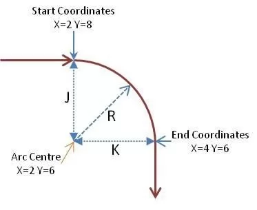 A simple arc to give a rounded corner as in the picture.
The GCode using IJK would be G2 I0 J-2 K0 X2 Y-2
The GCode using R would be G2 R2 X2 Y-2
Stopping the Arc using XY coordinates can cause problems, what if the Arc never crosses the end coordinates? Well you get errors at best, unexpected results at the worst!
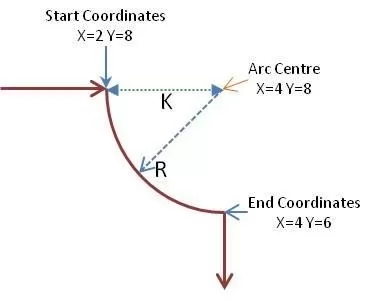 What if this was the desired result, very similar but totally different. The cut is going to be anti-clockwise and the centre point of the arc is different.
The GCode using IJK would be G3 J0 K2 X2 Y-2
The GCode using R would be
G3 R2 X2 Y-2
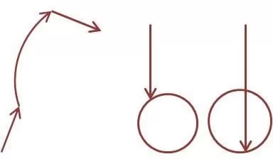 But what about?
The right two cannot be specified using just an R coordinate, they would have to be specified using IJK coordinates. This is normally true of any full circle as the end point is the same as the start point and so no information can be gleaned by Grbl as to how the circle should be drawn.
As for the one on the left unfortunately I am writing this on a Thursday, I don’t do maths on Thursdays! If you require more information there are plenty of tutorials available online.
Probing
| Command | Modal | Description | Parameters |
| G38.2 | No | Probe towards the stock, stop when contact is made, signal an error on a failure. The axis signifies the direction to move in and how far to move before a no contact error is generated i.e. G38.2 Z-10 will move the Z axis down by 10 units (mm or inches as set by G20-21) at the current Feed rate and stop when a probe contact is detected or return an error if no contact is detected within 10 units of movement. | X Y Z |
| G38.3 | No | As G38.2 but no error is returned if contact is not detected. | X Y Z |
| G38.4 | No | As G38.2 but move away from the point of contact and stop on a loss of contact. | X Y Z |
| G38.5 | No | As G38.3 but move away from the point of contact and stop on a loss of contact. | X Y Z |
Normally used for a Z probe to set the zero point of the tool tip using G38.2 but can be used on any axis, not normally found within GCode files. At the end of the probe command the current coordinates can be used to set other values such as the zero position in Work Coordinate Systems.
Coordinate Systems and Origins
Notes on Machine coordinates
These are maintained by the machine and define the position in the XYZ workspace of the machine.
When powered on or reset these are set to all zero, the machine at this point has no idea where it is in its 3 dimensional space. The only way to tell it where it is is to perform a homing cycle which requires it to be fitted with limit switches and be set up correctly.
A homing cycle will move the machine to the home position by touching a limit switch on each axis in turn which ones are used depends on the setup parameters for the homing cycle.
Once Homing is successful the machine coordinates will be set to reflect what should be an accurate and repeatable position in the machines workspace. This will not be Zero, by default Grbl uses what is known as a negative space, the coordinates of the home position will be negative. On my PROVer I have changed these values from the defaults! The default values were $3=
The values you will see depend on the homing parameters which are $23 which sets the corner into which the machine will home (mine is Top Front Left or $23=3), the values of $130 to $132 which set the maximum machine travel (These don’t have to be exact for homing but also set the rough limits of travel the machine will move before reporting a homing error(GRBL will give up searching for a limit switch after 1.5x of the maximum travel distance). Mine are $130=275, $131=175, $132=40) and lastly the amount the machine should pull back from a limit switch once it has tripped which is set by $27 (Mine is $27=0.5) tell the homing cycle. All parameter distances are always in mm!
So my Machine coordinates after homing are X:-274.5 Y:-174.5 Z:-0.5
If you run the default value of $23=0 and so home to the top back left you would see machine coordinates of X:-0.5 Y:-0.5 Z:-0.5 The machine coordinates are shown at the current position which is AFTER the pull off to deactivate the limit switch, going to a machine coordinate of 0 on any axis will always activate the limit switch.
In both cases moving the Z axis down X axis to the left or Y axis to the front will change the relevant axis coordinate in a negative direction.
NOTE: If the values of $3 or $130-2 are changed these machine coordinates for the home position may change and could destroy the validity of any offsets based on them!!!
If you don’t run a homing cycle either by unlocking the machine or homing is not enabled then the machine coordinates will remain at zero for wherever the axes happened to be. This renders a lot of things which are based on machine coordinates at best useless and at worst dangerous!! But don’t worry your machine will still function perfectly as long as you understand a little of what you are doing and which GCode features should not be used.
Notes on Work Coordinates
These are the important ones for running a job, the Work Coordinate Origin is where the start of the job will be. In normal use this origin is set using G92, this is what your GCode sender will use in the set origin buttons.
To use G92 just jog the router to where you want to start the job and hit the set origin buttons accordingly.
This will set an offset position from the current coordinate position origin which in turn is based on the Machine coordinates, it sounds complex but if this is done each time it doesn’t matter what the machine coordinates are, what any offset for a work coordinate system are, it effectively says THIS IS ZERO! Regardless of any values anything other setting may have.
| Command | Modal | Description | Parameters |
| G10 L2 | No | Sets the offset for a saved origin using absolute machine coordinates. P determines the coordinate system changed, 0 being the currently active saved origin, 1-6 specifying G54 to 59 respectively. The X Y and Z values set the relevant offset. The new values will be permanently saved until changed. | P X Y Z |
| G10 L20 | No | As G10 L2 but the XYZ parameters are offsets from the current position. | P X Y Z |
| G54 | Default | Activate the relevant saved origin and apply the offset position set for it. G54 is the default saved origin. | |
| G55-59 | Yes | As for G54 but activates a different saved position | |
| G92 | Yes | Sets the current point to the coordinates you want, normally used to set an origin point of zero, commonly known as the home position. G92 X0 Y0 Z0 sets the current point as the zero point, G92 Z-14 is commonly used to set the Z axis origin to zero in Z-Probing where 14 would be the thickness of the Z probe base with the current Z position at its top. If an axis parameter is omitted it is left unchanged. Setting the XY origin is normally achieved by jogging the spindle to the desired position and sending a G92 X0 Y0 although offsets from the current position can be used. The positions override any previously set values. The new values will be permanently saved until changed. | X Y Z |
| G92.1 | Yes | Reset any G92 offsets in effect to zero and zero any saved values | |
| G92.2 | Yes | Reset any G92 offsets in effect but retain the saved values | |
| G92.3 | Yes | Restore all G92 offsets from saved values | |
| G28 | No | Go to safe position, If X Y and Z are specified the machine will make a G0 move using those coordinates according to current modes before going to the absolute saved position. NOTE: If you have not run a homing cycle or have not set the safe position this is very ‘unsafe’ to use. If no offsets have been set this will return to the Machine origin which will automatically trigger a limit switch or just be where you turned the machine on! | X Y Z |
| G28.1 | Yes | Set Safe position. Coordinates X Y Z are absolute machine coordinates. | X Y Z |
| G30 | No | Restore predefined position. Go to the saved G30 position, if parameters are specified they | X Y Z |
| Command | Modal | Description | Parameters |
| G30.1 | No | Set Predefined position. If any parameters are used they are in absolute machine coordinates and a rapid G0 move to that position will be performed before the coordinates are saved. If no parameters are specified the current position is stored. Storage is persistent and the values will be saved until they are specifically changed. | X Y Z |
Stop and Pause (or Dwell)
| Command | Modal | Description | Parameters |
| M0 | Default | Pause. This is reliant on the GCode sender to send a resume command of ‘~’ (see Later). | |
| M1 | No | As M0 but only pauses if an optional stop switch is on, referred to by Grbl as Feed Hold. You almost certainly don’t have an optional Stop switch fitted so this will do nothing (I think!). | |
| M2 | No | Program End, turns off the spindle or laser and stops the machine. | |
| M30 | No | Same as M2. | |
| G4 | No | Pause any future command execution for the time in the Pnnn parameter. In Grbl Pnnn specifies the time to pause in seconds so P0.5 delays for ½ a second. Some other systems use milliseconds as the pause time, if used unchanged this can result in VERY long pauses. | P |
Coolant Control
| Command | Modal | Description | Parameters |
| M8 | Yes | Coolant is on as a flood | |
| M9 | Default | All Coolant is off |
Grbl does support these commands and can control a coolant system. But it is highly unlikely that your small router is fitted with the necessary coolant reservoir, pump, nozzle and coolant recovery system. Normally coolant and wood don’t mix well and all the equipment needed would cost far more than the router. I have seen one case where these were re-used to control an air-assist when using a Laser though.
Miscellaneous
| Command | Modal | Description | Parameters |
| G80 | Motion Mode Cancel. Grbl does not support any of the canned cycle modes which this cancels so it does nothing | ||
| G61 | Exact Path mode. Grbl does not support any other modes. | ||
| G40 | Cutter Compensation off. Grbl does not support cutter compensation. |
These are a set of unrelated commands that won’t cause unrecognised GCode command errors but do nothing. Support seems to be included to prevent the use of them generating errors when they are just present, normally this would be in the setup area of a GCode file.
Parameters
Parameters apply to a number of commands, for example a G0 rapid move has to be told where it is going, so it takes the X Y and Z to tell it where. Normally if a parameter is allowed for the command but not specified it will be unchanged, so G0 X1 moves 1 unit on the X axis leaving the Y and Z positions unchanged.
What the parameters actually mean will depend on some modal settings such as what are the units (mm or inches) currently in operation or absolute or relative coordinates. Parameters are never Modal.
| Parameter | Description |
| X Y and Z | Set distances or positions on the X Y and Z axis respectively. |
| I J and K | Set distances or positions for G2 and G3 drawing an Arc. Correspond to the Z Y X axis respectively. These are always incremental coordinates regardless of the G90/G91 mode. |
| Parameter | Description |
| R | Specifies arc radius for G2 and G3 drawing an Arc. |
| P | A multi-purpose parameter the meaning being totally dependent on the command it is used in. |
Common GCode commands NOT supported by Grbl
Included here as they just will give you errors, if your GCode uses one of these just delete the offending lines.
| Command | Description |
| % | Start of data during file transfer. Originally used to stop the tape rewinding at the end of the program. Not supported by Grbl as it doesn’t use a tape, paper or magnetic. |
| M6 | Automatic tool change. Normally takes a Txx parameter where xx is the new tool number. Not supported by Grbl as it doesn’t support an automatic tool changer. |
Grbl States
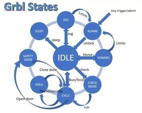 Grbl is always in a ‘State’ these affect what it will do and what commands it will accept. This is a quick summary.
NOTE: If you have an Emergency stop button fitted this normally sends the microprocessor on the Main Board into a continuous reset state; until it is released it prevents Grbl from running at all. This is instantaneous and has nothing to do with Grbl. On releasing the Emergency Stop button Grbl will be started as if it had just powered on.
| State | Description |
| Alarm | Either it has homing enabled and a homing cycle has not yet been run or an error has been detected such as a limit switch being activated. Needs a homing command or unlock before commands are accepted. |
| Idle | Waiting for commands, all commands accepted. |
| Jog | Performing a jog motion, won’t accept new commands until complete, except further Jog commands. |
| Homing | Performing a homing cycle, won’t accept new commands until complete. |
| Check | Check mode is enabled; all commands accepted but will only be parsed, not executed. |
| Cycle | Running GCode commands, all commands accepted, will return to Idle when the commands are complete. |
| Hold | A Pause is in operation, needs a resume command to continue. |
| Safety Door | The safety door switch has been activated, similar to a Hold but will resume on closing the door. You probably don’t have a safety door on your machine! |
| Sleep | A sleep command has been received and executed, sometimes used at the end of a job. Needs a reset or power cycle to continue. |
Grbl Error codes
When Grbl receives a command it will examine it, check it and return either an ok or an error. If it passes then it will queue it for processing into actual movements, spindle control etc. and then be ready to process the next command.
Just because a command has been checked and an ok sent to the GCode sender does not mean it has been executed or is complete. For example a G21 G0 X10 F0.01 says move the x axis 10mm to the right at a federate of 1 hundredth of a mm per minute, this would take 16 hours and 40 minutes before it was complete! The GCode is perfectly valid so an ok would be returned and
following commands would be processed and queued. But if Grbl was capable of thought it might be thinking
‘Stupid User!’
| Code | Description |
| 1 | G-code words consist of a letter and a value. Letter was not found. |
| 2 | Missing the expected G-code word value or numeric value format is not valid. |
| 3 | Grbl ‘$’ system command was not recognized or supported. |
| 4 | Negative value received for an expected positive value. |
| 5 | Homing cycle failure. Homing is not enabled via settings. |
| 6 | Minimum step pulse time must be greater than 3usec. |
| 7 | An EEPROM read failed. Auto-restoring affected EEPROM to default values. |
| 8 | Grbl ‘$’ command cannot be used unless Grbl is IDLE. Ensures smooth operation during a job. |
| 9 | G-code commands are locked out during alarm or jog state. |
| 10 | Soft limits cannot be enabled without homing also enabled. |
| 11 | Max characters per line exceeded. Received command line was not executed. |
| 12 | Grbl ‘$’ setting value cause the step rate to exceed the maximum supported. |
| 13 | Safety door detected as opened and door state initiated. |
| 14 | Build info or start-up line exceeded EEPROM line length limit. Line not stored. |
| 15 | Jog target exceeds machine travel. Jog command has been ignored. |
| 16 | Jog command has no ‘=’ or contains prohibited g-code. |
| 17 | Laser mode requires PWM output. |
| 20 | Unsupported or invalid g-code command found in block. |
| 21 | More than one g-code command from same modal group found in block. |
| 22 | Feed rate has not yet been set or is undefined. |
| 23 | G-code command in block requires an integer value. |
| 24 | More than one g-code command that requires axis words found in block. |
| 25 | Repeated g-code word found in block. |
| 26 | No axis words found in block for g-code command or current modal state which requires them. |
| 27 | Line number value is invalid. |
| 28 | G-code command is missing a required value word. |
| 29 | G59.x work coordinate systems are not supported. |
| 30 | G53 only allowed with G0 and G1 motion modes. |
| 31 | Axis words found in block when no command or current modal state uses them. |
| 32 | G2 and G3 arcs require at least one in-plane axis word. |
| 33 | Motion command target is invalid. |
| 34 | Arc radius value is invalid. |
| 35 | G2 and G3 arcs require at least one in-plane offset word. |
| 36 | Unused value words found in block. |
| 37 | G43.1 dynamic tool length offset is not assigned to configured tool length axis. |
| 38 | Tool number greater than max supported value. |
Grbl Alarm codes
Like an error code but the command has already passed through the parser without errors or the alarm has been triggered by an external event such as a limit switch being activated.
| Code | Alarm Description |
| 1 | Hard limit has been triggered. Machine position is likely lost due to sudden halt. Re-homing is highly recommended. |
| 2 | Soft limit alarm. G-code motion target exceeds machine travel. Machine position retained. Alarm may be safely unlocked. |
| 3 | Reset while in motion. Machine position is likely lost due to sudden halt. Re-homing is highly recommended. |
| Code | Alarm Description |
| 4 | Probe fail. Probe is not in the expected initial state before starting probe cycle when G38.2 and G38.3 is not triggered and G38.4 and G38.5 is triggered. |
| 5 | Probe fail. Probe did not contact the work piece within the programmed travel for G38.2 and G38.4. |
| 6 | Homing fail. The active homing cycle was reset. |
| 7 | Homing fail. Safety door was opened during homing cycle. |
| 8 | Homing fail. Pull off travel failed to clear limit switch. Try increasing pull-off setting or check wiring. |
| 9 | Homing fail. Could not find limit switch within search distances. Try increasing max travel, decreasing pull-off distance, or check wiring. |
Non GCode Commands for Grbl
Grbl accepts commands that fall outside the scope of GCode. These allow things like changing settings, jogging and status reporting.
This guide only summarises the more useful ones. Full details can be found here:
https://github.com/gnea/grbl/wiki/Grbl-v1.1-Commands#grbl–commands
Router settings
Grbl settings may be displayed by sending a ‘$$’ command to the router, individual settings can be set by sending a ’$nnn=xxx’ command where nnn is the setting number and xxx is the new value. These will only be accepted when the router is in an idle state as changing them mid program is never a good idea.
Jogging
Jogging is moving the spindle around in the X Y Z axes. You could do this by using G0 commands but the benefit of this is that jogging commands are totally independent of the parser so cannot change any modal states. Also a Jog motion can be stopped mid move.
The jog commands are normally implemented in the GCode sender by sliders or buttons for ease of use but the actual command is ‘$J=’ followed by an F value and one or more X Y Z values. Other commands can be to set units, absolute or incremental distances and setting machine coordinates.
You could type these manually but it’s probably a better idea to use the built in jogging features of your GCode sender.
Homing
This is started by sending a ‘$H’ command and is the only way to perform a homing cycle. Normally programmed into a button on the GCode sender.
Hold and resume
Sending a ‘!’ command puts the machine in to an immediate Hold state, if it is moving it will decelerate to a stop first but the Spindle will continue to rotate. If the machine was in a Jog state the current and all queued jog motions will be cancelled and the machine will return to an Idle state
Sending a ‘~’ command will resume after a ‘!’ hold command.
Check Mode
Check mode is toggled on and off by sending a ‘$C’ to the router. It may well be supported by a button or check box in your GCode sender.
When in Check Mode Grbl will parse and error check each command received and return an OK or Error code for each one, but it won’t actually do anything, move any axes, start the spindle or Laser etc. As the router is not moving or waiting for movements to complete this is a very fast process and is extremely useful for checking unknown GCode files for errors. Of course this does not give any assurance that the results will be what you want, but will flag up any errors which may occur, possibly after a while of normal running.
When check mode is toggled off Grbl will perform a soft reset.
Start Up
‘$N’ controls a set of commands to display and save GCode commands which are automatically executed at start up or on a reset in MOST cases. Two lines are available and can be saved, modified or deleted. There are lots of caveats and suggested restrictions on these, check https://github.com/gnea/grbl/wiki/Grbl-v1.1-Commands#grbl–commands before using!
Reporting
There are a number of reporting commands; these commands will report on the current state of Grbl depending on the command, normally these can only be processed when Grbl is in an Idle state.
| Command | Description | Returns |
| $$ | Display Settings. The values of all Grbl settings are displayed | A list of all the values in the format of $x=nnn where x is the setting number and nnn is the value. |
| $# | View GCode Parameters. It returns the saved values (X Y Z) for the G54-59 coordinate values and the same for G28, G30 and G92 offset values plus the current Tool length offset (TLO) and the values and status of the last probe command. (the last :0 or :1 after the probe coordinates indicates if the last probe was successful or not) | [G54:4.000,0.000,0.000] [G55:4.000,6.000,7.000] [G56:0.000,0.000,0.000] [G57:0.000,0.000,0.000] [G58:0.000,0.000,0.000] [G59:0.000,0.000,0.000] [G28:1.000,2.000,0.000] [G30:4.000,6.000,0.000] [G92:0.000,0.000,0.000] [TLO:0.000] [PRB:0.000,0.000,0.000:0] |
| $G | View GCode parser state. Returns the value of each active mode. | [GC:G0 G54 G17 G21 G90 G94 M0 M5 M9 T0 S0.0 F500.0] |
| $I | View Build Info, this normally includes the Grbl version, build date and if allowed a user definable string the contents can be modified by the $I= command followed by the build options used when Grbl was compiled. | [VER:1.1f.20170801:] [OPT:V,15,128] |
| $N | View saved start up code | $N0= $N1= |
Grbl Settings – Restore and reset
| Command | Description |
| $RST=$ | Restores the $$ Grbl settings back to the defaults used when compiling Grbl. |
| $RST=# | Erases and zeros all G54-G59 work coordinate offsets and G28/30 positions stored in EEPROM. All the values displayed by the $# command |
| Command | Description |
| $RST=* | This clears and restores all of the EEPROM data used by Grbl. This includes $$ settings, $# parameters, $N start up lines, and $I build info string. |
Changes when using a Laser
If you have a bit carving things the router doesn’t turn the motor off while it’s being positioned, it should be above the stock anyway and not touching anything so it’s not necessary. However a Laser will still burn while it’s moving and will engrave lines!
If you want more detailed description of the way things work in Laser mode please look at https://github.com/gnea/grbl/wiki/Grbl-v1.1-Laser-Mode#laser-mode-operation or Introduction to CNC for a Total Novice – Setting up a Laser.
Laser Mode ($32)
When you mount a Laser change the Grbl $32 setting to 1, when you put a Spindle Motor back in change it back to $32=0
M3 and M4
M3 and M4 are GCode commands which turn the spindle motor on at the current speed, M3 turns it on in a clockwise direction, M4 turns it on in a counter clockwise direction. Not very useful for a Laser though. So it is has been modified when operating in Laser Mode.
- M3 Constant power, Laser is turned on and the laser power will stay the same regardless of how it is moving, including when it is stationary which is useful for things like focussing.
- M4 Dynamic power, Laser is turned on but the laser power is automatically adjusted based on the current speed relative to the programmed feed rate. It tries to keep the amount of energy the Laser outs out at each point on the path the same. If the Laser is not moving it will be off.
You may see an option in your Laser CAM software to select one or the other.
Grbl Parameters
Not GCode but all these affect operation of the router and the execution of the GCode by Grbl.
The default settings and values are for my SainSmart Genmitsu 3018-PRO with a Woodpecker CamXTool 3.4 main board and the SainSmart Genmitsu 3018-PROVer with a GC3D3-V2.1 Main board.
| Applies only if using Soft Limits in conjunction with limit switches | ||||
| Applies only if using limit switches | ||||
| Setting | PRO Default | PROVer Default | Description Links will take you to the relevant page for Grbl 1.1 | Range |
| $0 | 10 | 10 | Step pulse, microseconds | 3-15 ish (only the 15 is ish) |
| $1 | 25 | 25 | Step idle delay, milliseconds | 15-30 ish OR 255 |
| $2 | 0 | 0 | Step port invert, mask | Only 0-7 |
| $3 | 2 | 2 | Direction port invert, mask | Only 0-7 |
| $4 | 0 | 0 | Step enable invert, boolean | Only 0 or 1 |
| $5 | 0 | 0 | Limit pins invert, boolean | Only 0 or 1 |
| $6 | 0 | 0 | Probe pin invert, boolean | Only 0 or 1 |
| $10 | 1 | 3 | Status report, mask | Only 0-3 |
| $11 | 0.010 | 0.010 | Junction deviation, mm | 0.1 to 0.001 ish |
| $12 | 0.002 | 0.002 | Arc tolerance, mm | 0.1 to 0.001 ish |
| $13 | 0 | 0 | Report inches, boolean | Only 0 or 1 |
| $20 | 0 | 0 | Soft limits, boolean | Only 0 or 1 |
| $21 | 0 | 1 | Hard limits, boolean | Only 0 or 1 |
| $22 | 0 | 1 | Homing cycle, boolean | Only 0 or 1 |
| $23 | 0 | 3 | Homing dir invert, mask | Only 0-7 |
| $24 | 25 | 25 | Homing feed, mm/min | 10-50 ish |
| $25 | 500 | 500 | Homing seek, mm/min | 250-1500 ish |
| $26 | 250 | 250 | Homing debounce, milliseconds | 5-250 ish |
| $27 | 1.000 | 1.000 | Homing pull-off, mm | 0.5-3.5 ish |
| $30 | 1000 | 10000 | Max spindle speed, RPM | 255-15000 ish |
| $31 | 0 | 0 | Min spindle speed, RPM | 0-100 ish |
| $32 | 0 | 0 | Laser mode, boolean | 0 or 1 |
| $100 | 800 | 800 | X steps/mm | 800 or 1600** |
| $101 | 800 | 800 | Y steps/mm | 800 or 1600** |
| $102 | 800 | 800 | Z steps/mm | 800 or 1600** |
| $110 | 1000 | 2000 | X Max rate, mm/min | 500-3000 ish |
| $111 | 1000 | 2000 | Y Max rate, mm/min | 500-3000 ish |
| $112 | 600 | 600 | Z Max rate, mm/min | 500-3000 ish |
| $120 | 30 | 10 | X Acceleration, mm/sec^2 | 10-1000 ish |
| $121 | 30 | 10 | Y Acceleration, mm/sec^2 | 10-1000 ish |
| $122 | 30 | 10 | Z Acceleration, mm/sec^2 | 10-1000 ish |
| $130 | 200 | 500 | X Max travel, mm | Around your router bed size |
| $131 | 200 | 400 | Y Max travel, mm | Around your router bed size |
| $132 | 200 | 100 | Z Max travel, mm | Around your router bed size |
** These values ($100-102) will normally all be the same. If only 2 are the same set the third accordingly. Other values are possible but 800 or 1600 are overwhelmingly common for this sort of router.
This is not intended as a definitive manual but it may help with some of the principles and techniques involved. If nothing else writing this down has clarified my understanding.
My thanks to those providing numerous resources for both Grbl and GCode, far too many to mention here. But https://github.com/gnea/grbl/wiki is a good start for more detailed information.
Any comments, proofreading, other ideas or discussions welcomed.
Graham Bland.