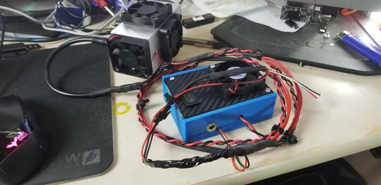
Here is the EleksMaker A3 Pro (minus the wiring to the stepper motors and laser) and is the setup we are upgrading with an Endurance 10Watt Laser Setup.
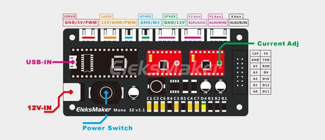
This is the pin out configuration of the EleksMana SE v3.1 control board as if you were looking downward on the circuit board. This is the current control board that ships with the EleksMaker A3, A3x, A3 Pro, and A4 models. We will be focusing on utilizing the existing Laser plug in yellow in the image. The 12v pin can supply up to 5Amps but is not necessary to get your 10 watt laser online. We will be focusing on the PWM pin on the right side of the Laser plug
Connections
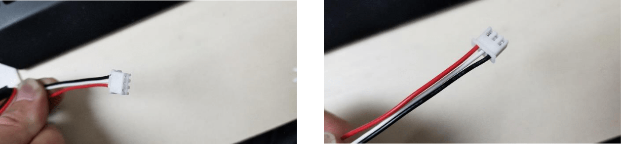
We will be utilizing the 3 pin white plug that comes with the additional cabling kit when you order the Endurance 10Watt laser. Below are two images of the extra wiring cable/plug that we will be utilizing for the setup.
The connections that will be made will be with the Black wire (PWM signal from the EleksMana) and the White wire (Ground).
Top View of TTL/PWM cable Bottom View of TTL/PWM cable
This is the Laser Control board (box) that will come with your 10Watt Laser from Endurance. At a minimum it should contain your MO1 board and the laser driver module. There are 4 wires that come out of this box. 2 are twisted together and go directly to your 10 Watt laser. The other two wires are loose and have no end connections made at this time. The loose black wire from the Laser Control board (box) is the ground wire that needs to be attached to your white wire on the 3 pin white plug above. This is your ground for your PWM circuit. The loose red wire from the Laser Control board (box) is the PWM wire that will connect to the black wire on the 3 pin white plug above.
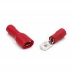
You can connect the wiring however you choose, I soldered mine together and heat shrink wrapped them or you can use male/female electrical plugs similar to this(just ensure you have the correct gauged connectors for the wiring you have):
Power
There are two additional power requirements that you will need to source. One of those is a 12V 5Amp power source and the other is a 12V 1Amp power source. The 12V 5Amp power supply will plug directly into the Laser Control Board (box) into the barrel port as seen in the picture below. The 12V 1Amp power source needs to be plugged directly into the
barrel port on the 10Watt Laser Module itself as seen in the picture to the right; this power source is only applying power to the fans on the Laser module.
Putting It All Together
Once you have your white plug wired to your Laser Control board (box) and power to your Laser Control Board (box), the laser module and your EleksMana SE board, you are ready to mount the 10 Watt laser module to your gantry and connect the 10 Watt laser module to your EleksMana SE board. It is simply plug in the white plug to the laser port on the EleksMana SE board and apply power to all devices.
Additional Information and Connections
Perform this at your own risk, I have not done extensive testing on this, however the math supports the concept and application to run it this way.
The 12V signal from the EleksMana SE board can drive the power required for your fans on the laser module. To connect those up you will need to first obtain a barrel plug with wire pigtail and connect the red wire(12V) to the positive wire on the pigtail and the white wire(Ground) to the negative wire on the pigtail; your white wire (from your 3 pin plug) will have two wires connected to it, the PWM ground and the fan ground.
You WILL need additional wiring in between the barrel plug pigtail and the 3 pin wires, ensure you have enough to stretch the length of your farthest point on your gantry setup.
To the right is the power plugs I used. They can be picked up on Amazon at https://www.amazon.com/gp/product/B07D8T756C/ref=oh_aui_detailpage_o05_s00?ie=UTF8&psc=1 I have no affiliation and receive zero payout for linking this.
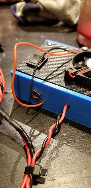
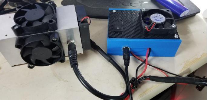
Below is my whole setup, the 3 pin wired to the PWM wires on the laser module AND utilizing the 12V line on the 3 pin to power the fans on the Laser module.