

An Endurance 15 watt (real power output) water – cooled laser with an autofocusing system. Cuts 10 mm of wood (2/5″)
About GRBL firmware – settings, parameters, values.
GRBL is a free, open-source, high-performance software for controlling the motion of machines that move, that make things, or that make things move, and will run on a straight Arduino. If the maker movement was an industry, Grbl would be the industry standard.
Most open-source 3D printers have Grbl in their hearts. It has been adapted for use in hundreds of projects including laser cutters, automatic hand writers, hole drillers, graffiti painters and oddball drawing machines. Due to its performance, simplicity and frugal hardware requirements, Grbl has grown into a little open-source phenomenon.
An open-source, embedded, high-performance g-code-parser and CNC milling controller is written in optimized C that will run on a straight Arduino https://github.com/gnea/grbl/wiki
What is Grbl?
This is the software which runs on the router motherboard; it basically takes GCode and translates it into the electrical impulses to the motors that control movements and speeds. Grbl is free to use open source software.
This guide is based on Grbl Version 1.1 (more specifically 1.1.f). At the time of writing this is the overwhelmingly common version you are likely to be using, unless you have an older controller board.
Grbl also understands commands to move the bit around, set origins, change settings… and will also report back how it is doing and what is happening. These are outside of the GCode framework but are also described in this guide.
The router receives these commands one line or block at a time over a serial communications link, normally from a PC or other device such as an offline controller. NOTE: in Grbl based systems the offline controller uses the same serial port as the USB connection, just using a different cable and socket. This is why you cannot have an offline controller and USB connection active at the same time.
When Simen Svale Skogsrud first sat down and wrote Grbl in 2009, he named it after a bigger version of a computer mouse. It’s small, useful, and doesn’t do much other than what it’s designed to do. So, if you ask him, it’s pronounced as “gerbil”.
Very necessary to know about GRBL
- It is very important to know that every single machine can operate under one or the other GRBL firmware such as: GRBL 0.8 or GRBL 0.9, or under GRBL 1.1 (different letters like GRBL 1.1H)
- As soon as you uploaded compatible GRBL (or did not upload since it has been uploaded) you need to check about GRBL configuration.
These parameters can be changed and value should be setup according to your machine
How to setup proper stepper motor (SM) parameters?
- Let’s check the stepper motor (SM) parameters
that are, the number of steps per rotation. Usually 200 (step angle 1.8°)
- We need to know the dividing coefficient of the stepper motor driver. Download the data-sheet to the driver or the controller of the CNC and observe. how it is set. Usually, as 1:8.
- Multiply 200 steps by the dividing coefficient of 8 = 1600 steps per cycle.
Now for the belt drive:
Let’s measure the tooth gear diameter of the SM
Find the length of the tooth gear (the range it covers during one cycle) L = 3.14 x D (Diameter)
E.g. D = 16 and the L = 3.14 x 16 = 50 mm. It means that the motor shaft covers a range of 50 mm per one cycle.
Dividing 1600 by 50, we get the number of steps per 1 mm = 32. We write it down to config GRBL.
For the screw measure the step of the screw.
This value shows how far the shaft will travel per one cycle of the SM. Let us assume that the step is 2 mm, it means that the shaft shifts by 2 mm per one cycle. 1600:2 = 800 steps per one cycle.
for example here is the GRBL hex file GRBL 1 1H download package with a setting that can be used on a standard Eleksmaker machine / GRBL 1.1H firmware for CNC 3018 Download GRBL_1.1H
GRBL 1.1h settings for an Eleksmaker Mana board and engraving machine 20×20 cm
Some important parameters you need to know for your Eleksmaker DIY engraving frame.
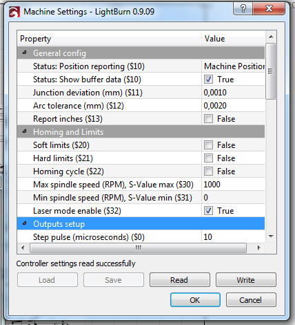
Step pulse can be different, depends on your controller and stepper motor.
For example, on high speed (>1000 mm / min) some steps on Arduino can be missing and then I increase step pulse from 3 to 10
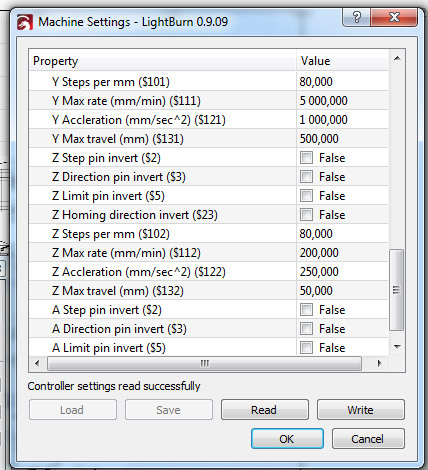
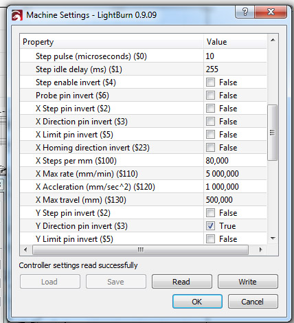
X Steps per mm is a calculated parameter. If 80 does not work, then try to make a rectangle 10×10 mm and then see if it matches the actual size or not
X Max rate mm/min is the maximum speed for your unit.
X acceleration mm / min is the acceleration when your carriage is starting to move. Can vary.
X Max travel speed – the maximum travel speed of the carriage.
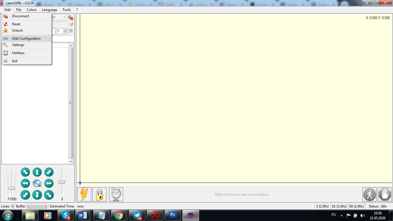
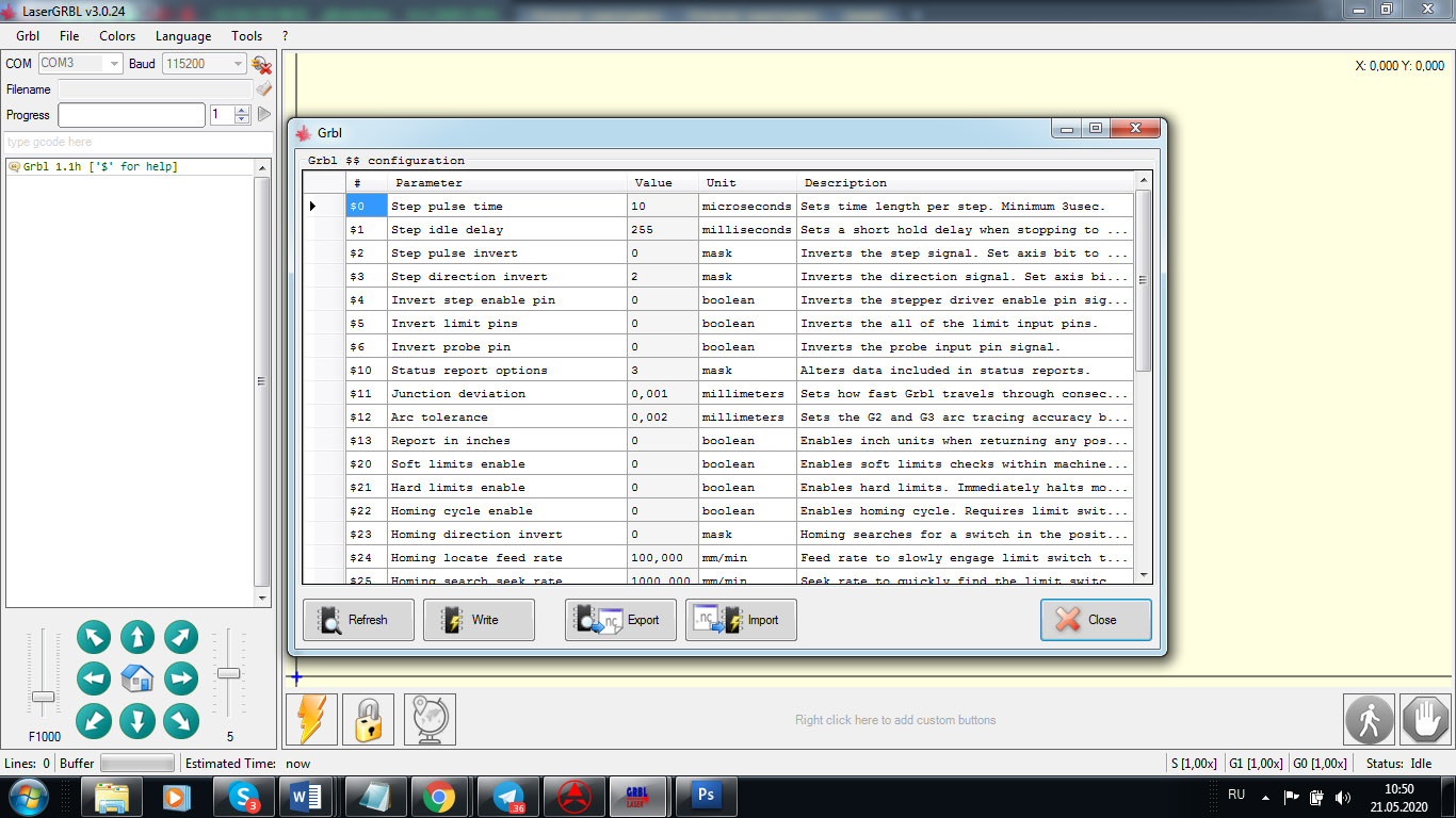
How to download and upload GRBL parameters using a LaserGRBL software
invest pin can be used depending on how you want to engrave the image and where do you want the image to start the engraving.
IT IS IMPORTANT and crucial to know that if some settings are not properly settled your machine might not work accurately
For example, if your X/Y/Z acceleration is not setup properly then your machine can engrave with black spots. It means that while it is starting the laser will burn harder comparing while it is traveling. In other words, at the first few moments while the laser is accelerating the speed with being less and the laser will burn harder.
Also if you do laser cutting or laser engraving your laser mode should be “1”, not “0”.
Keep in mind that different programs can work differently even if you have the same GRBL firmware and the same GRBL setup parameters. (That happens rarely but happens).
To start your engraving process from home you need to setup G92 X0 Y0 to make sure that your machine knows where to start.
Another tricky thing is to setup inversion for your motors. It can happen if you did not plug correctly your stepper motors into driver pins. Then you may use inversion. BUT EVEN IF YOU SETUP IT PROPERLY THE STEPPER MOTOR MIGHT HAVE AN INVERSED PINS and that will bring you to a wrong (mirrored) image engraving.
So, if you face a problem with running your machine – we can help you with that by:
- Checking your firmware (re-uploading a proper one if needed).
- Checking your GRBL parameters (changing if needed).
- Running software like LightBurn or LaserGRBL to test if your machine is working fine.
We are happy to help you!
You would need a TeamViewer to get started.
Let us know about your problem in advance (email to [email protected] or use an online chat form):
- Send us a picture of your machine.
- Send us a picture of your board.
- Describe your problem in detail.
- Offer the best time for online troubleshooting (1AM-3PM EST time)
GRBL compatible boards
2 axis
Stepper Motor Control Board Driver 2 Axis For DIY Laser Engraver Benbox GRBL
2 Axis Control
3 axis
DIY CNC 3 Axis Laser Controller Board GRBL Stepper Motor Driver Board Engraving
3 Axis GRBL CNC Router Engraving Machine USB Port CNC 3018 Control Board Card EU
Digital 3 Axis GRBL CNC Router 1.1f Engraving CNC 3018 2418 Control Board V3.4
3 Axis USB GRBL USB Driver Controller Board for Laser CNC Engraving
GRBL compatible MakerBase MKS DLC ver 2.0 board. Uploading GRBl 1.1f firmware with xLoader.
Setup GRBL parameters and settings.
Grbl States
Grbl is always in a ‘State’ these affect what it will do and what commands it will accept. This is a quick summary.
NOTE: If you have an Emergency stop button fitted this normally sends the microprocessor on the Main Board into a continuous reset state; until it is released it prevents Grbl from running at all. This is instantaneous and has nothing to do with Grbl. On releasing the Emergency Stop button Grbl will be started as if it had just powered on.
| State | Description |
| Alarm | Either it has homing enabled and a homing cycle has not yet been run or an error has been detected such as a limit switch being activated. Needs a homing command or unlock before commands are accepted. |
| Idle | Waiting for commands, all commands accepted. |
| Jog | Performing a jog motion, won’t accept new commands until complete, except further Jog commands. |
| Homing | Performing a homing cycle, won’t accept new commands until complete. |
| Check | Check mode is enabled; all commands accepted but will only be parsed, not executed. |
| Cycle | Running GCode commands, all commands accepted, will return to Idle when the commands are complete. |
| Hold | A Pause is in operation, needs a resume command to continue. |
| Safety Door | The safety door switch has been activated, similar to a Hold but will resume on closing the door. You probably don’t have a safety door on your machine! |
| Sleep | A sleep command has been received and executed, sometimes used at the end of a job. Needs a reset or power cycle to continue. |
Grbl Error codes
When Grbl receives a command it will examine it, check it and return either an ok or an error. If it passes then it will queue it for processing into actual movements, spindle control etc. and then be ready to process the next command.
Just because a command has been checked and an ok sent to the GCode sender does not mean it has been executed or is complete. For example a G21 G0 X10 F0.01 says move the x axis 10mm to the right at a federate of 1 hundredth of a mm per minute, this would take 16 hours and 40 minutes before it was complete! The GCode is perfectly valid so an ok would be returned and following commands would be processed and queued. But if Grbl was capable of thought it might be thinking ‘Stupid User!’
| Code | Description |
| 1 | G-code words consist of a letter and a value. Letter was not found. |
| 2 | Missing the expected G-code word value or numeric value format is not valid. |
| 3 | Grbl ‘$’ system command was not recognized or supported. |
| 4 | Negative value received for an expected positive value. |
| 5 | Homing cycle failure. Homing is not enabled via settings. |
| 6 | Minimum step pulse time must be greater than 3usec. |
| 7 | An EEPROM read failed. Auto-restoring affected EEPROM to default values. |
| 8 | Grbl ‘$’ command cannot be used unless Grbl is IDLE. Ensures smooth operation during a job. |
| 9 | G-code commands are locked out during alarm or jog state. |
| 10 | Soft limits cannot be enabled without homing also enabled. |
| 11 | Max characters per line exceeded. Received command line was not executed. |
| 12 | Grbl ‘$’ setting value cause the step rate to exceed the maximum supported. |
| 13 | Safety door detected as opened and door state initiated. |
| 14 | Build info or start-up line exceeded EEPROM line length limit. Line not stored. |
| 15 | Jog target exceeds machine travel. Jog command has been ignored. |
| 16 | Jog command has no ‘=’ or contains prohibited g-code. |
| 17 | Laser mode requires PWM output. |
| 20 | Unsupported or invalid g-code command found in block. |
| 21 | More than one g-code command from same modal group found in block. |
| 22 | Feed rate has not yet been set or is undefined. |
| 23 | G-code command in block requires an integer value. |
| 24 | More than one g-code command that requires axis words found in block. |
| 25 | Repeated g-code word found in block. |
| 26 | No axis words found in block for g-code command or current modal state which requires them. |
| 27 | Line number value is invalid. |
| 28 | G-code command is missing a required value word. |
| 29 | G59.x work coordinate systems are not supported. |
| 30 | G53 only allowed with G0 and G1 motion modes. |
| 31 | Axis words found in block when no command or current modal state uses them. |
| 32 | G2 and G3 arcs require at least one in-plane axis word. |
| 33 | Motion command target is invalid. |
| 34 | Arc radius value is invalid. |
| 35 | G2 and G3 arcs require at least one in-plane offset word. |
| 36 | Unused value words found in block. |
| 37 | G43.1 dynamic tool length offset is not assigned to configured tool length axis. |
| 38 | Tool number greater than max supported value. |
Grbl Alarm codes
Like an error code but the command has already passed through the parser without errors or the alarm has been triggered by an external event such as a limit switch being activated.
| Code | Alarm Description |
| 1 | Hard limit has been triggered. Machine position is likely lost due to sudden halt. Re-homing is |
| highly recommended. | |
| 2 | Soft limit alarm. G-code motion target exceeds machine travel. Machine position retained. Alarm |
| may be safely unlocked. | |
| 3 | Reset while in motion. Machine position is likely lost due to sudden halt. Re-homing is highly |
| recommended. |
We support the GRBL community!

All you need to know about G-code
Our YouTube video footages >>>
G-code examples
G-code examples and images for laser engraving and laser cutting
Endurance lasers free plugin for an Inkscape
Upgrading of a board with the GRBL firmware for laser engraving using Makerbase MKS 2 DLC board
Uploading firmware on different boards: GRBL / Marlin. Settings, parameters.