Conquering some logical levels
Using of an inverting comparator on an operational amplifier to control a CNC laser module with an inverse output
Purpose
The purpose of this small project is to ensure the ability to control the laser module in case when your CNC machine has an inverse output to control the cutter motor. For example: a signal with a level from 0 to 3.5 V turns on the engine, and with a level from 3.5 to 5 V turns it off. This problem can be solved by configuring the CNC control board of the machine, or it can be either specified in the settings of the control software, or, if this is not possible, by way of making a small module.
What we need
– An operational amplifier LM358, or an equivalent;
– Three resistors of any power: 10 K, 15 K, 33 K (100 Ohm, and a LED for testing)
– A bread board
The scheme and the principle of operation
In simplified form, a comparator is an electronic circuit that receives two analog signals at its inputs and outputs a high level signal if the signal at the non-inverting input (“+”) is greater than at the inverting (inverse) input (“-”) and а signal of a low level if the signal at the non-inverting input is less than at the inverse input. Since the control signal is inverse, we will feed it to the inverting input, and the reference voltage to the non-inverting input through a resistive voltage divider.
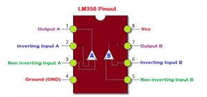
Operational amplifiers are very often used as comparators, and we will use an LM358. It has two operational amplifiers, but we will need only one. The scheme consists of 3 parts and is very simple:
Its main elements are: an operational amplifier and a voltage divider made by resistors R2, R3, which form the reference voltage.
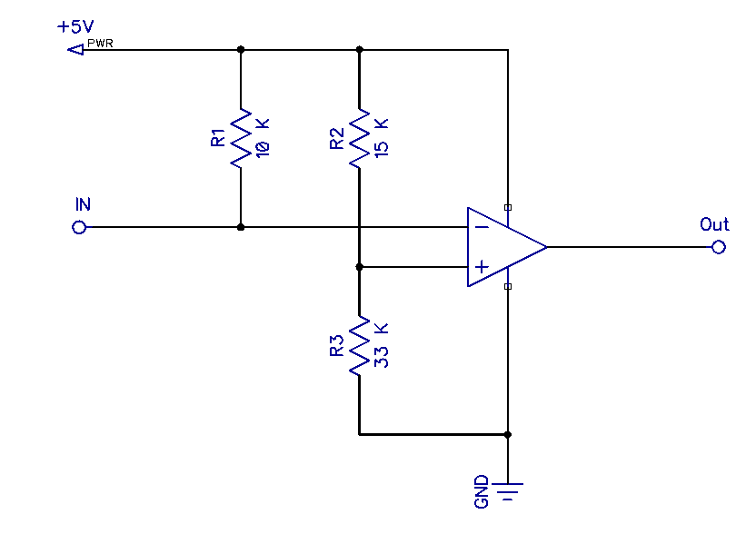
When the signal voltage at the inverting input exceeds the reference voltage at the non-inverting input, the output of the op-amp will be 0 V, otherwise – the output voltage will be almost equal to the power supply voltage, (5 V).
The magnitude of the reference voltage can be calculated by the formula:
Vref = VccR2 + R3R3
With current component ratings, it will be:
Vref = 515000 + 3300033000 = 1.04e-4 33000 = 3.43 V
This sheme can be recalculated for a different power supply voltage and reference voltage.
The operation of the device can be viewed on the video; an LED connected through a 100-Ohm current-limiting resistor is used as the load. On the right is a regulated power supply set at 5 V. The signal to the input of the device is fed through an adjustable DC-DC converter, its value is displayed on the multimeter on the left. As you can see, when the input voltage drops below the threshold level, the LED lights up, and when it is exceeded, it goes out.
| Typical values for CMOS and TTL levels | |||
| Vcc | 3.3 V | 5 V | 12 V |
| R2 | 27 K | 51 K | 130 K |
| R3 | 15 K | 15 K | 13 K |
https://drive.google.com/file/d/1Fj11Tfh7fcsjp_LpJmRTGk3nVz9vhE2v/view?usp=sharing
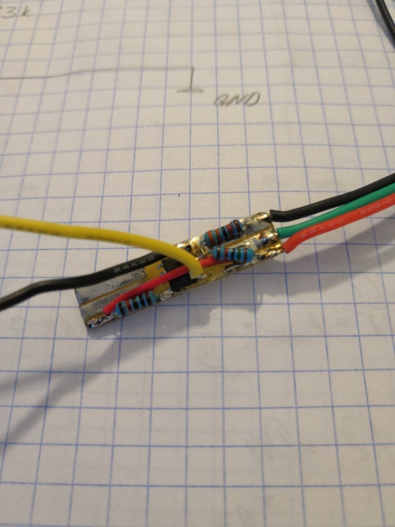
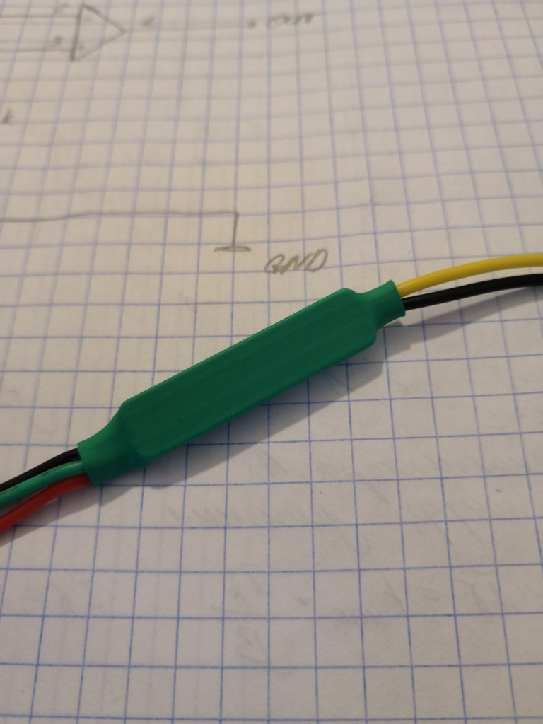
Structurally, the board is framed on a one-sided, foil-clad glass fiber laminate by surface mounting and has an elongated profile, this allows it to be placed in a heat shrinkable tube, providing a structurally complete look of the device.