
T2Laser laser engraving software
Getting started with T2laser software. How to prepare the image for laser cutting or laser engraving
If you have any problems with T2Laser – email Zax
Full guide T2Laser laser engraving
key features are:
- The intelligent algorithm that allows creating an optimized G-code for photos, images and line art.
- Grayscale engraving.
- Raster-to-vector conversion.
- Different filling options (horizontal, vertical, diagonal and cross-hatching).
- Z- or rotary axis machines support.
- Size changing, rotation and mirroring of vector files.
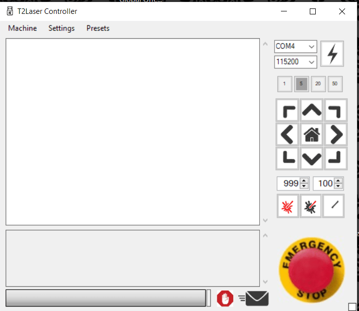
First start of the program
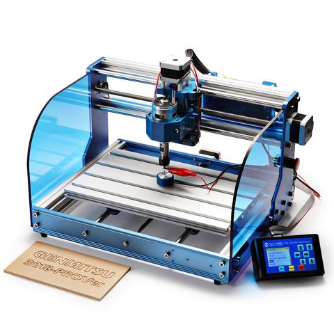
At the first start of the program, we configured to work with our machine. We used Sain Smart 3018-PROVer in the GRBL 1.1h firmware with the Endurance laser beam combiner system.
After connecting the machine we had to select a port. Then it identified the firmware and set the necessary parameters.
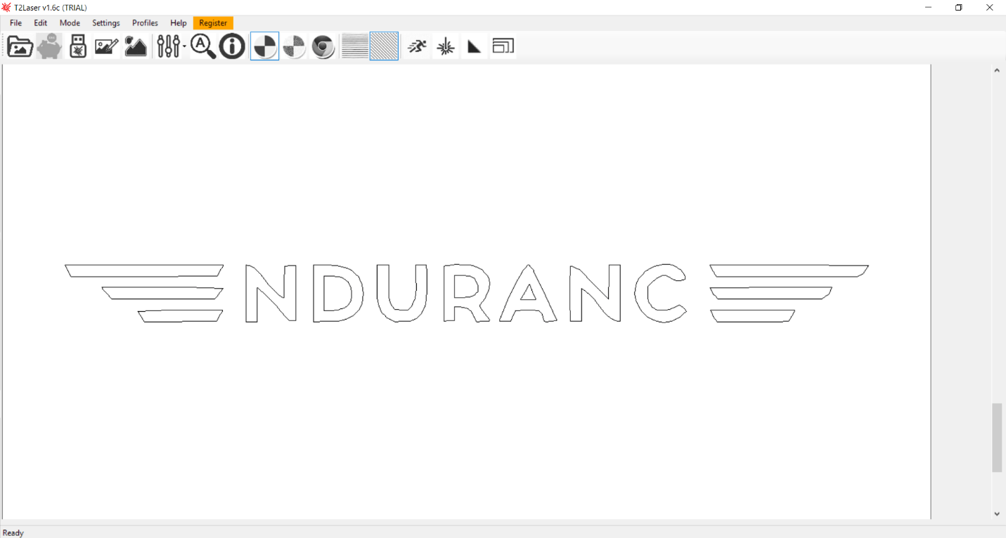
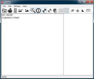
Main menu
After the image import, it is possible to convert the image to a vector file or go on working with a raster image.
All basic operation icons are displayed on the top panel.
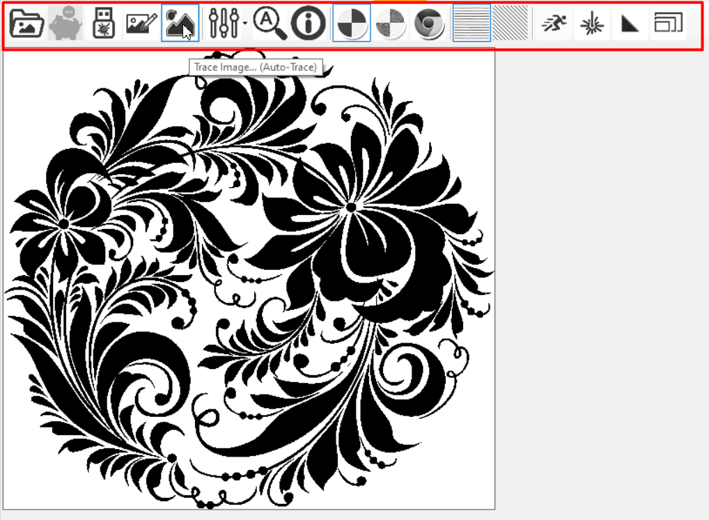
As for image tracing, there are not many options. It is possible to automatically trace the entire image or manually select the elements you need to trace. You cannot select tracing parameters and in the case of an error there is no way to manually move any element. When selecting elements for tracing manually you cannot choose to remove any of them.
Besides, because of the trial version restrictions, it is hard to get a better sense of the program. Without a license you can use it only for 15 minutes, then the program shuts down and you have to start it all over again.
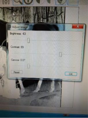
The next icon serves for making the image ready for engraving.
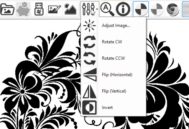
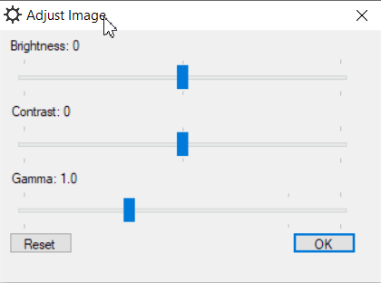
Here you can adjust brightness, contrast, gamma as well as rotate, mirror or invert the image. This set of options might be enough for simple types of work.
Then, we can select an engraving method:

- black-and-white
- Dithered
- grayscale
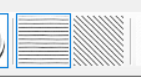
Filling (hatching) options
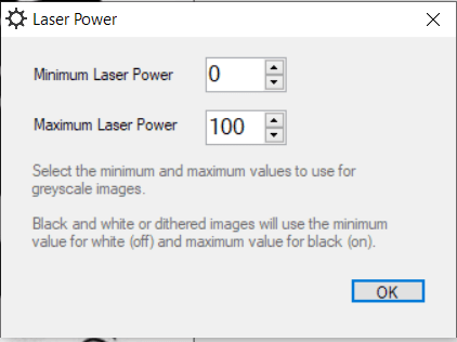
Laser power options

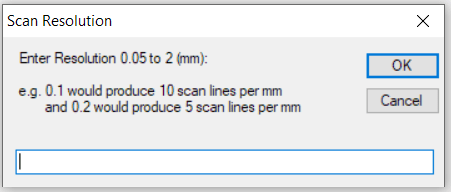
Scan (hatching) line density

The last icon on the panel serves to change the image size.

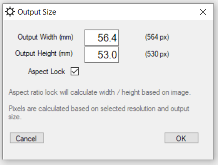
So, with this set of options, you can handle very simple tasks. All these parameters are easy to access but inconvenient to change. For instance, to adjust the size you need to open a special window each time and enter numerical values.
On the plus side
- Grayscale engraving
Three engraving options make it possible to work with a great variety of materials and images, including photos.
- Converse raster images to vector ones.
There’s also an option of raster image tracing, though not a very good one. Still, it might help when tracing of simple logos is needed.
- There is also a wide choice of filling options (horizontal, vertical, diagonal, and crosshatching).
For the implementation of certain artistic ideas, you might need diagonal engraving.
- Support of machines with Z- and rotation axes.
Thus, to engrave a drinking glass you need a rotation axis. Since this program supports the operation of the rotation axis, you can install it.
On the minus side
- Modest capabilities of vector file editing.
- If the laser hits limiting devices the machine stops. To resume work you need to close the program, manually move off the laser and re-run the program.
- There is only an AutoZoom option.
You cannot enlarge an image as much as you need. AutoZoom adjusts its size to the size of the screen.
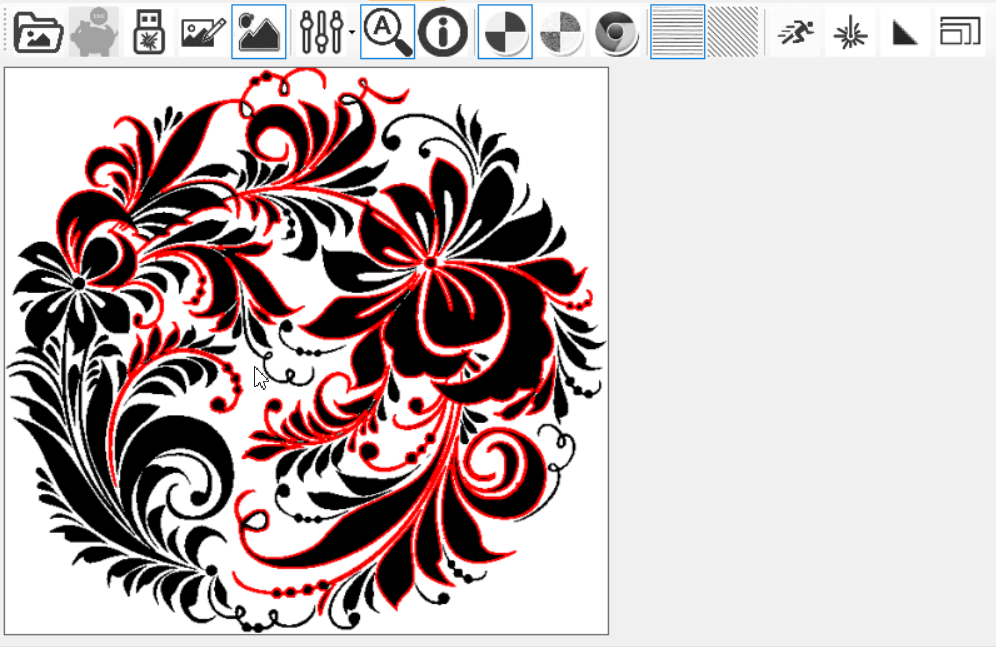
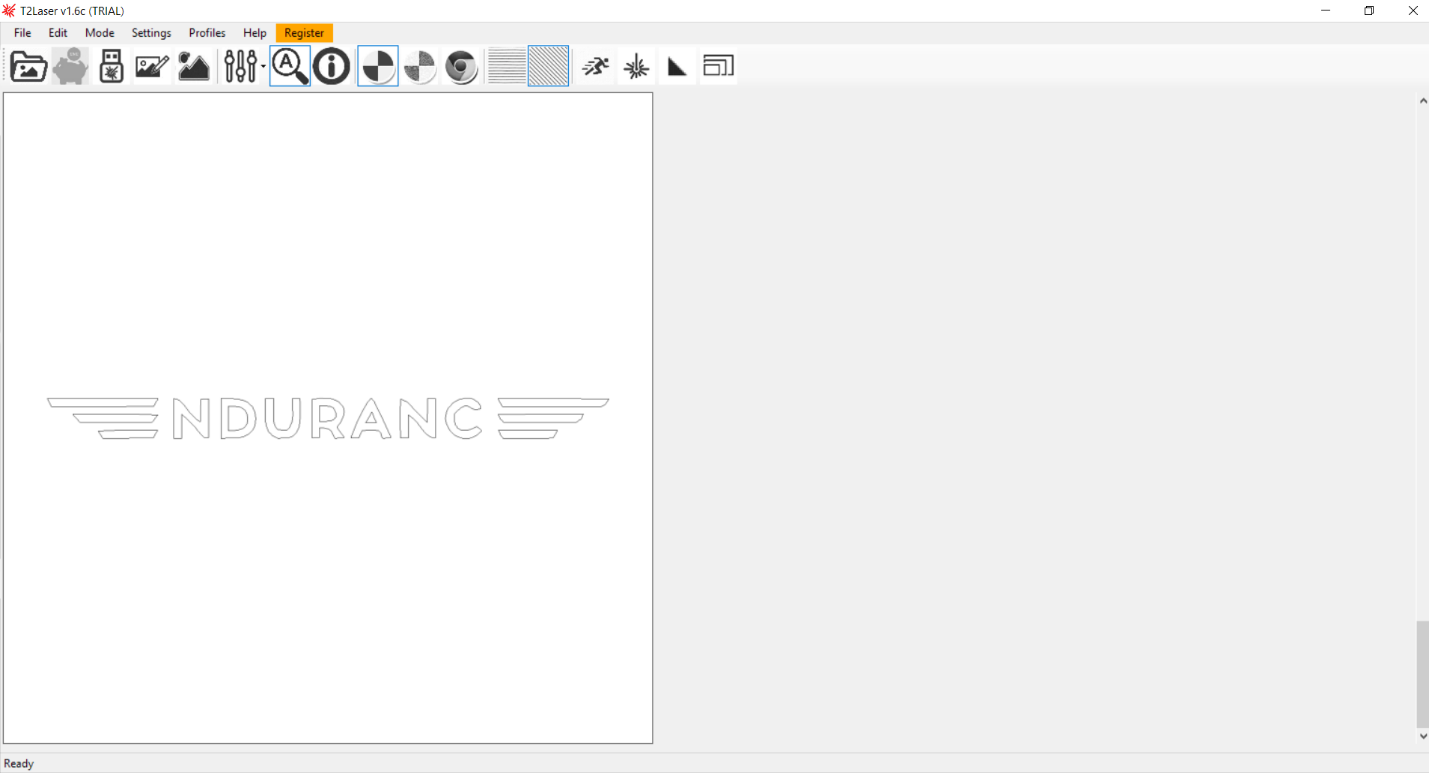
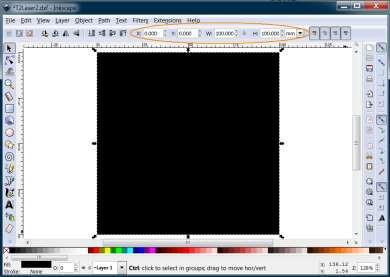
Fig.1 – An image immediately after import.
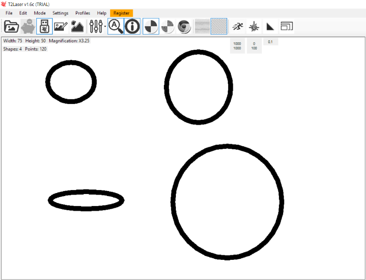
The same image after AutoZooming.
- It’s impossible to set different modes of operation for a number of objects separately. That is why you cannot cut the image immediately after it has been engraved.
At the same time in most programs, you can place objects on different layers and assign certain engraving or cutting parameters to each layer.
- The images that you see in the working area differ from those that you will get in reality.
- A limited set of the Sketch options.
Not possible to:
– fill an outline pattern,
– combine patterns,
– change the outline of the sketched image.
To make sketches you need to open a separate window where imported images are not displayed. That is why you cannot make an outline for image cutting.
- Every parameter has its own window, so if you need to change anything or just to have a look at it you need to open the window of this particular parameter.
A real customer experience with T2laser engraving/cutting software
So a little about myself before I get into the manual for T2Laser, With a Laseraxe system.
My daytime job is working on LRV’s (Light Rail Vehicles), in the evenings I do a lot of airbrushing, vinyl plotter for decals/stencils, and used to do a lot of wood burning by hand, which rarely happens since getting this system up and running.
My experience with Laseraxe did not start off well, their program would not work with my system at all, I was not able to read the screen due to it being stuck in another language, after emailing Laseraxe multiple times and never receiving an answer. I tried Lightburn, and T2Laser, I liked low learning curve with T2 so that is the program I picked.
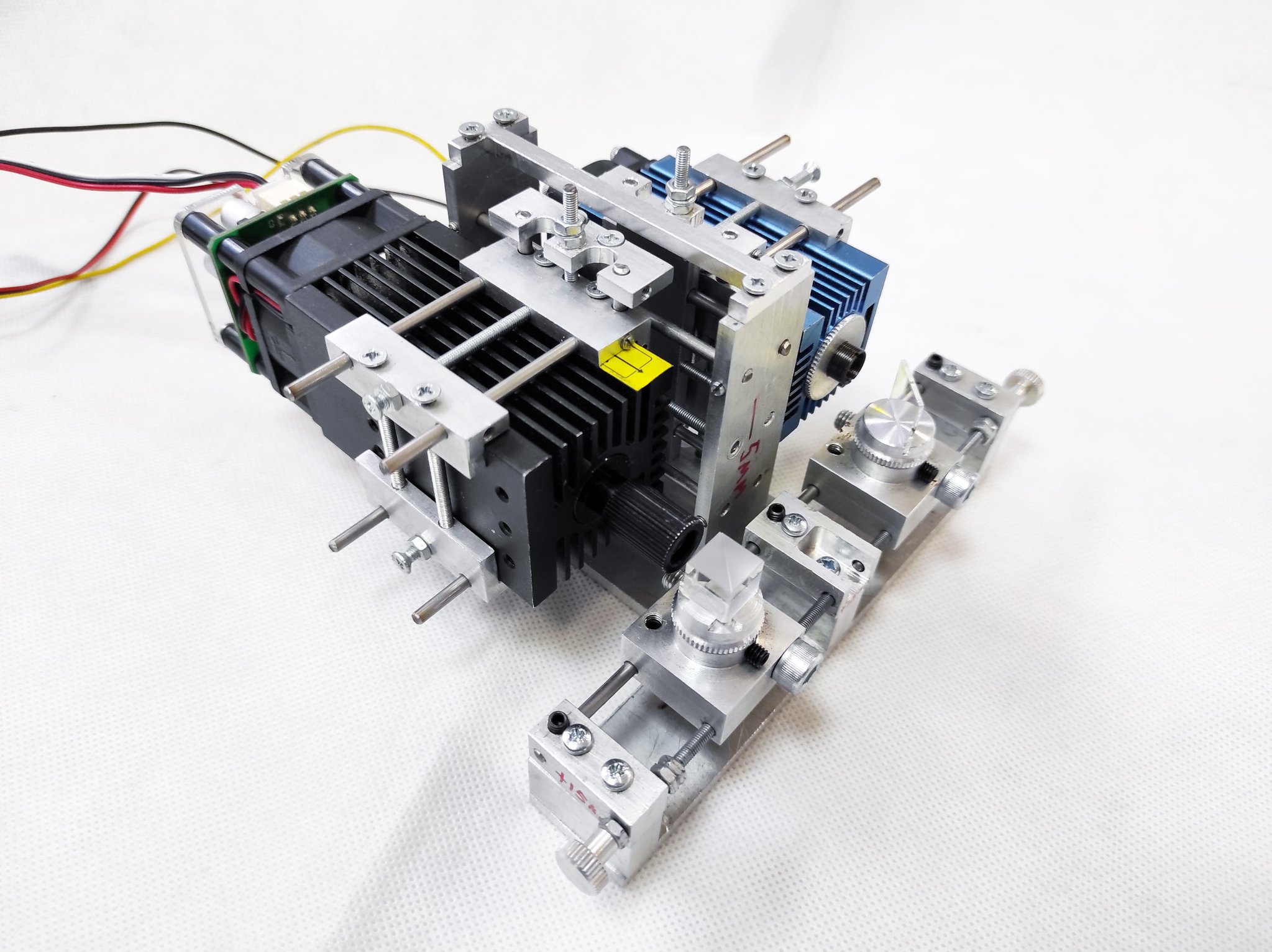
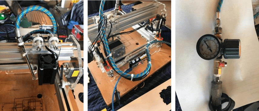
For those of you that will want to do any cutting with your laser, I suggest hooking up an air assist.
This is not my set up, but it is a good place to start.
More information can be found at T2Laser General just type in air assist in the search bar.
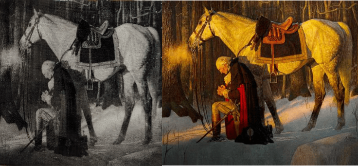
Here is a useful image for testing your greyscale (all portraits below are done with dither NOT greyscale).
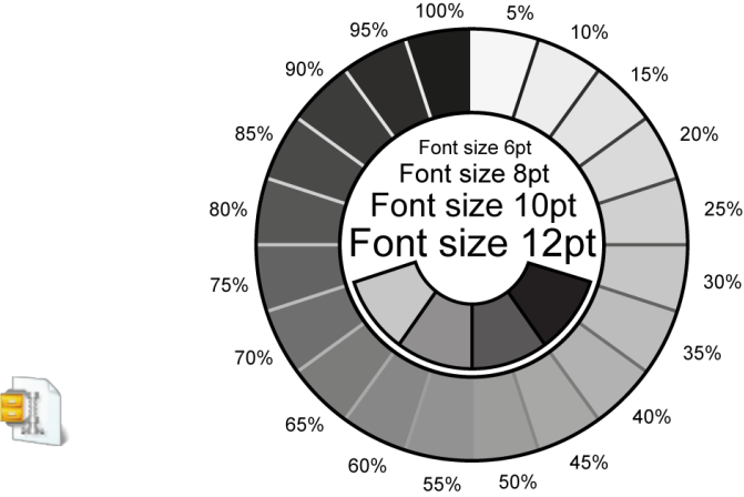
NOTE: I do not have any special picture editing programs, I simply use paint, T2Laser, and SCAL 4 pro (plotter program) for all my images.
This was the first test that I was actually able to get to work (for scale that is my pinky finger in the picture).
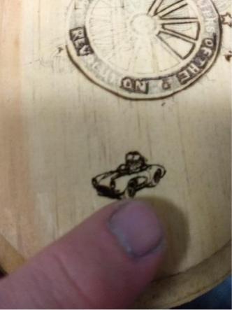
Wood:
Depending on what type of wood you are planning on using, your settings may differ, always do a test with materials you are not familiar with.
Setting were speed 1000, resolution .25, power 255 (black and white).
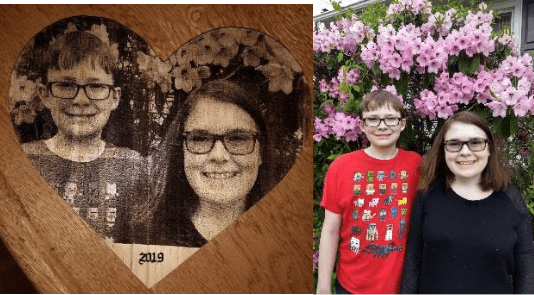
Now it was time for me to start testing and playing to see what this new “tool” (let’s admit it, it was more of a toy for me!) would do.
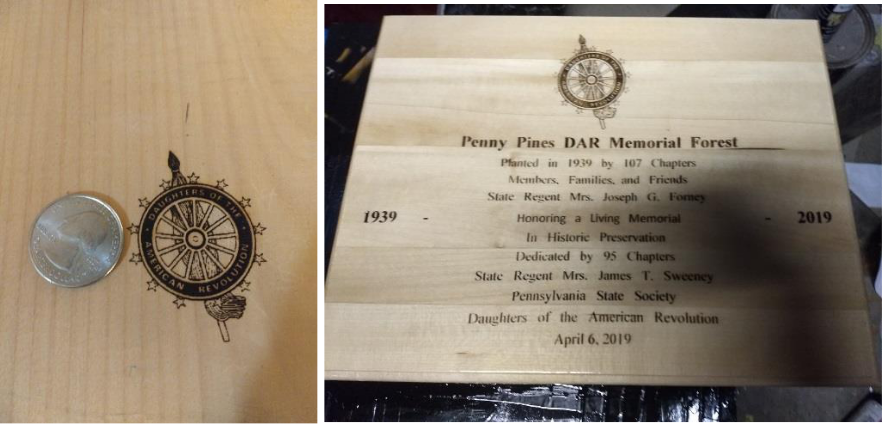
Settings speed 1000, resolution .25, power 255 (dither). On poplar board.
4” x 4” poplar board.
(Settings: speed 1200, resolution .265, Power 255 (dither)) (Original)
4” x 4” poplar board.
(Settings: speed 1200, resolution .265, Power 255(dither)) (Original)
Mirrors:
The settings for mirrors that I found works, are speed 1000, resolution .15, and power 255. (Cheap dollar general mirrors)
(Burned mirror (black and white)) (Original)
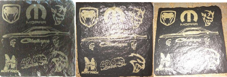
Slate:
One thing to remember depending on your design you may need to invert the color.
4” x 4” coaster from Michael’s ($3.50 for 4)
Speed 900, resolution .1, and power 255 (black and white).
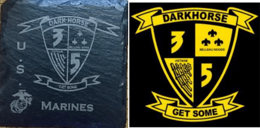
(Burned slate coaster) (Original)
One of the nice things with slate is you can actually choose between a white, and a yellowish burn, just by simply doing a second pass or lowing your speed down.
Ceramic:
Ceramic can be a bit tricky, if you use a gloss white tile, you must first paint it (I have found that flat white works best for me), some have use solvent based acrylic, I use Createx opaque white(water base) which dries into an acrylic.
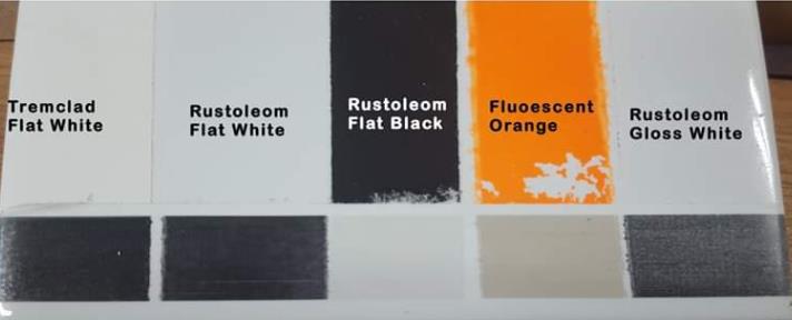
When doing Dark ceramics, you will want to remember to invert the color, depending on your design.
4” x 4” black ceramic coaster from Michaels ($3.50 for 4).
4” x 4” ceramic tile from Lowes ($.16 each).
(Burned ceramic coaster (dither)) (Original)
(Inverted color settings)
Laser Engraving and laser cutting with Endurance diode laser heads
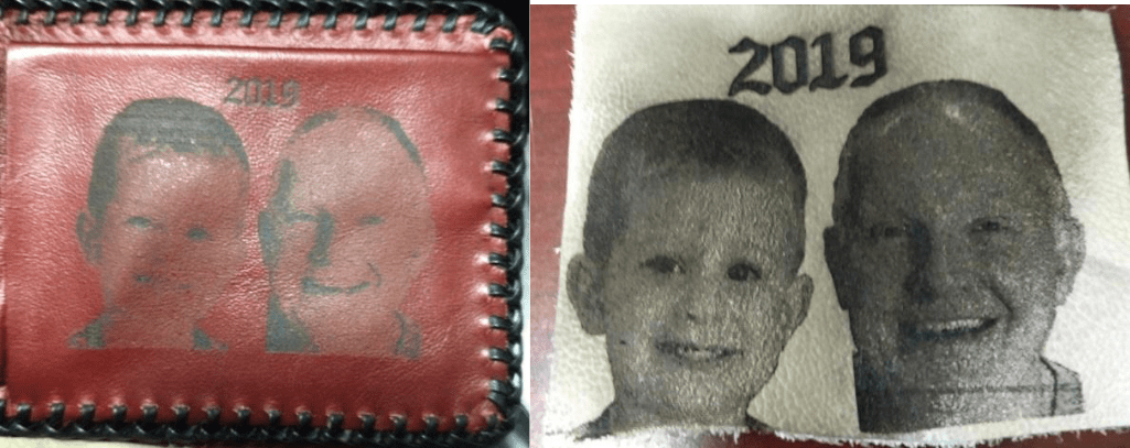
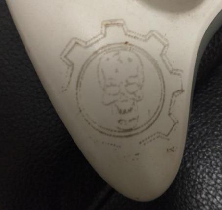
Leather:
When doing leather always do a test on similar scrap leather.
Settings speed 1200, resolution .265, Power 155 (dither).
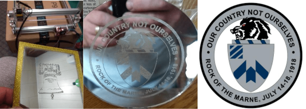
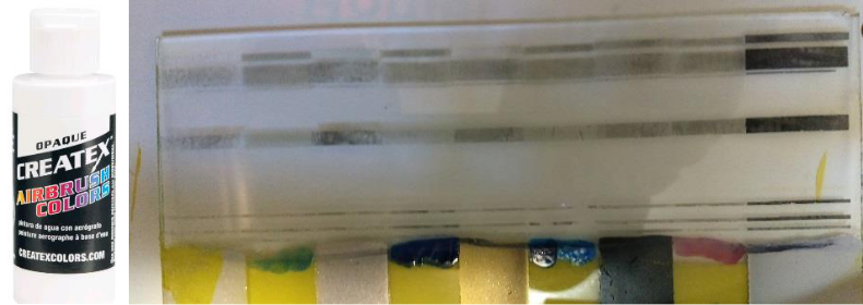
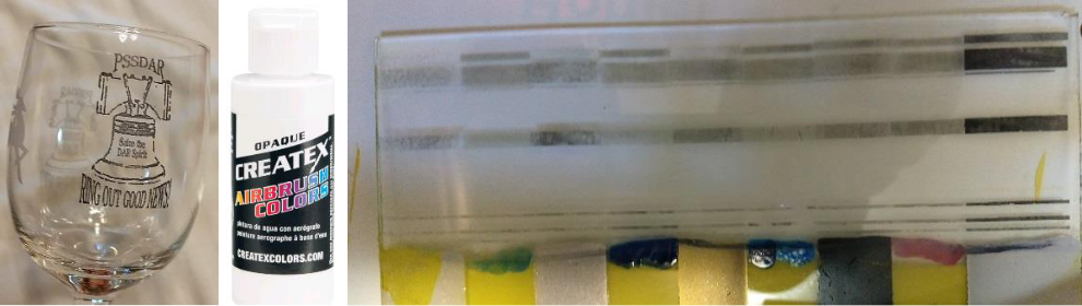
Glass:
Glass is treated much like ceramic, painted then burned.
Settings speed 1200, resolution .265, Power 255 (black and white).
Glass is out of a picture frame (free… until my wife finds out)
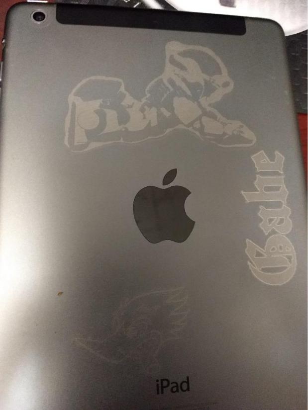
Metal backed IPad:
Much like doing slate, or dark ceramic, anything that ends up engraving at a lighter contrast should have the colors inverted.
Settings will need to be played with to find what works best for you.
Plastic:
Not recommended, but if you are going to attempt do it outside, or with a lot of air movement (it stinks), and puts of hazardous gasses.
.
So to bring my tutorial/Manual for T2Laser to a close, you can see what type of results you can accomplish with very little to no experience with this program.
Below is more information that may help, I’ve gathered it from the T2Laser page, and from other areas.
YouTube videos:
YouTube is a great source of learning videos, and walkthroughs.
https://www.youtube.com/channel/UCgtzfpP_L38kqCXdUJUm_jQ
General links that may be helpful:
T2Laser is a Benbox replacement for Grbl based laser and CNC systems.
It supports greyscale images, vector graphics and also has basic sketch features. You can add text to images, contour cut-out images or convert raster to vector and output it to the laser all in a single G-Code file.
Advanced algorithms for photo engraving and clipart/logos, as well as multi-pass vector cutting capabilities. Resolution, speed and power are user-defined so you can maximize quality while reducing the engraving time.
Manual (Shift F1) is more of a user’s guide than a manual.
T2Laser – Image to Vector
Introduction
- An image (or raster file) is made up of many dots (or pixels) that can be engraved using a back and forth scanning motion similar to an inkjet printer (e.g. jpg, bmp and png)
- A vector is a line drawing that can be cut or engraved by the machine following the path (e.g. dxf and plt)
Process
- The conversion of an image to paths is called vectorization, it can be thought of as tracing the lines in the image
Options
- T2Laser has several options for tracing
- Auto-Trace is the easiest method but you have little control over which lines get traced
- Manual Trace allows specific lines to be converted which is perfect for a simple contour cut-out
- Centerline Trace (64-bit only) is typically for line art although it can produce interesting results with any image type. Instead of tracing the edges it will attempt to determine the center of each solid area
- External Program such as Inkscape or Corel
- This method is preferred as it allows you to edit the result and prepare it for cutting or engraving. It allows more options for tracing but requires a little more skill and time
- T2Laser has several options for tracing
Example
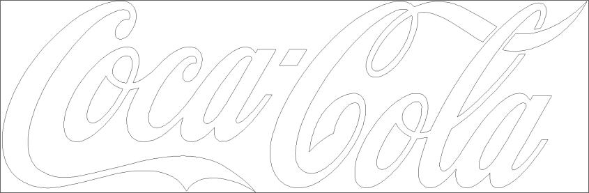
Here a simple black and white image that has been converted to vector
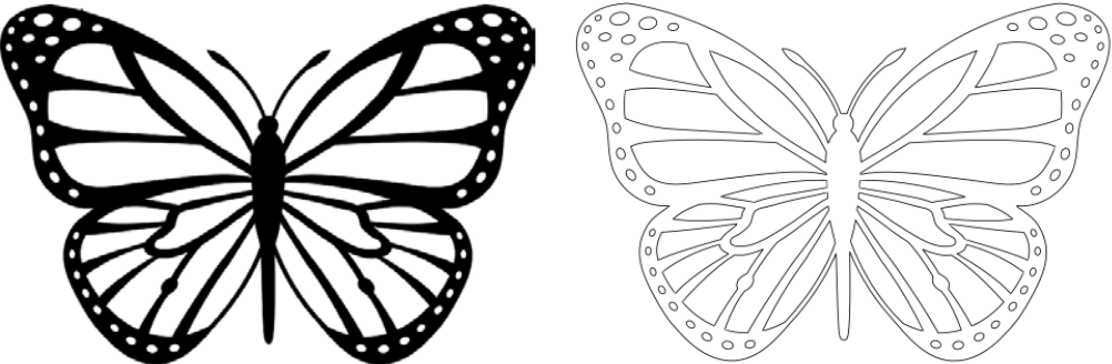 Vector files are not filled as the laser or CNC will only follow the path
- The width of the line is determined by the laser beam or cutting bit diameter
- In this example auto-trace was used, this can result in “double lines” that may not be required. Using manual trace or an external program will allow you to be selective
Auto-Trace
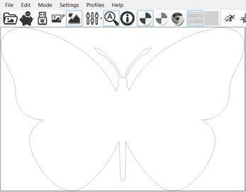
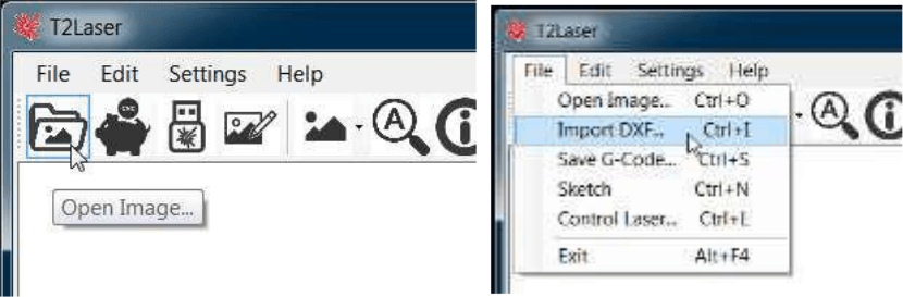
Load an image
Click the Open Image icon or select from the File Menu
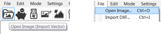
Auto-Trace
Right click the trace icon or select from the Edit Menu
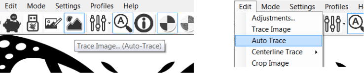
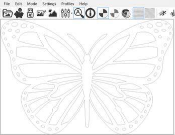
The image is traced and the result is displayed
Manual Trace
Load the image as above
Click the Trace icon or select Trace Image from the Edit Menu
Selecting the lines to trace
Click near the outline to trace it, a red line will appear showing the trace
You can right click on the image to show only the trace
If the trace is incorrect, press the delete key to remove the last line (repeat as needed)
Optionally click other areas you want to trace
Click the trace icon again or select from the menu to finish the trace
The result is displayed
Centerline Trace (64-bit systems only)
Load the image as above
Select any options
Standard, smooth and sharp determine the style of lines
Noise reduction cleans up the image (recommended)
Force lines will convert any curves to straight segments
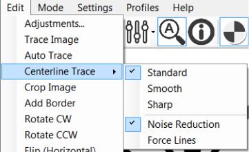
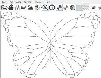
Click Centerline Trace
The result is displayed (in this case a slightly unusual effect)
External Program (Inkscape)
I will not cover using the program as there are plenty of resources for that but I will explain the benefits and how to load the result
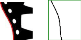
You may notice a small defect at the top of the left wing (magnified below)
As a vector this is easily corrected by deleting or smoothing the points (called nodes)
The 2nd picture below shows the trace, in the next picture the nodes are highlighted
The final picture (right) shows the result after these unwanted nodes were deleted
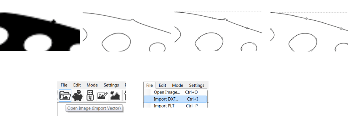
After the DXF is exported from the CAD program, load it in T2Laser
Right click the Open icon or select Import DXF from the File Menu
T2Laser has options to modify the vector file
It can be resized, flipped, rotated and even filled with a solid (raster) or hatch pattern
There are also advanced features to optimize the path for engraving, shift the origin to the lower left and use colors to determine the feed rate or power/depth of cut
T2 Laser – Automatic Hatching
Sketch and Trace
Filled
Standard Trace, only the outline is engraved
Hatch Trace, default settings (horizontal)
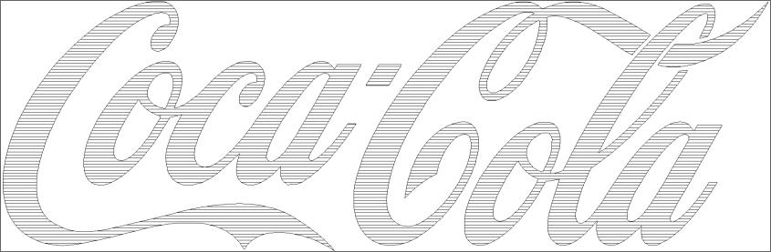
Hatch Trace, Vertical
Hatch Trace, Diagonal \
Hatch Trace, Diagonal /
Spacing Options:
Narrow
Standard
Wide
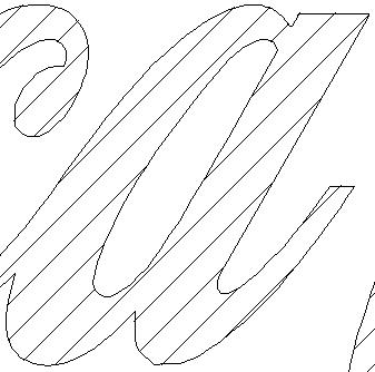
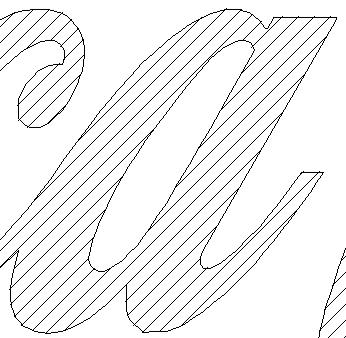
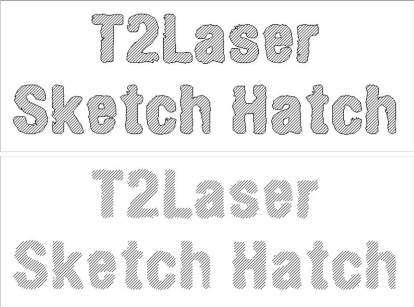
Sketch Hatch (with and without outline)
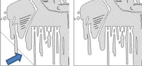
Potential Issues (unexpected lines)
These occur when the outline is not closed (open trace), and are generally easy to fix. In the below example changing the image width before tracing, from 70.3mm to 70.2mm solved it (try even numbers).
T2 Laser – DXF Conversion
Importing Vector Graphics
from Inkscape, TurboCAD & Illustrator
Note: This is not a guide to using CAD; it only covers the method to export a DXF file that can be imported to T2Laser
Inkscape 0.92
Setup your drawing
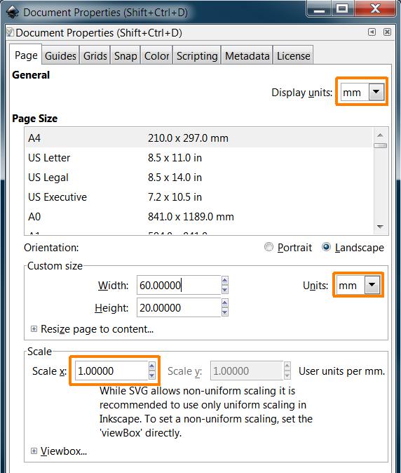
Select File / Document Properties
Set the width and height to your desired output size
In this example, I used width 60 and height 20
Make sure you select mm for the units
Display units should also be set to mm (this is used for the rulers)
The scale value should be 1.000
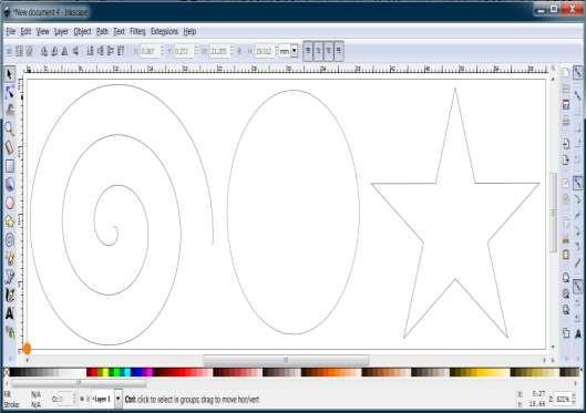
Create your drawing
Keep in mind that the 0,0 (origin) is important, it will be your start position (home)
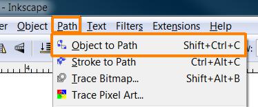
Convert text to paths
This step is only required for text objects
Select each text object separately and choose Path / Object to Path
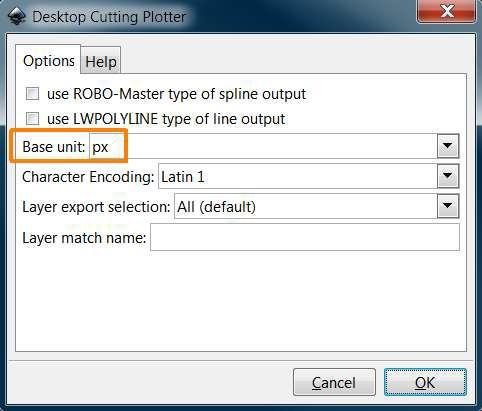
Save the DXF file
Choose File / Save As
Change the Save as type to Desktop Cutting Plotter (AutoCAD DXF R14)
Enter a name and save the file
Verify the base unit is px and do not select any other options, click OK
Load the DXF into T2Laser
Right click the Open Image tool bar icon or select File / Import DXF
The DXF is accurately imported and converted to G-Code
Example with Text i. Filled Text
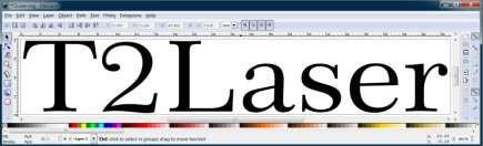
Convert the text to paths
Select the text using the arrow tool and choose Path / Object to Path
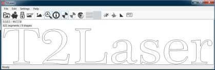
Load the DXF into T2Laser
The text is accurately imported and converted to G-Code
This example shows 9 shapes, 7 outlines and the centers of the “a” and “e”
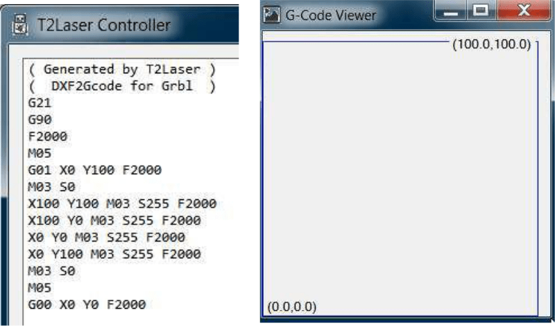
Accuracy (Dimensions)
Example using a 100mm x 100mm square (lower left corner is placed at 0,0)
Load the DXF into T2Laser
Imported shape starts at 0,0 and ends at 100,100 (exact size was maintained)
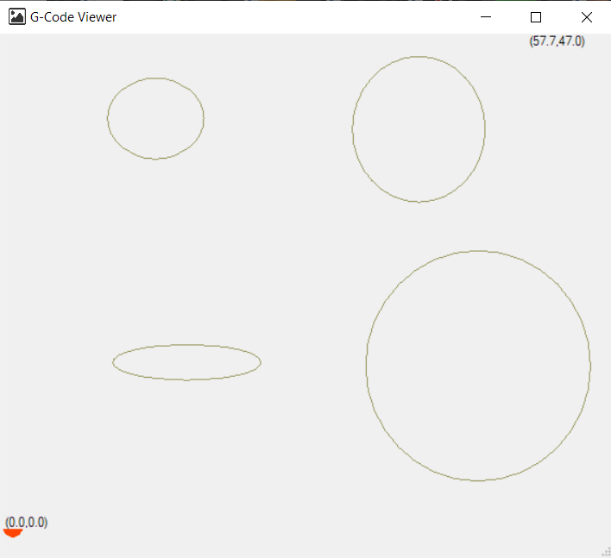
The generated G-Code is also exact, as is the simulated result in the G-Code viewer
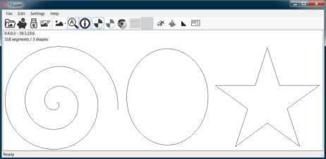
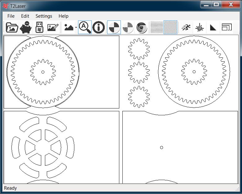
Complex Drawing
All objects are accurately imported and converted to G-Code
This example has over 4,100 segments
Use colors to define laser power levels or feed rates (customizable)
A T2Laser palette is available or you can select the colors from the Inkscape defaults
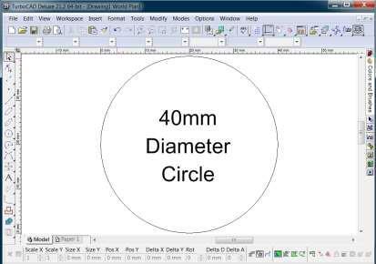
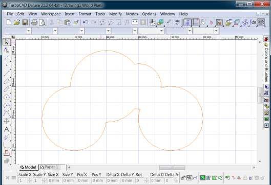
TurboCAD 21 2D/3D
Create your drawing in mm (T2Laser will automatically convert inches if you prefer)
![]()
![]()
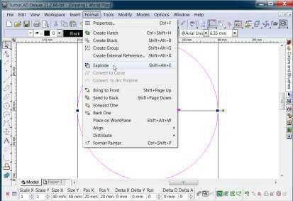
Do not use blocks – if necessary explode them before exporting i. Select objects and choose Format / Explode
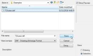
Export the DXF
Save Drawing will use the drawing origin 0,0
Save Selection uses the lowest left point as the origin 0,0
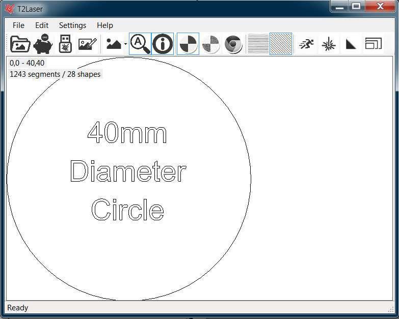
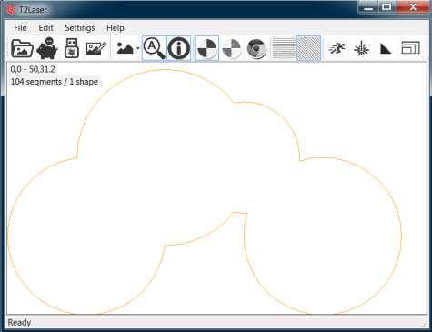
Load the DXF into T2Laser
All objects import correctly and are sized accurately
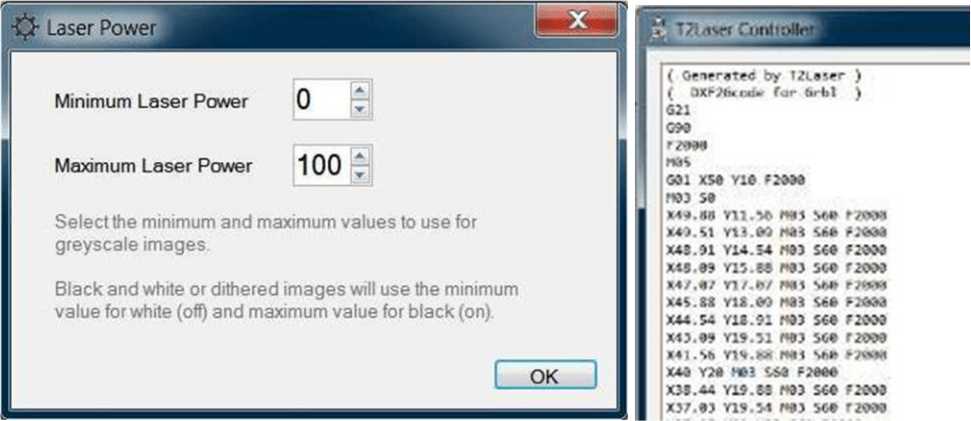
Using colors to determine laser power
Black 100%, Red 80%, Orange 60%, Blue 40%, Green 20%, Yellow 0%
Imported to T2Laser
Orange is translated to 60% of maximum power
Maximum laser power was set to 100, so orange resulted in a laser power of 60
Adobe Illustrator CS2
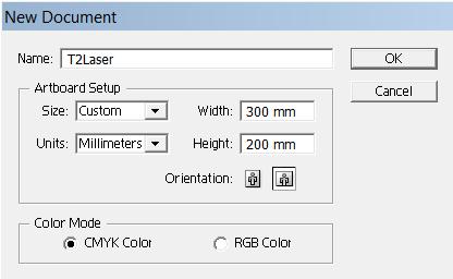
Create your document in millimeters (mm)
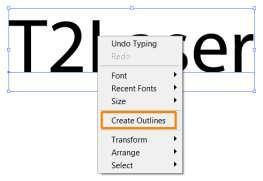
Text must have a stroke (0.25pt recommended) and will need to be converted to outlines (paths) i. Right click the text and select Create Outlines
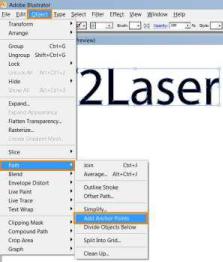
To improve the output quality it is recommended to add anchor points, repeat this as necessary to ensure the output curves match the original text (twice is usually sufficient). Select the text and click Add Anchor Points from the Object / Path menu
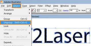
Finally, ungroup the text. Select the text and click Ungroup in the Object menu
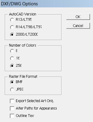
Export the DXF
Select Export from the File menu
Enter a file name and select the AutoCAD DXF file type
AutoCAD version R14 and LT2000 are acceptable
Load the DXF file into T2Laser
Sizes and positions are imported correctly
This license agreement applies to registered and evaluation versions of T2Laser software products. This software and the accompanying files are provided “as is”, no warranty is provided whatsoever, whether express, implied, or statutory, including, but not limited to, any warranty of merchantability or fitness for a particular purpose or any warranty that the contents of the item will be error-free. In no respect shall we be liability for any damages, including, but limited to, direct, indirect, special, or
consequential damages arising out of, resulting from, or any way connected to the use of this software; whether or not injury was sustained by persons or property or otherwise; and whether or not loss was sustained from, or arose out of, the results of, usage of this software. This program is protected by copyright laws and international treaties. Unauthorized distribution, reproduction, decompiling or otherwise reverse engineering of this program, or any portion of it, may result in severe civil and/or criminal penalties, and will be prosecuted to the maximum extent possible under the law.